
Lecture
When one phase is earthed in a system with an isolated neutral, the path for the current flowing to earth is provided by the capacitive conductance of each phase's elements to earth.
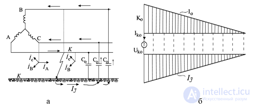
Fig.7.10. Earth fault of one phase in a system with an isolated neutral: a – schematic diagram, b – spatial distribution plot of the zero-sequence current.
The capacitances of each phase to earth, distributed along the line, are conditionally represented in Fig.7.10, a by lumped capacitive reactances. The capacitances between phases are not shown, since their effect on the earth-fault current is very small. The current circulation path is indicated in the figure by arrows.
In reality, the capacitive conductance of the line is distributed uniformly along its length, so the spatial distribution plot of the zero-sequence current, which amounts to one third of the earth-fault current, is expressed along the line by a sloping straight line (Fig. 7.8, b).
The boundary conditions for a simple earth fault are naturally the same as for a single-phase short circuit to earth. Therefore, all the expressions obtained in the section apply equally to the case of a simple earth fault.
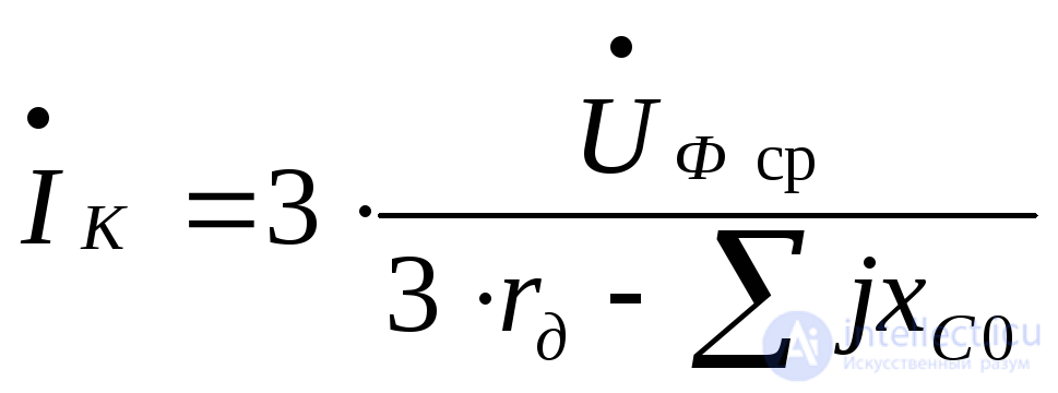
The capacitive reactances of the elements of the electrical system considerably exceed their inductive and resistive reactances, which makes it possible, when determining the current of a simple earth fault, to neglect the latter and, consequently, to assume that the magnitude of this current is practically independent of the fault location within the electrically connected network under consideration. Moreover, since this current is relatively small, when determining it the source voltage can be assumed to remain unchanged. Under these assumptions, the current at the earth-fault location through an electric arc with resistance 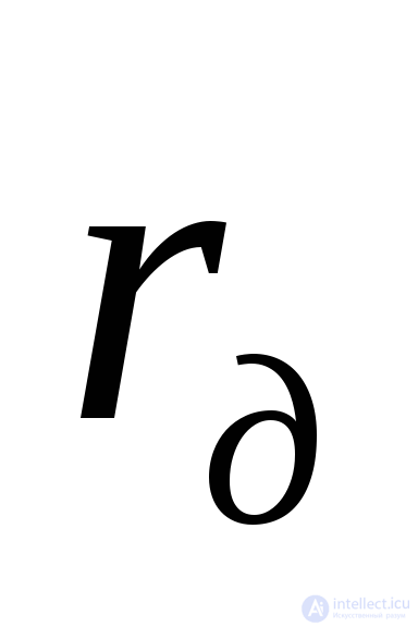 will be:
 ,
,
where  – is the resultant zero-sequence capacitive reactance of all elements electrically connected to the fault point (practically, lines and cables);
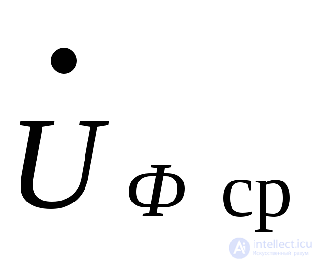 –the average phase voltage of the voltage level at which the earth fault is being considered.
The largest earth-fault current occurs in the case of a solid (metallic) fault (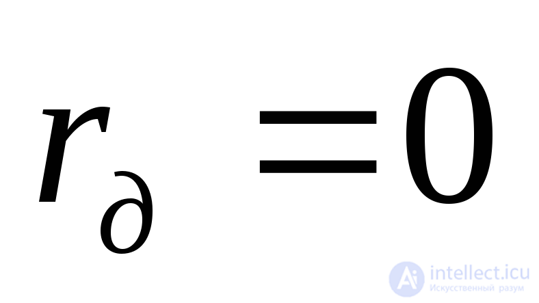 ).
).
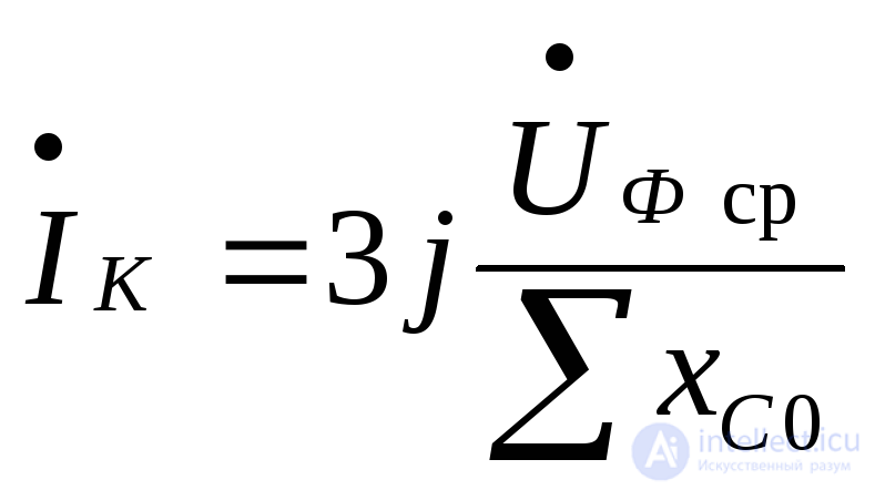 ,
,
i.e., it exceeds the capacitive current to earth under normal conditions by a factor of 3. For a rough estimate of the order of magnitude of the earth-fault current, a simplified formula can be used
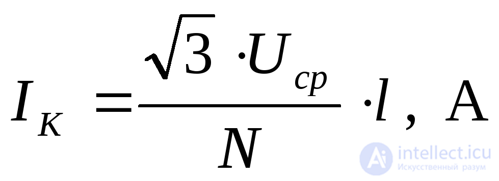 ,
,
where  – is the average rated voltage of the level at which the earth fault is being considered, kV;
 –a coefficient taken as 350 for overhead lines and 10 for cable lines;
 –the total length of overhead or cable lines electrically connected to the earth-fault point, km.
For the symmetrical components of the voltages beyond the arc resistance, under the adopted assumptions, we have
 , (7.36)
 , (7.37)
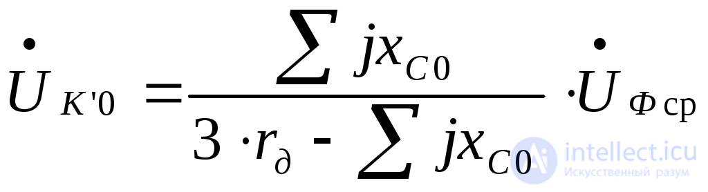 . (7.38)
Similarly to the complex equivalent circuit for a single-phase short circuit to earth, an equivalent circuit of the same kind can be constructed for a simple earth fault. An example of such a complex circuit is shown in Fig.7.11.
From the circuit shown, it directly follows that in order to limit the current of a simple fault, it is advisable to earth the transformer neutral through an inductive coil (shown by the dashed line). The inductance of such a coil can be selected so as to ensure resonance between the inductance and the capacitance, which leads to 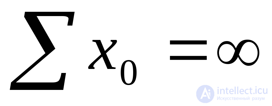 , i.e. to complete compensation of the simple earth-fault current. This condition is satisfied when
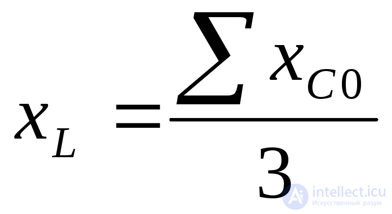 .
.
Operating experience with power supply systems shows that in earth faults through an arc and small values of  the arc extinguishes practically without repeated re-ignitions and the accompanying overvoltage surges. As the current
 increases, repeated re-ignitions of the arc and overvoltages are observed, which increases the probability of a single-phase earth fault developing into a phase-to-phase short circuit. Therefore, in accordance with the electrical installation design rules, in networks with an isolated neutral, at certain values of
 compensation of the capacitive earth-fault currents must be performed by connecting an inductive reactance
 (an arc-suppression device) into the neutral.
It has been established experimentally that, to ensure self-extinction of an arc arising from a simple fault, the earth current must not exceed
at 6 kV – 30 A,
at 10 kV – 20 A,
at 35 kV – 10 A.
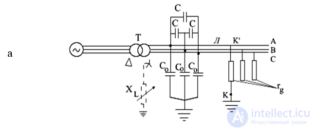
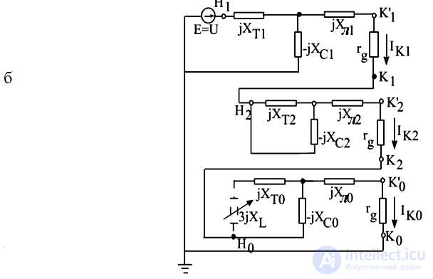
Fig.7.11. Simple earth fault through an arc:
a – original circuit; b – complex equivalent circuit

Comments