
Lecture
The methods of circuit analysis considered so far – direct application of Kirchhoff's laws, the loop-current method, and the node-voltage method – make it possible, in principle, to analyze any circuit. However, using them without the topological matrices introduced earlier is practical only for relatively simple circuits. The use of matrix methods of analysis makes it possible to formalize the process of writing the equations of the electromagnetic balance of a circuit, and also to organize data entry into a computer, which is especially important when analyzing complex branched circuits.
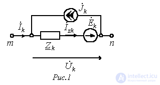
Turning to matrix methods of circuit analysis, let us write Ohm's law in matrix form.
Let us consider the circuit shown in Fig. 1, where  is a current source. In accordance with Ohm's law for a branch with an EMF, considered earlier, we can write for this circuit:

However, for the further derivation it will be more convenient to represent the current  as the sum of the currents of the k-th branch and of the current source, i.e.:

Substituting (2) into (1), we obtain:

Formula (3) is the analytical expression of Ohm's law for a branch containing both an EMF source and a current source (a generalized branch).
Let us write relation (3) for all n branches of the circuit in the form of a matrix equality
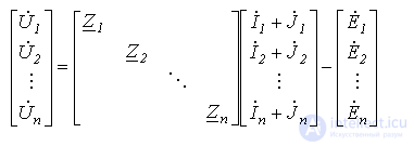
or
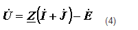
where Z – is the diagonal square (n x n) matrix of branch resistances, all of whose elements (we do not take mutual inductance into account), except for the elements on the main diagonal, are equal to zero.
Relation (4) is the matrix form of Ohm's law.
If both sides of equality (4) are multiplied on the left by the loop matrix B and Kirchhoff's second law is taken into account, according to which
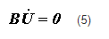
then

that is, we have obtained a new matrix-form statement of Kirchhoff's second law.
Loop-Current Method in Matrix Form
In accordance with the previously introduced concept of the fundamental-loop matrix B, written for the fundamental loops, let us take as the independent variables the currents of the link (connecting) branches, which will be equal to the desired loop currents.
The loop-current equations are obtained on the basis of Kirchhoff's second law; their number equals the number of independent equations that can be written for the loops, i.e., the number of link branches c=n-m+1. Let us write expression (6) as follows:
 (7)
(7)
In accordance with the loop-current method, the currents of all branches can be expressed as linear combinations of the loop currents, or in the case under consideration, of the currents of the link branches. If the elements of the j–th column of matrix B are multiplied in the appropriate way by the loop currents, then the sum of these products gives the current of the j–th branch expressed in terms of the loop currents (of the link-branch currents). This can be written as the matrix relation
| . |
 , , |
(8) |
where  - is the column matrix of loop currents;
  - is the transposed loop matrix.
Taking (8) into account, relation (7) can be written as:
 |
(9) |
The resulting equation represents the loop equations in matrix form. If we denote
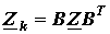 , , |
(10) |
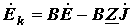 . . |
(11) |
then we obtain the matrix form of the equations written by the loop-current method:
 , , |
(12) |
where  - is the matrix of loop resistances;
  - is the matrix of loop EMFs.
In expanded form, (12) can be written as:
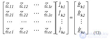
that is, we have obtained the result already known from the loop-current method.
Let us consider an example of writing the loop equations.
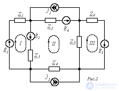
Let us consider the circuit shown in Fig. 2. This circuit has four nodes (m=4) and six generalized branches (n=6). The number of independent loops, equal to the number of link branches,
c=n-m+1=6-4+1=3.
The graph of the circuit with the chosen tree (branches 1, 2, 3) is shown in Fig. 3.
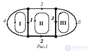
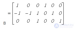
Let us write the loop matrix, which will be the fundamental-loop matrix, since each link branch belongs to only one loop. Taking the directions of the link branches as the directions for traversing the loops, we obtain:
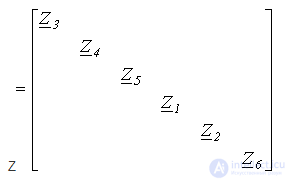
The diagonal matrix of branch resistances
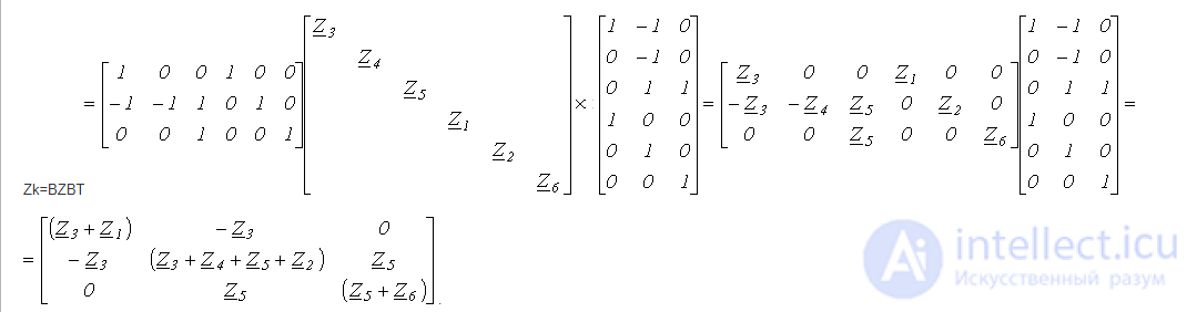
The matrix of loop resistances
The matrices of EMFs and source currents
 |
 |
 |
 |
Then the matrix of loop EMFs
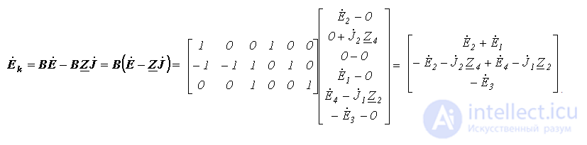
The matrix of loop currents
 |
 . . |
Thus, we finally obtain:
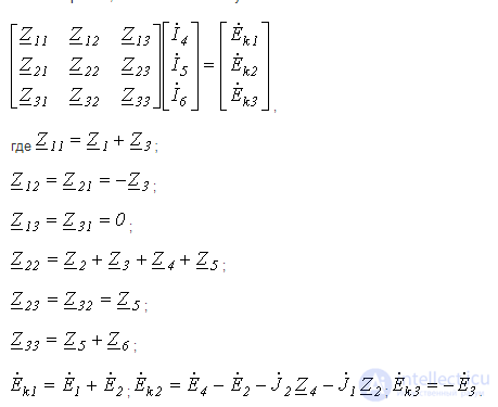 .
.
Analysis of the results shows that the three equations obtained are identical to those that can be written directly from the circuit by the known rules for writing equations by the loop-current method.
Node-Voltage Method in Matrix Form
On the basis of relation (4) obtained above, which, as noted, is the matrix form of Ohm's law, let us write the matrix expression:
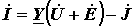 , , |
(14) |
where 
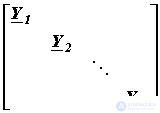 - is the diagonal matrix of branch conductances, all of whose terms, except for the elements on the main diagonal, are equal to zero.
The matrices Z and Y are mutual inverses.
Multiplying both sides of equality (14) by the node (incidence) matrix A and taking into account Kirchhoff's first law, according to which
 , , |
(15) |
we obtain:
 .. .. |
(16) |
Let us rewrite expression (16) as:
 . . |
(17) |
Taking the potential of the node for which there is no row in matrix A, to be zero, let us determine the voltages across the branch terminals:
 . . |
(18) |
Then we obtain a matrix equation of the form:
 . . |
(19) |
This equation represents the node equations in matrix form. If we denote
 |
(20) |
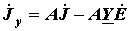 , , |
(21) |
then we obtain the matrix form of the equations written by the node-voltage method:
 |
(22) |
where  - is the matrix of node conductances;
  - is the matrix of node currents.
In expanded form, relation (22) can be written as:
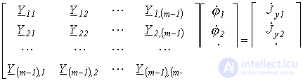 |
(23) |
that is, we have obtained the result already known from the node-voltage method.
Let us consider the writing of the node equations using the circuit of Fig. 4 as an example.
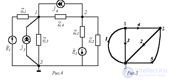
This circuit has 3 nodes (m=3) and 5 branches (n=5). The graph of the circuit with the chosen orientation of the branches is shown in Fig. 5.
The node (incidence) matrix (let us take  )
)
A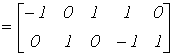
The diagonal matrix of branch conductances:
Y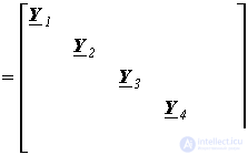
where  .
.
The matrix of node conductances
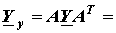
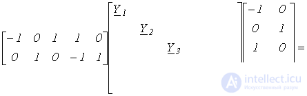
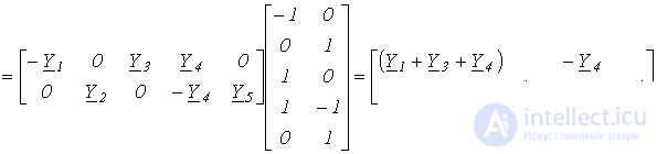 .
.
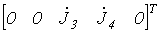
The matrices of source currents and EMFs
 |
 |
 |
 |
Consequently, the matrix of node currents has the form:
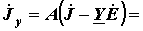
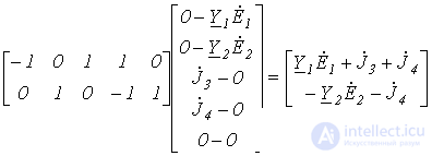
Thus, we finally obtain:
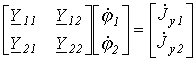 ,
,
where  ;
;  ;
;  ;
;  ;
; 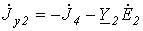 .
.
Analysis of the results shows that the equations obtained are identical to those that can be written directly from the circuit by the known rules for writing equations by the node-voltage method.
Answer:

Answer:


Comments