
Lecture
When applying the method of symmetrical components to the analysis of any unbalanced condition, one of the primary tasks is to build the equivalent circuits, in the general case, for all three sequences: positive, negative, and zero. In the analytical solution of the problem, these circuits are used to find the resultant impedances of the individual sequences of the system under consideration relative to the point where the asymmetry occurred. In addition, the resultant EMF relative to the same point is found from the positive-sequence equivalent circuit. The parameters of the circuit elements are expressed in named units or in per-unit values, referred, respectively, to the voltage level selected as the base level or to the selected base conditions.
The positive-sequence circuit is identical to the circuit that is built for the analysis of any symmetrical three-phase condition.
Since the paths of circulation of negative-sequence currents are the same as those of positive-sequence currents, the negative-sequence circuit is structurally analogous to the positive-sequence circuit. The difference between them is that in the negative-sequence circuit, the EMFs of all generating branches are conventionally taken as equal to zero.
The starting point of the positive- or negative-sequence circuit is chosen as the point at which the free ends of all generating and load branches are joined. This is the zero-potential point of the circuit for the corresponding sequence. The end point of the positive- or negative-sequence circuit is taken as the point where the asymmetry under consideration occurred. In the case of series asymmetry, each of the circuits has two end points: these are the two points between which the given series asymmetry is located. Voltages of the corresponding sequences, arising at the location of the asymmetry, are applied to the end point or between the end points of the circuits of the individual sequences.
The zero-sequence current is, in essence, a single-phase current, split between the three phases and returning through the ground and other circuits parallel to it, since the path of the zero-sequence currents differs from the path of the positive- and negative-sequence currents. The zero-sequence circuit is largely determined by the connection of the windings of transformers and autotransformers.

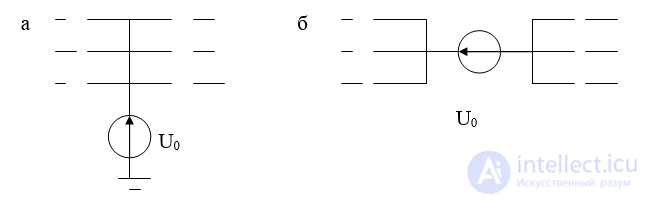


Fig. 6.6. Zero-sequence voltage: a – for transverse, b – for series asymmetry
Building the zero-sequence circuit should, as a rule, begin from the point where the asymmetry occurred. Depending on the type of asymmetry, a zero-sequence voltage is applied to this point, either relative to ground (Fig. 6.5.a), or in series, inserted into the phase conductors (Fig. 6.5.b). When the zero-sequence voltage is applied relative to ground, then, in the absence of capacitive coupling, at least one grounded neutral is required within the same electrically connected circuit where this voltage is applied, in order for zero-sequence currents to circulate.
In the case of series asymmetry, that is, when the zero-sequence voltage is introduced in series into the phase conductors, circulation of zero-sequence currents is possible even in the absence of grounded neutrals, provided there is a closed loop through bypass paths of the same electrically connected circuit. In this case, an induced current circulates in the ground, following the route of the line.
The resistance through which the neutral of a circuit element is grounded must be introduced into the zero-sequence network at triple its value.
Fig. 6.6 shows an example of constructing the zero-sequence network for the case of a transverse asymmetry. The arrows indicate the paths of circulation of the zero-sequence currents.
If it is assumed that at the same point the zero-sequence voltage is applied at a break in the conductors (a longitudinal asymmetry), then in this case the equivalent circuit remains the same, but its resulting impedance will be quite different.
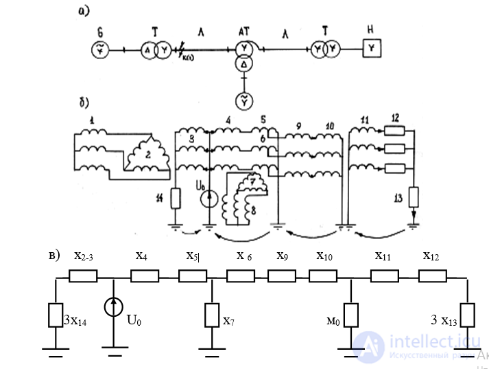
Fig. 6.7. Example of a zero-sequence network: a – original circuit, b – circuit in three-phase form, c – zero-sequence equivalent circuit
+The resistance through which the neutral of a transformer, generator, motor, or load is grounded must be introduced into the zero-sequence network at triple its value. This is because the zero-sequence network is constructed for a single phase, while the sum of the zero-sequence currents of all three phases flows through the said resistance.
equivalent circuits

Comments