
Lecture
The most accurate description of transient processes in both synchronous and induction motors is given by the system of Park-Gorev equations. However, in doing so some factors must be taken into account that are not significant for transient processes in generators.
Generator regimes are always limited to small slips, whereas the slip of synchronous (and induction) motors can vary from zero to unity. At large slips, the current-displacement effect in the rotor damper circuits manifests itself significantly. This effect can be accounted for by using several damper circuits on each axis, which leads to an increase in the number of Park-Gorev equations, as well as in the number of terms in the flux-linkage equations. The current-displacement effect can be accounted for approximately by keeping one damper circuit per axis of the machine, if dependences of 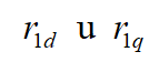 on slip are introduced. These dependences are similar to the dependences
  , characteristic of induction motors.
The system of equations (3.2) includes the values of the synchronous reactances 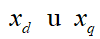 , of the field winding
  and of the damper windings
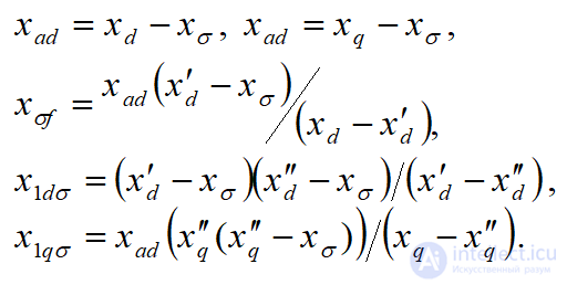
 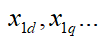 . These reactances consist of the mutual-inductance reactance along the corresponding axis
  and the leakage reactance
 :
:

The synchronous  , transient
  and subtransient
  reactances are given in the motor nameplate data. The stator leakage reactances of salient-pole motors
The system of Park-Gorev equations for synchronous motors includes the following quantities:
The active stator resistance is determined by the expression
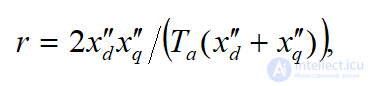
where Ta – the decay time constant of the aperiodic stator currents.
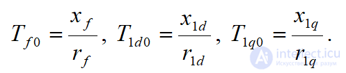
The active resistance of any rotor circuit, with the other circuits open, is determined through the corresponding time constant, related to them by the relations
The transient process in synchronous motors proceeds in the same way as in synchronous generators. However, at the initial instant of the transient process, motors have different values of the subtransient EMF. For an overexcited synchronous motor, the subtransient EMF is higher than the applied voltage. In this case, a sharp voltage drop leads to an increase in the reactive current generated by the motor. In the case of underexcitation of a synchronous motor, its EMF is lower than the applied voltage and reactive current is drawn from the network; when the EMF and voltage are equal, there is no reactive current at the start of the transient process.
Induction motors, at the initial instant of the transient process, can be regarded as overexcited synchronous motors, since in normal operation they run with small slip (2...5%). For induction motors, the system of Park-Gorev equations is used in cases where it is necessary to account for electromagnetic transient processes.
The full symmetry of the induction machine and the absence of excitation make it possible to simplify the equations and represent them in a more convenient coordinate system. In this case 
+However, the significant dependence of the rotor parameters on the frequency of the currents in the motor, whose model contains one rotor circuit per axis with constant parameters  , leads to significant errors in calculating transient processes at large slip variations.
For a more accurate description of electromagnetic transient processes in induction machines, it is necessary to represent the rotor by several circuits in each axis.
The mechanical part of the drive can be reduced to a single generalized rigid mechanical link with an equivalent mass having a moment of inertia J, acted upon by the motor's driving torque M and the total resistance torque (static torque) Mc, referred to the motor shaft, which includes all mechanical losses in the system, including the mechanical losses in the motor itself (Fig. 7.1). Then the equation of motion of the electric drive takes the form
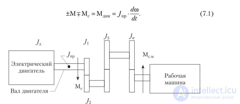
Fig. 7.1. Kinematic diagram of the electric drive
The moment of inertia can be expressed as

where r and D — are the radius and diameter of the rotor, m; G — weight, N; g — acceleration of gravity, 9.81 m/s2.
The quantity entering equation (7.2)

is called the flywheel moment. For electric motors, numerical values of the flywheel moment are given in electrical equipment catalogs.
From equation (7.1) it follows that when:
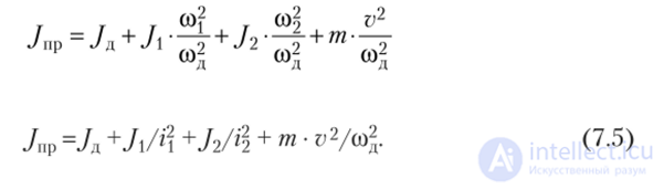
When determining the equivalent (reduced) moment of inertia Jred (Fig. 7.2), one must proceed from the law of conservation of energy, i.e., the store of kinetic energy must remain constant.

whereJ1JM2 — moments of inertia of individual drive units; m — mass of elements moving translationally at velocity v.
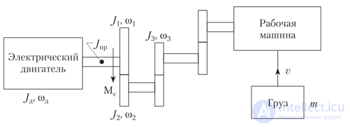
Fig. 7.2. Diagram for determining the equivalent moment of inertia
Solving equation (7.4) for J, we obtain
or
Based on this equation, one can determine:
Calculation of the duration of transient processes of an electric drive.
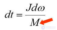
Based on the basic equation of motion of an electric drive with constant moment of inertia, we can write
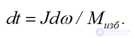
To determine the duration of the mechanical transient process, it is sufficient to integrate this expression.
Because of the difficulty of representing an analytical dependence of the excess torque on rotational speed
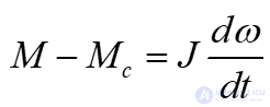
and its subsequent integration, an approximate solution of the equation using the finite-difference method is used instead.
The essence of the finite-difference method consists in replacing the differentials of the variables dt and dω with their finite small increments Δt and Δω on each i-th section of acceleration or braking of the electric drive.
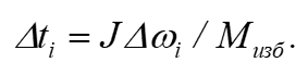
For a given small increment Δωi on the i-th section, the excess torque of this section can be considered constant and equal to its average value.
Thus, the total duration of the transient process of the electric drive will equal
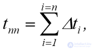
where n is the number of sections into which the speed interval is divided.
Taking into account the previous expression, this relation can be represented as
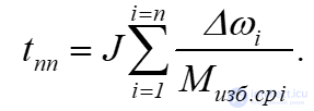
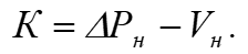
The total power losses in an electric motor ΔP consist of a constant component K and a variable component V. Constant losses refer to power losses that do not depend on the motor load. These include losses in the core steel, mechanical losses from bearing friction, and ventilation losses. The constant power losses equal
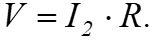
Variable losses refer to the losses dissipated in the motor windings due to the currents determined by the mechanical load of the electric drive. The variable power losses in DC motors:
In three-phase induction motors

where V1 and V2 are the power losses in the stator and rotor winding circuits, respectively.
Using the Γ-shaped equivalent circuit of the motor
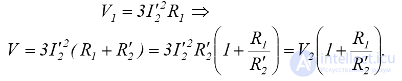
The variable power losses dissipated in the rotor of an induction motor can be determined through mechanical variables and parameters
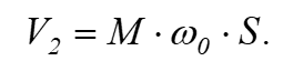
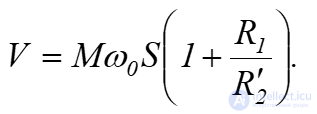
Then the total variable losses will equal
Determining the electrical energy losses in transient processes is highly important for motors in which dynamic operation is the primary mode. These include electric drives of rolling mills, hoisting cranes, planing machines, elevators, etc.
The starting energy losses of an induction motor are almost entirely determined by the electrical energy losses in the windings, which are directly proportional to the square of the current
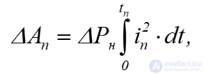
where ΔPn is the rated electrical power loss of the motor, W; i is the current ratio of the motor relative to its rated value.
For a squirrel-cage induction motor, the equivalent current value over the starting period is approximately 0.9 of its starting value at ω=0
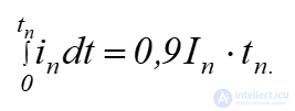
Taking this into account
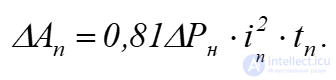
The rated electrical power losses of the motor equal
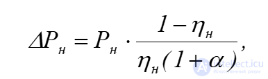
where α is a coefficient equal to the ratio of the constant power losses to the rated variable losses,
α=0.5…0.7 for general-purpose induction motors;
α=0.4…1 for crane-duty induction motors.
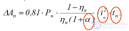
Taking into account the previous relation, the design formula for determining the starting energy losses has the form

Through mechanical variables and parameters, the power loss at motor starting without load (Mc=0) is determined by the formula

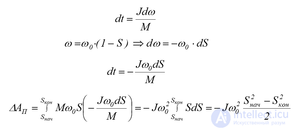
At motor starting and dynamic braking, Sinit=1, Sfin=0, then
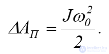
At plugging (reverse-current braking), Sinit=2, Sfin=1, and the energy loss is
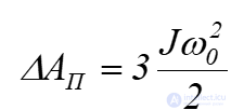
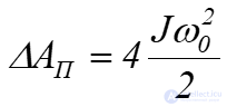
At reversal, Sinit=2, Sfin=0, and the energy loss is
Energy losses, and correspondingly the heating of motors in transient modes, can be reduced in the following ways:
When considering the dynamics of various electric drives, the problem arises of evaluating their stable operation under external mechanical disturbances that give rise to an excess torque in the drive system (this can occur, for example, when the load or supply conditions change).
Static stability of an electric drive is considered when the duration of the excess load torque exceeds the duration of the resulting transient process. Dynamic stability is considered for a short-term occurrence of excess torque. When an external disturbance arises in the electric drive system, the equation of motion can be written as
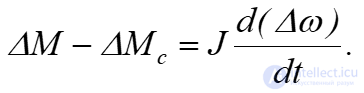
Taking into account
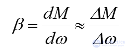
we obtain
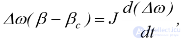
where β, βc are the stiffnesses of the mechanical characteristics of the motor and the driven machine.
Separating variables, we write the differential equation
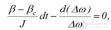
solving which, we obtain
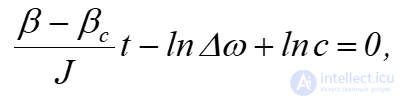
where c is the constant of integration.
From the initial conditions at t=0, Δω=Δωinit. Then, based on the last relation, c=Δωinit.
Therefore
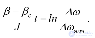
Finally
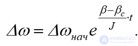
From the previous equation it follows that, to ensure static stability, it is necessary that as t→∞, Δω→0, which is possible under the condition

This relation serves as the stability criterion of the electric drive, according to which the drive operation is stable if the stiffness of the mechanical characteristic of the static load is greater than the stiffness of the mechanical characteristic of the motor at their intersection point.
During operation of the drive, the static overload resistance torque Msp, acting from the load side, may exceed the maximum permissible motor torque M1 for a short interval of time, whose total duration is less than the duration of the resulting electromechanical transient process.
Under dynamic stability, the operability of the drive is maintained due to the additional action of the kinetic energy of the moving masses of the electric drive, even under formal static instability
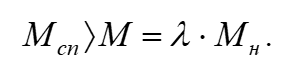
The working section of the mechanical characteristic is approximated by a straight line. In this case, under shock loading, the increase in motor torque follows an exponential law

where M0 – is the motor torque during operation prior to overload, N·m;
Tm - electromechanical time constant of the electric drive, s.
For an electric drive with an induction motor

where Sn - slip of the induction motor at rated load torque.
The motor torque reaches its maximum value after a certain permissible overload time has elapsed.
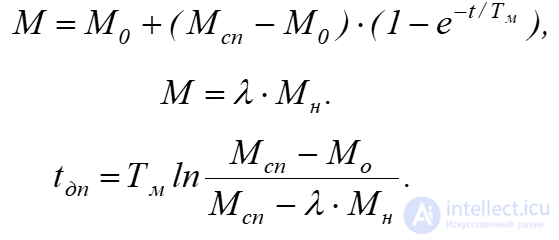
If the actual duration of the shock load application
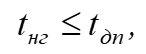 then the operation of the electric drive is dynamically stable.
If, however,
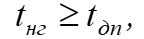 then the operability of the drive is compromised.

Comments