
Lecture
The previous lectures were devoted to the analysis of electric circuits under sinusoidal currents and voltages. In practice, EMFs and currents are, to a greater or lesser extent, non-sinusoidal. This is because real generators do not, strictly speaking, provide a sinusoidal voltage waveform, while, on the other hand, the presence of nonlinear elements in a circuit causes distortion of the current waveform even when the source EMFs are sinusoidal.
In practice, the non-sinusoidal nature of voltages and currents must be approached in two ways:
In the general case, the character of variation of a quantity may be periodic, almost periodic, or non-periodic. This section will deal only with circuits having periodic variables.
Periodic non-sinusoidal quantities are variables that change with time according to a periodic non-sinusoidal law. The causes of non-sinusoidal voltages and currents may be the non-sinusoidal nature of the supply source, or (and) the presence in the circuit of at least one nonlinear element. In addition, elements with periodically varying parameters can also underlie the appearance of non-sinusoidal currents.
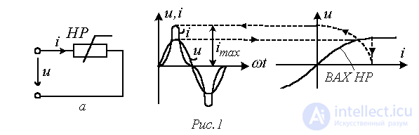
As an example, Fig. 1,a shows a circuit with a nonlinear resistor (NR), whose nonlinear current-voltage characteristic (CVC) causes the current i in the circuit to be non-sinusoidal even though the voltage u at its input is sinusoidal (see Fig. 1,b).
Characteristics of non-sinusoidal quantities
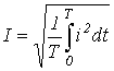
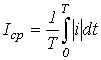
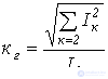
The following quantities and coefficients are used to characterize non-sinusoidal periodic variables (given here for the example of a periodic current):
 .
. .
. .
. .
. .
. .
. .
. .
.Expansion of periodic non-sinusoidal
curves in a Fourier series
It is known from mathematics that any periodic function  , where T – is the period, satisfying the Dirichlet conditions, can be expanded into a trigonometric series. It may be noted that the functions considered in electrical engineering satisfy these conditions, so there is no need to check for their fulfillment.
When expanded in a Fourier series, the function is represented as follows:
 . . |
(1) |
Here 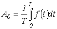 - the DC component, or zero harmonic;
  - the first (fundamental) harmonic, varying at the angular frequency
  , where T – is the period of the non-sinusoidal periodic function.
In expression (1)  , where the coefficients
  and
and  are determined from the formulas
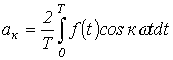 ;
;
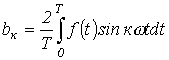 .
.
Properties of periodic curves possessing symmetry
The Fourier series coefficients for standard functions can be taken from reference literature or, in the general case, calculated from the formulas given above. However, for curves that possess symmetry, the task is substantially simplified, since entire spectra of harmonics drop out of their expansion. Knowledge of the properties of such curves makes it possible to save considerable time and resources in calculations.
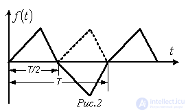
This type includes curves satisfying the equality  (see the example in Fig. 2). Their expansion contains no DC component and no even harmonics, i.e.,
  .
.
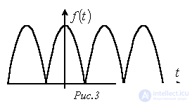
This type includes curves for which the equality  holds (see the example in Fig. 3). Their expansion contains no sine components, i.e.,
  .
.
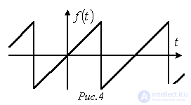
This type includes curves satisfying the equality  (see the example in Fig. 4). The expansion of such curves contains no DC component and no cosine components, i.e.,
  .
.
RMS value of a periodic non-sinusoidal variable
As shown above, the RMS (root-mean-square) value is the value defined as the square root of the mean, over one period, of the squared quantity:
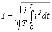 .
.
If an analytical expression for the function i(t) is available and the integral of its square can be taken, the RMS value of i(t) is determined exactly. In the general case, however, in practice the RMS value of the variable is determined from information about the RMS values of a finite set of harmonics.
Let 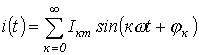 . Then
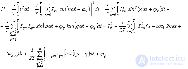
Obviously, each of the integrals of the trigonometric functions in the last expression is equal to zero. Thus,
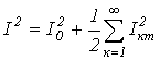
or
 .
.
Analogous expressions hold for EMF, voltage, etc.
Power in circuits with periodic non-sinusoidal current
Let 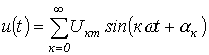 and
and 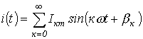 .
.
Then for the active power we can write
 .
.
As shown when deriving the relation for the RMS value of a non-sinusoidal variable, the average value over a period of the product of sinusoidal functions of different frequencies is equal to zero. Consequently,
 ,
,
where  .
.
Thus, the active power of a non-sinusoidal current equals the sum of the active powers of the individual harmonics:
 .
.
Similarly, for the reactive power we can write
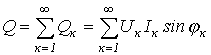 .
.
Apparent power
 ,
,
where T – is the distortion power, determined by the products of the RMS values of the different-order harmonics of current and voltage.
Method for calculating linear circuits under periodic non-sinusoidal currents
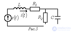
The possibility of expanding periodic non-sinusoidal functions in a Fourier series makes it possible to reduce the calculation of a linear circuit driven by non-sinusoidal source EMFs (or currents) to the calculation of circuits with DC and sinusoidal currents separately for each harmonic. The instantaneous values of the sought currents and voltages are determined on the basis of the superposition principle, by summing the harmonic components of voltages and currents found in the calculation. In accordance with the above, the circuit in Fig. 5, driven by an EMF
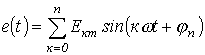
(in the calculation the spectrum of the harmonics considered is limited) is represented, for calculation purposes, as the sum of the circuits in Fig. 6.
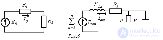
Here  .
.
Then, for example, for the current in the branch containing the EMF source, we have
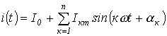 ,
,
where each k-th harmonic of the current is calculated by the symbolic method using its own k-th equivalent circuit. Here (skin effect is not taken into account) the parameters  and C are constant for all harmonics.
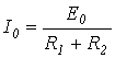 ;
;
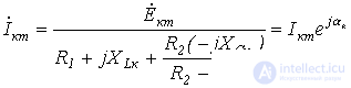 .
.
It must be remembered that, owing to the difference in frequencies, it is not permissible to sum the complex phasors of different harmonics.
Thus, the method for calculating linear circuits under non-sinusoidal currents reduces to the following:
References
Review questions
Answer:  .
.
Answer: U=218 V; P=1260 W.
Answer: I=5.5 A.
 and an inductor with
  , if the current in it is
  . Calculate the active power in the branch.
 ;
;  .
.
Comments