
Lecture
Whenever a change occurs in an electric circuit – switching on, switching off, a short circuit, a change in the value of some parameter, etc. – a transient process arises in it, which cannot take place instantaneously, since the energy stored in the circuit's electromagnetic field cannot change instantaneously. Thus, a transient process is caused by a mismatch between the amount of energy stored in the magnetic field of an inductor and the electric field of a capacitor and the value corresponding to the new state of the circuit.
Transient processes can give rise to large overvoltages, surge currents, and electromagnetic oscillations, which can disrupt the operation of a device or even cause it to fail. On the other hand, transient processes find useful practical application, for example in various kinds of electronic oscillators. All this makes it necessary to study methods for analyzing non-stationary circuit operating modes.
The main methods for analyzing transient processes in linear circuits are:
The classical method for calculating transient processes consists of directly integrating the differential equations describing the changes in currents and voltages across sections of the circuit during the transient process.
In the general case, when using the classical method of calculation, equations of the electromagnetic state of the circuit are set up using Ohm's and Kirchhoff's laws for the instantaneous values of voltages and currents, which are related to one another at individual circuit elements by the relations given in Table 1.
Table 1. Relation between the instantaneous values of voltages and currents at elements of an electric circuit
| Resistor (ideal resistance) |
|
|
| Inductor (ideal inductance) |
|
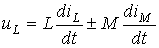
in the presence of magnetic coupling with a coil carrying current
|
| Capacitor (ideal capacitance) |
|
|
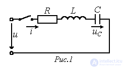
For a series circuit containing a linear resistor R, an inductor L and a capacitor C, when it is connected to a source with voltage u (see Fig. 1) we can write
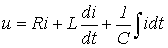 . . |
(1) |
Substituting into (1) the value of the current through the capacitor
 ,
,
we obtain a linear second-order differential equation with respect to 
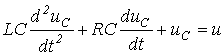 .
.
In the general case, the equation describing the transient process in a circuit with n independent energy-storage elements has the form:
 , , |
(2) |
where x is the unknown function of time (voltage, current, flux linkage, etc.);  - is the known disturbing input (the voltage and/or current of the electrical energy source);
  - is the k-th constant coefficient, determined by the circuit parameters.
The order of this equation equals the number of independent energy-storage elements in the circuit, meaning the inductors and capacitors in the simplified circuit obtained from the original one by combining the inductances and, respectively, the capacitances of elements connected in series or in parallel.
In the general case the order of the differential equation is determined by the relation
 , , |
(3) |
where  and
and  - are, respectively, the number of inductors and capacitors after the above simplification of the original circuit;
  - is the number of nodes at which only branches containing inductors meet (in this case, in accordance with Kirchhoff's first law, the current through any inductor is determined by the currents through the other inductors);
  - is the number of circuit loops whose branches contain only capacitors (in this case, in accordance with Kirchhoff's second law, the voltage across any of the capacitors is determined by the voltages across the others).
The presence of inductive coupling has no effect on the order of the differential equation.
As is known from mathematics, the general solution of equation (2) is the sum of a particular solution of the original non-homogeneous equation and the general solution of the homogeneous equation obtained from the original one by setting its left-hand side to zero. Since, from the mathematical standpoint, no restrictions are imposed on the choice of a particular solution of (2), in electrical engineering it is convenient to take as such a solution the solution  , corresponding to the desired variable x in the steady-state post-switching mode (theoretically for
  ).
).
The particular solution  of equation (2) is determined by the form of the function
  on its right-hand side, and is therefore called the forced component. For circuits with given constant or periodic source voltages (currents), the forced component is determined by calculating the steady-state operating mode of the circuit after switching, using any of the previously discussed methods for calculating linear electric circuits.
The second component  of the general solution x of equation (2) – the solution of (2) with a zero right-hand side – corresponds to the mode in which the external (forcing) forces (energy sources) do not act directly on the circuit. Here the influence of the sources is manifested through the energy stored in the fields of the inductors and capacitors. This operating mode of the circuit is called the free mode, and the variable
  - the free component.
In accordance with the above, the general solution of equation (2) has the form
 |
(4) |
Relation (4) shows that in the classical method of calculation the post-switching process is treated as the superposition of two modes – the forced mode, which sets in essentially immediately after switching, and the free mode, which occurs only during the transient process.
It must be emphasized that, since the principle of superposition holds only for linear systems, the solution method based on the above-mentioned decomposition of the unknown variable x is valid only for linear circuits.
In accordance with the definition of the free component  , its expression contains constants of integration
  , whose number equals the order of the differential equation. The constants of integration are found from the initial conditions, which are customarily divided into independent and dependent ones. The independent initial conditions include the flux linkage (current) for an inductor and the charge (voltage) on a capacitor at the instant
  (the instant of switching). The independent initial conditions are determined on the basis of the switching laws (see Table 2).
Table 2. Switching Laws
|
Name of the law |
Statement of the law |
|
First switching law (law of conservation of flux linkage) |
The magnetic flux linked with the inductors of a loop, at the instant of switching, retains the value it had before switching, and begins to change starting precisely from that value: |
|
Second switching law (law of conservation of charge) |
The electric charge on capacitors connected to any node, at the instant of switching, retains the value it had before switching, and begins to change starting precisely from that value: |
The switching laws can be proved by contradiction: if the opposite is assumed, infinitely large values of  and
and 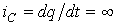 result, which leads to a violation of Kirchhoff's laws.
In practice, except for special cases (incorrect switchings), it is permissible to use these laws in another formulation, namely:
the first switching law – in a branch with an inductor, the current at the instant of
switching retains its pre-switching value and thereafter begins to change from it:  .
.
the second switching law – the voltage across a capacitor at the instant of
switching retains its pre-switching value and thereafter begins to change from it:  .
.
It must be emphasized that a more general formulation of the switching laws is the statement that a stepwise change at the instant of switching is impossible – for circuits with an inductor, of the flux linkages, and for circuits with capacitors, of the charges on them. Illustrations of this can be found in the circuits of Fig. 2, whose transient processes belong to the so-called incorrect switchings (the name arises from neglecting small parameters in such circuits, a correct accounting of which could substantially complicate the problem).
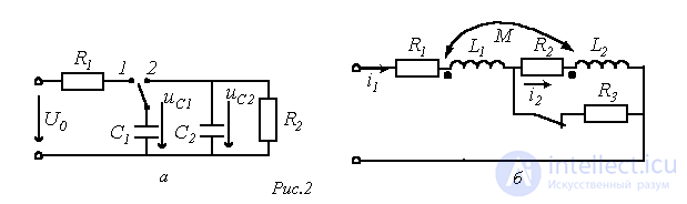
Indeed, when the switch in the circuit of Fig. 2,a is moved from position 1 to position 2, interpreting the second switching law as the impossibility of a stepwise change in the voltage across the capacitor leads to a violation of Kirchhoff's second law  . Similarly, when the switch in the circuit of Fig. 2,b is opened, interpreting the first switching law as the impossibility of a stepwise change in the current through the inductor leads to a violation of Kirchhoff's first law
 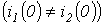 . For these circuits, based on conservation of charge and, respectively, flux linkage, we can write:

Dependent initial conditions are the values of the remaining currents and voltages, as well as the derivatives of the unknown function at the instant of switching, determined from the independent initial conditions by means of equations set up using Kirchhoff's laws for  . The required number of initial conditions equals the number of integration constants. Since an equation of the form (2) is conveniently written for the variable whose initial value belongs to the independent initial conditions, the task of finding the initial conditions is usually reduced to finding the values of this variable and its derivatives up to and including order (n-1) at
  .
.
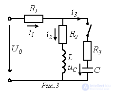
Example. Determine the currents and derivatives  and
and  at the instant of switching in the circuit of Fig. 3, if the capacitor was uncharged before switching.
In accordance with the switching laws
 and
and 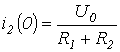 .
.
Based on Kirchhoff's second law, at the instant of switching we have
 ,
,
from which
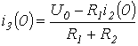
and  .
.
For the known values  and
and  , from the equation

we determine  .
.
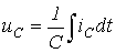
The value of the derivative of the voltage across the capacitor at the instant of switching (see Table 1)
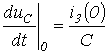 .
.
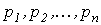
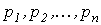
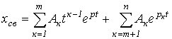
The expression for the free component  of the general solution x of the differential equation (2) is determined by the form of the roots of the characteristic equation (see Table 3).
Table 3. Expressions for the free components of the general solution
|
Form of the roots of the characteristic equation |
Expression for the free component |
|
Roots |
|
|
Roots |
|
|
Pairs of complex-conjugate roots |
|
It must be remembered that, since in a linear circuit the free component decays over time, the real parts of the roots of the characteristic equation cannot be positive.
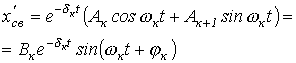
For real roots  decays monotonically, and an aperiodic transient process takes place. The presence of a pair of complex-conjugate roots gives rise to damped sinusoidal oscillations (an oscillatory transient process).
Since the oscillatory process is physically associated with a periodic exchange of energy between the magnetic field of the inductor and the electric field of the capacitor, complex-conjugate roots can occur only for circuits containing both types of energy-storage elements. The rate of decay of the oscillations is customarily characterized by the ratio
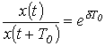 ,
,
which is called the decrement of oscillation, or by the natural logarithm of this ratio
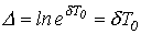 ,
,
called the logarithmic decrement of oscillation, where  .
.
An important characteristic when studying transient processes is the time constant t, defined for first-order circuits as:
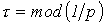 ,
,
where p – is the root of the characteristic equation.
The time constant can be interpreted as the time interval during which the free component decreases by a factor of e compared to its initial value. Theoretically the transient process lasts indefinitely. In practice, however, it is considered to end at 
 and
and  - from an energy standpoint.
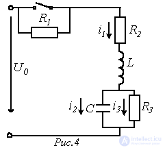
 and the voltages
  on the capacitor and
  on the inductor at the instant of switching in the circuit of Fig. 4, if
  .
.
Answer:

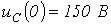 ;
;
 .
.

 ;
; ,
,
 ;
;
 .
. .
. real and distinct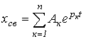
 real and


Comments