
Lecture
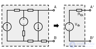
Thévenin's Theorem (the Thévenin theorem, the Thévenin—Helmholtz theorem) — a statement that any source can be equivalently replaced by a series-connected ideal voltage source and internal resistance; it is the dual statement to Norton's theorem on the equivalent replacement of an arbitrary circuit by a parallel-connected ideal current source and resistor.
First formulated by Hermann von Helmholtz in 1853, and independently by the French electrical engineer Léon Charles Thévenin (fr. Léon Charles Thévenin) in 1883
Online simulation of the theorem
For linear electrical circuits, the theorem states that any electrical circuit having two terminals and consisting of an arbitrary combination of voltage sources, current sources, and resistors (resistances) is, electrically, equivalent at these two terminals to a circuit with a single ideal voltage source with EMF  and a single resistor
  , connected in series with this voltage source.
In other words, the current in any resistance  connected to any circuit is equal to the current in this same resistance when connected to an ideal voltage source with a voltage equal to the open-circuit voltage of the circuit (the voltage at these terminals when nothing is connected to them) and having internal resistance
  , equal to the total resistance of the «closed part» of the circuit, as determined from the side of terminals , provided that all sources inside the circuit are replaced by full resistances equal to the internal full resistances of these sources.
That is, experimentally, the parameters of the equivalent replacement of a two-terminal «black box» are determined from two measurements — the open-circuit test and the short-circuit test. Let the voltage at the terminals under open-circuit conditions be  and the current under short-circuit conditions at these same terminals be
  then:
then:
 and
and 
where  — is the EMF of the ideal voltage source in the equivalent replacement,
 — is the resistance of the resistor connected in series with the source in the equivalent replacement.
If the structure and parameters of a given circuit are known, the parameters of the equivalent replacement can be formally calculated. In this analysis, when calculating the equivalent resistance, all ideal voltage sources in the circuit are mentally short-circuited, and the resistance of the resulting circuit is calculated with respect to the terminals under consideration. Then, using, for example, Kirchhoff's rules, the voltage at the terminals is calculated. The resulting resistance and voltage are precisely the parameters of the equivalent replacement.
The theorem is also applicable to sinusoidal AC circuits in steady state, but in this case it is not the active resistances, currents, and voltages that are taken into account, but rather the impedances and the complex amplitudes of the currents and voltages, respectively.
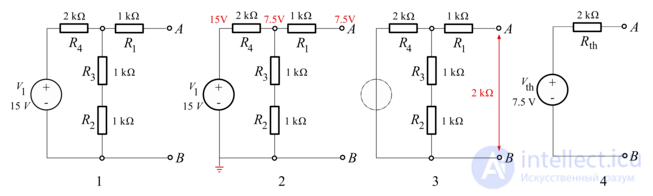
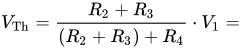
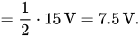
Calculation of the equivalent voltage (EMF) — the voltage taken from a resistive voltage divider consisting of resistances  , since the open-circuit condition is being calculated, the current through resistor
  and the voltage drop across it are zero:

Calculating the equivalent resistance, with the voltage source shorted:



Here the symbol  denotes the resistance of the parallel combination of resistors
  and
and 

Comments