
Lecture
The zero-sequence impedance of elements differs substantially from the positive- and negative-sequence impedances, since mutual inductance behaves differently in this case, and, moreover, the zero-sequence impedance depends on the phase-connection scheme of the element in question and on whether the neutral is grounded.
In synchronous machines with a grounded neutral, zero-sequence currents flow that produce magnetic fluxes equal in magnitude and coincident in time. Since the phase windings of the machine are displaced by 1200 around the circumference of the rotor, the zero-sequence magnetic fluxes of the machine are likewise displaced in space relative to one another by 1200. Therefore, it can be considered that the resultant zero-sequence magnetic flux in the machine's air gap is equal to zero and produces no rotor reaction.
The zero-sequence reactance of synchronous machines is determined by the leakage of the magnetic flux in the slots and end windings, and its value is smaller than for a symmetrical three-phase flux, and it strongly depends on the type of winding. For this reason, the value of x0 for synchronous machines varies over a wide range:
x0=(0.15…0.6)x”d. 6.5
Since synchronous machines are practically always operated with an isolated neutral, zero-sequence currents do not flow in them, so x0 = ∞.
+The zero-sequence reactance of induction motors, as with synchronous machines, is determined solely by the leakage of the stator winding and depends to a greater extent on its type and construction. Sufficiently reliable values of this impedance can be obtained experimentally or from manufacturer's data.
The zero-sequence impedance of transformers depends on their construction (single-phase, three-phase three-leg, three-phase four-leg, etc.) and on the winding connection scheme (delta, star with grounded neutral point, star with ungrounded neutral point). On the side of a winding connected in delta or in an ungrounded star, regardless of how the other windings are connected, the zero-sequence impedance is equal to infinity. The zero-sequence impedance of transformers on the side of a winding connected in a star with a grounded neutral depends on the connection scheme of the other windings and on the presence, in their circuits, of loops for the passage of zero-sequence currents.
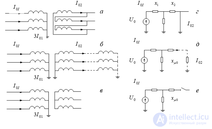
Fig. 6.3. Winding connections of transformers and their equivalent circuits for zero-sequence currents.
Fig. 6.2, a, c show the main variants of winding connection for a two-winding transformer, in which a zero-sequence voltage applied to winding I causes a current of the same sequence to flow in one or both windings. On the right, opposite each winding-connection variant, are shown the transformer's equivalent circuits for zero-sequence currents (xI and xII – leakage reactances of windings I and II; xM - magnetizing reactance for zero sequence of the transformer).
When the windings are connected according to the Y0 / Δ ( Fig. 6.2,a ) the zero-sequence EMF of the transformer is entirely consumed in driving a current of the same sequence through the leakage reactance of the delta-connected winding, since this current (similar to the third current harmonic) does not go beyond the bounds of that winding. In the equivalent circuit, this is represented by short-circuiting the branch with xII .
Since the impedance xM0 is considerably larger in value than the impedance xII , the effect of the shunt xM0 is disregarded.
Thus, the zero-sequence impedance for windings connected according to the schemeY0 / Δ is, regardless of the transformer's construction, equal to the positive-sequence impedance
x0 ≈ xI + xII = x1.
When the windings are connected according to the scheme Y0 /Y0 , according to its equivalent circuit (Fig. 6.2,b) it is assumed that on the side of winding II a path is provided for the zero-sequence current, i.e. the circuit of winding II has, at the very least, one more grounded neutral (see the dashed line). If this is not the case, the equivalent circuit will be the same as for windings connected according to the scheme Y0 / Y0 (Fig. 6.2,c), which corresponds to the no-load condition of the transformer, under which
x0 ≈ xII + xM0 .
Here the value of xM0 depends on the transformer's construction.
The magnetizing reactance of a three-phase three-leg transformer depends on its construction and amounts to xM0 = 0.3 …1.0 . For all other transformer constructions, it can be taken that xM0 = ∞ .
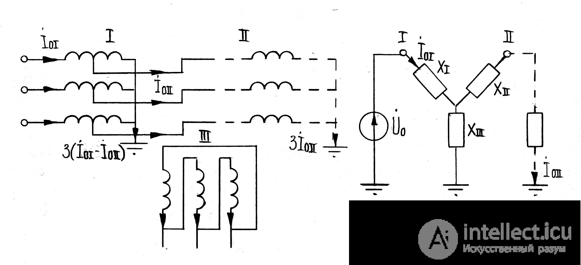
Fig. 6.4. Winding connection of an autotransformer and its equivalent circuit for zero-sequence currents
In three-winding transformers, one of the windings is, as a rule, delta-connected. Therefore, for these it can always be taken that xM0 = ∞ . The main variants of winding connection and their corresponding zero-sequence equivalent circuits are shown in Fig. 6.3,d,e,f.
The equivalent circuit of an autotransformer for zero-sequence currents (Fig. 6.4) has the same form as for a three-winding transformer with the corresponding winding connection. The current in the autotransformer's neutral, when it is solidly grounded, is
İN = 3 ( İ0I – İ0II),
+where İ0I and İ0II – zero-sequence currents of the primary and secondary circuits, each of which must be referred to its own voltage level.
[[b8465]]

Comments