
Lecture
Three-phase circuits are a type of sinusoidal-current circuit, and therefore all previously considered methods of calculation and analysis in complex (phasor) form fully apply to them. It is convenient to analyze three-phase systems using phasor diagrams, which make it fairly simple to determine the phase shifts between variables. However, certain specifics of polyphase circuits introduce characteristic features into their calculation, which primarily concerns the analysis of their operation in symmetrical (balanced) modes.
Calculation of balanced operating modes of three-phase systems
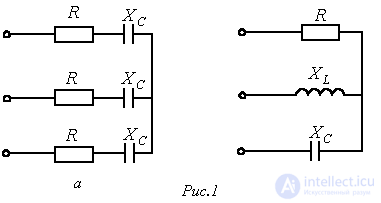
A polyphase load, and a polyphase circuit in general, is called symmetrical (balanced) if the complex impedances of the corresponding phases are equal, i.e., if  . Otherwise it is unbalanced. Equality of the magnitudes of these impedances is not a sufficient condition for circuit balance. For example, the three-phase load in Fig. 1,a is balanced, while the one in Fig. 1,b is not, even under the condition:
 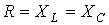 .
.
If a balanced three-phase system of generator voltages is applied to a balanced three-phase circuit, a balanced system of currents will occur in it. Such an operating mode of a three-phase circuit is called balanced (symmetrical). In this mode, the currents and voltages of the corresponding phases are equal in magnitude and are phase-shifted relative to one another by an angle  . Because of this, the calculation of such circuits is carried out for a single – base – phase, which is usually taken to be phase A. The corresponding quantities in the other phases are then obtained by formally adding the phase shift
  to the argument of the phase-A variable, while keeping its magnitude unchanged.
Thus, for the balanced operating mode of the circuit in Fig. 2,a, given the line voltage and phase impedances  , we can write
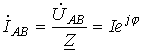 ,
,
where  is determined by the nature of the load
  .
.
Then, on the basis of the above,
 ;
;
 .
.
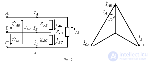
The complex line currents can be found using the phasor diagram in Fig. 2,b, from which it follows that:
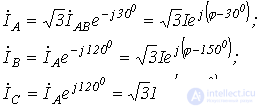
When analyzing complex circuits operating in a balanced mode, the calculation is carried out using two main techniques:
All delta connections are replaced with equivalent star connections. Since the deltas are balanced, according to the delta-to-star transformation formulas  .
.
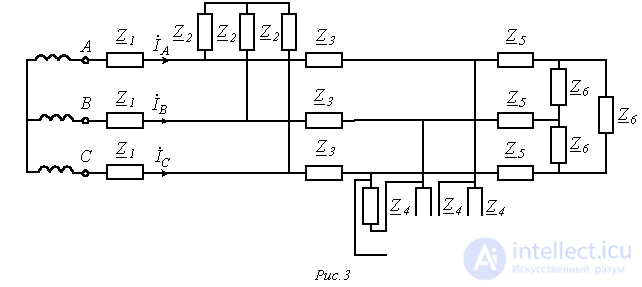
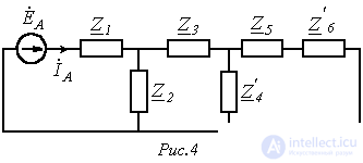
Since all the original and newly obtained load stars are balanced, the potentials of their neutral points are equal. Consequently, without changing the circuit's operating mode, they can (mentally) be connected by a neutral wire. After this, the base phase (usually phase A) is isolated from the circuit, and the calculation is carried out for it, from the results of which the corresponding quantities in the other phases are determined.
Suppose, for example, that for a given phase voltage  it is necessary to determine the line currents
  and
and  in the circuit of Fig. 3, all of whose impedances are known.
Following the method described, let us isolate the calculation phase A, shown in Fig. 4. Here  ,
,  .
.
Then for the current  we can write
 ,
,
and correspondingly  .
.
Calculation of unbalanced operating modes of three-phase systems
If at least one of the balance conditions is not satisfied, the three-phase circuit is operating in an unbalanced mode. Such modes, when the circuit contains only a static load and the voltage drop in the generator is neglected, are calculated for the circuit as a whole by any of the previously considered calculation methods. In this case, the generator's phase voltages are replaced with corresponding EMF sources. It may be noted that, since in polyphase circuits, besides currents, node potentials are also usually of interest, the node-potential method is most often used to calculate complex circuits. For analyzing unbalanced operating modes of three-phase circuits containing electrical machines, the method of symmetrical components is mainly used, which will be considered further on.
Given line voltages, three-phase circuits with a delta connection are the easiest to calculate. Suppose that in the circuit of Fig. 2,a  . Then, given the complex line voltages, by Ohm's law
 ;
;  ;
;  .
.
From the found phase currents of the load, the line currents are determined based on Kirchhoff's first law:
 .
.
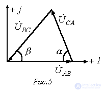
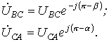
In practice, it is usually not the complex line voltages that are known, but only their magnitudes. In this case, a preliminary determination of the initial phases of these voltages is required, which can be done, for example, graphically. To do this, taking 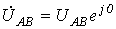 , and using the given voltage magnitudes, we construct a triangle (see Fig. 5), from which (by measurement) we determine the values of angles a and b.
Then
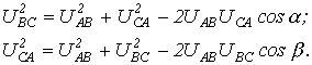
The required angles a and b can also be found analytically on the basis of the law of cosines:
When the generator and load phases are connected in a star with a zero-resistance neutral wire, the phase voltages of the load equal the corresponding voltages on the source phases. In this case, the phase currents are easily determined by Ohm's law, i.e., by dividing the known voltages on the load phases by the corresponding impedances. However, if the resistance of the neutral wire is large, or it is absent, a more complex calculation is required.
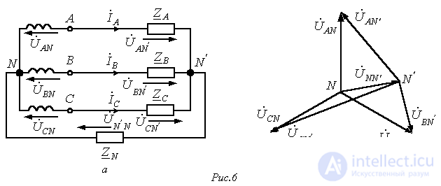
Consider the three-phase circuit in Fig. 6,a. Under balanced supply and unbalanced load  , the voltage phasor diagram corresponding to it (see Fig. 6,b) will, in the general case, show the neutral points of the source and load occupying different positions, i.e.,
  .
.
The potential difference between the neutral points of the generator and the load is called the neutral-point displacement voltage (it is usually assumed that  ), or simply the neutral displacement voltage. The larger it is, the stronger the imbalance of the phase voltages on the load, as clearly illustrated by the phasor diagram in Fig. 6,b.
To calculate the currents in the circuit of Fig. 6,a, the neutral displacement voltage must be known. If it is known, the voltages on the load phases are:
 .
.
Then for the required currents we can write:
 .
.
The relation for the neutral displacement voltage, written on the basis of the node-potential method, has the form
 . . |
(1) |
With a zero-resistance neutral wire present,  , and from (1)
  . If the neutral wire is absent,
  . With a balanced load
  , taking into account that
  , it follows from (1) that
  .
.
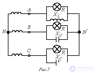
As an example of analyzing an unbalanced operating mode of a circuit using relation (1), let us determine which of the lamps in the circuit of Fig. 7, with direct phase rotation of the source, will burn brighter if 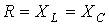 .
.
Let us write the expressions for the complex impedances of the load phases:
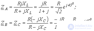
Then for the neutral displacement voltage we obtain
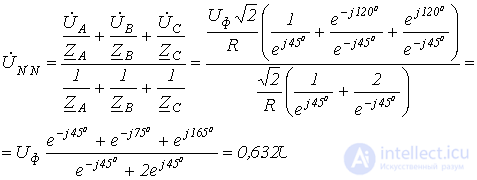
The voltages on the load phases (hereafter the index N on the source phase voltages is omitted)
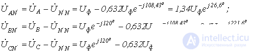
Thus, the lamp in phase C will burn the brightest.
Finally, we note that if, for a star connection, the line voltages are given (as is usually the case in practice), then, taking into account that their sum equals zero, they can be uniquely specified using two EMF sources, for example,  and
and  . Then, since in this case
  , relation (1) is transformed into the formula
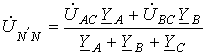 . . |
(2) |
References
Review Questions and Problems
Determine the current in the neutral wire.
Answer: 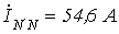 .
.
Determine the current in the neutral wire.
Answer: 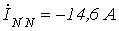 .
.
Determine the phase voltages on the load.
Answer: 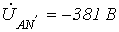 ;
;  ;
;  .
.
Determine the phase voltages on the load.
Answer: 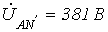 ;
;  ;
;  .
.
 ;
;  ;
;  ;
;  . The line voltage is 380 V.
 ;
;  . The other parameters are the same.
Comments