
Lecture 2 min.
In complex electrical circuits, that is, where there are several diverse branches and several EMF sources, a complex distribution of currents takes place. However, given known values of all the EMFs and resistances of the resistive elements in the circuit, we can determine the values of these currents and their direction in any loop of the circuit using Kirchhoff's first and second laws. The rules were formulated in 1845; this is not Kirchhoff's only discovery. Kirchhoff and Bunsen actively studied the emission spectra of chemical elements, using Fraunhofer's inventions. Using a prism or diffraction grating, light was decomposed into spectral components, and the scientists observed the effect. In this way the individual frequencies of a number of elements of Mendeleev's table were established. These scientists laid the foundations of spectroscopy. Kirchhoff devoted a great deal of time to various branches of science. For example, he found an error in the formulation of the boundary conditions for solving the differential equations for membrane vibrations presented to the public in 1811 by Sophie Germain. One should not think that the phrase Kirchhoff's law is narrowly limited to two rules, one of which directly leads to the previously formulated Ohm's law.
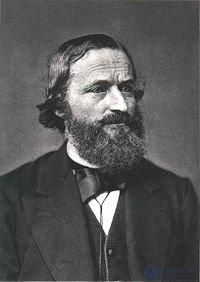
| German: Gustav Robert Kirchhoff | |
 |
|
| Date of birth | March 12, 1824 |
|---|
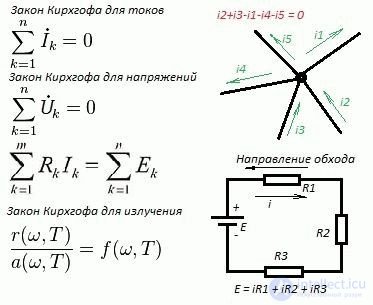
An example of a complex electrical circuit can be seen in Figure 1.
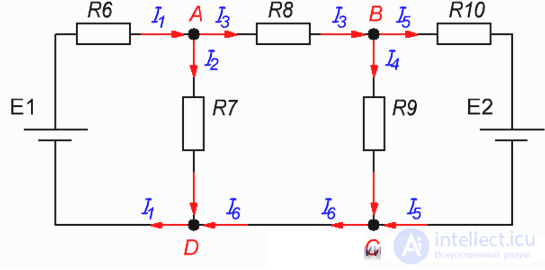
Figure 1. A complex electrical circuit.
Kirchhoff's laws are sometimes called Kirchhoff's rules, especially in older literature.
So, to begin with, let me recall the essence of Kirchhoff's first and second laws, and then we will look at examples of calculating currents and voltages in electrical circuits, with practical examples and answers to questions that have been asked of me in the comments on the site.
The most accurate method, but it can be used to determine the parameters of a circuit with a small number of loops (1-3).
Algorithm:
1. Determine the number of nodes q, branches p and independent loops;
2. Assign the directions of currents and loop traversals arbitrarily;
3. Establish the number of independent equations according to Kirchhoff's first law (q - 1) and write them out, where q is the number of nodes;
4. Determine the number of equations according to Kirchhoff's second law (p – q + 1) and write them out;
5. Solving the equations together, we determine the missing circuit parameters;
6. The calculations obtained are then checked by substituting the values into the equations for Kirchhoff's first and second laws, or by drawing up and calculating the power balance.
Example:
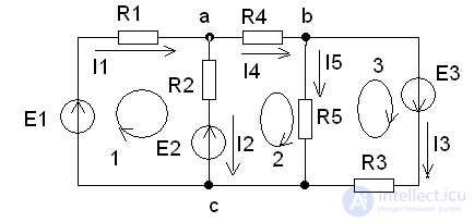
Fig. 1. According to the proposed algorithm, let us determine the number of nodes and branches of the circuit in Fig. 1
q = 3, p = 5, therefore, the number of equations according to Kirchhoff's first law equals 2, and the number of equations according to Kirchhoff's second law equals 3.
Let us write these equations according to the rules:
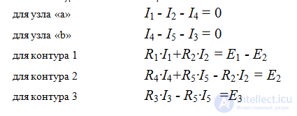
Let us draw up the power balance equations:

Kirchhoff's rules (often called Kirchhoff's laws in technical literature) — relations that hold between the currents and voltages in the branches of any electrical circuit.
Solving the systems of linear equations formulated on the basis of Kirchhoff's rules makes it possible to find all the currents and voltages in DC, AC and quasi-stationary current electrical circuits .
They are of particular importance in electrical engineering because of their universality, as they are suitable for solving many problems in the theory of electrical circuits and for practical calculations of complex electrical circuits.
Applying Kirchhoff's rules to a linear electrical circuit makes it possible to obtain a system of linear equations with respect to currents or voltages and, accordingly, when solving this system, to find the values of the currents in all branches of the circuit and all the inter-node voltages.
Formulated by Gustav Kirchhoff in 1845 .
The name «Rules» is more accurate, because these rules are not fundamental laws of nature but follow from the fundamental laws of conservation of charge and the irrotational nature of the electrostatic field (Maxwell's third equation for an unchanging magnetic field). These rules should not be confused with two other laws of Kirchhoff in chemistry and physics.
Formulation No. 1: The sum of all currents flowing into a node equals the sum of all currents flowing out of the node.
Formulation No. 2: The algebraic sum of all currents at a node equals zero.
[[s|kirgof1.txt]]
Let us illustrate Kirchhoff's first law using the example in Figure 2.
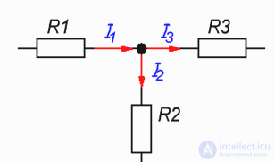
Figure 2. Node of an electrical circuit.
Here current I1- is the current flowing into the node, while currents I2 and I3 — are the currents flowing out of the node. Then, applying Formulation No. 1, we can write:
I1 = I2 + I3 (1)
To confirm the validity of Formulation No. 2, let us move the currents I2 and I3 to the left-hand side of expression (1), thereby obtaining:
I1 - I2 - I3 = 0 (2)
The «minus» signs in expression (2) indicate that the currents are flowing out of the node.
The signs for incoming and outgoing currents can be chosen arbitrarily; however, incoming currents are usually always taken with a «+» sign, and outgoing currents with a «-» sign (as, for example, turned out in expression (2)).
Formulation: The algebraic sum of the EMFs acting in a closed loop equals the algebraic sum of the voltage drops across all resistive elements in that loop.
[[s|kirgof2.txt]]
Here the term «algebraic sum» means that both the EMF value and the voltage drop across the elements can have either a «+» or a «-» sign. The sign can be determined using the following algorithm:
1. Choose the direction of loop traversal (two options: either clockwise or counterclockwise).
2. Arbitrarily choose the direction of the currents through the circuit elements.
3. Assign signs to the EMFs and the voltage drops across the elements according to the rules:
- EMFs that create a current in the loop whose direction coincides with the direction of loop traversal are written with a «+» sign; otherwise, the EMF is written with a «-» sign.
- voltages dropped across circuit elements are written with a «+» sign if the current flowing through these elements coincides in direction with the loop traversal; otherwise, the voltage is written with a «-» sign.
For example, let us consider the circuit shown in Figure 3, and write an expression according to Kirchhoff's second law, traversing the loop clockwise and choosing the direction of the currents through the resistors as shown in the figure.
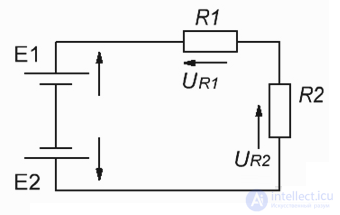
Figure 3. Electrical circuit illustrating Kirchhoff's second law.
E1- E2 = -UR1 - UR2 or E1 = E2 - UR1 - UR2 (3)
Now let us consider a more complex circuit, and I will show you how to apply Kirchhoff's laws in practice.
So, in Figure 4 there is a complex circuit with two EMF sources of magnitude E1=12 V and E2=5 V , with internal source resistance r1=r2=0,1 Ω, operating into a common load R = 2 Ω. We now need to determine how the currents will be distributed in this circuit and what values they have.
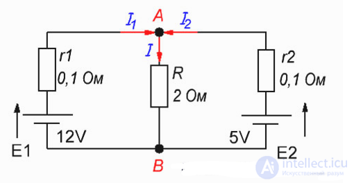
Figure 4. Example of calculating a complex electrical circuit.
Now, according to Kirchhoff's first law, for node A we write the following expression:
I = I1 + I2,
since I1 and I2 flow into node A, while current I flows out of it.
Using Kirchhoff's second law, let us write two more expressions for the outer loop and the inner left loop, choosing the clockwise direction of traversal.
For the outer loop:
E1-E2 = Ur1 – Ur2 or E1-E2 = I1*r1 – I2*r2
For the inner left loop:
E1 = Ur1 + UR or E1 = I1*r1 + I*R
So we get a system of three equations with three unknowns:
I = I1 + I2;
E1-E2 = I1*r1 – I2*r2;
E1 = I1*r1 + I*R.
Now let us substitute the known voltage and resistance values into this system:
I = I1 + I2;
7 = 0.1I1 – 0.1I2;
12 = 0.1I1 +2I.
Next, from the first and second equations let us express the current I2
I2=I - I1;
I2 = I1 – 70;
12 = 0.1I1 + 2I.
As the next step, let us equate the first and second equations and obtain a system of two equations:
I - I1= I1 – 70;
12 = 0.1I1 + 2I.
Let us express I from the first equation
I = 2I1– 70;
And substitute its value into the second equation
12 = 0.1I1 + 2(2I1 – 70).
Let us solve the resulting equation
12 = 0.1I1 + 4I1 – 140.
12 + 140= 4.1I1
I1=152/4.1
I1=37.073 (A)
Now, into the expression I = 2I1– 70 let us substitute the value
I1=37.073 (A) and we get:
I = 2*37.073 – 70 = 4.146 A
Well, according to Kirchhoff's first law the current I2=I - I1
I2=4.146 - 37.073 = -32.927
The «minus» sign for current I2 means that we chose the direction of the current incorrectly, that is, in our case the current I2 flows out of node A.
The data obtained can now be checked in practice or by simulating this circuit, for example in Multisim.
You can see a screenshot of the circuit simulation used to verify Kirchhoff's laws in Figure 5.
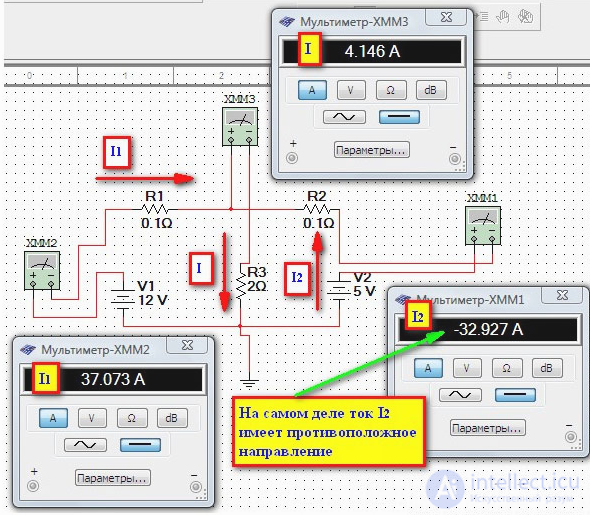
Figure 5. Comparison of the calculation results and the circuit simulation results.
Kirchhoff's rules are of an applied nature and, together with other techniques and methods (the equivalent generator method, the superposition principle, the potential diagram method), allow electrical engineering problems to be solved. Kirchhoff's rules have found wide application thanks to the simplicity of formulating the equations and the possibility of solving them by standard methods of linear algebra (Cramer's method, the Gauss method, etc.).
Kirchhoff's law of radiation states that the ratio of the emissive power of any body to its absorptive power is the same for all bodies at a given temperature, for a given frequency, for equilibrium radiation, and does not depend on their shape, chemical composition, etc.
In its modern formulation, the law reads as follows:
The ratio of the emissive power of any body to its absorptive power is the same for all bodies at a given temperature, for a given frequency, and does not depend on their shape or chemical nature.
It is known that when electromagnetic radiation falls on a certain body, part of it is reflected, part is absorbed, and part may be transmitted. The fraction of the incident radiation absorbed at a given frequency is called the absorptive power of the body  . On the other hand, every heated body radiates energy according to a certain law, called the emissive power of the body
  .
.
The quantities and can vary greatly from one body to another; however, according to Kirchhoff's law of radiation, the ratio of the emissive and absorptive powers does not depend on the nature of the body and is a universal function of frequency (wavelength) and temperature:
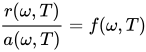
By definition, an absolutely black body absorbs all radiation incident on it, that is, for it  . Therefore the function
  coincides with the emissive power of an absolutely black body, described by Planck's formula, as a result of which the emissive power of any body can be found based solely on its absorptive power.
Real bodies have an absorptive power less than unity, and consequently also a lower emissive power than an absolutely black body. Bodies whose absorptive power does not depend on frequency are called gray bodies. Their spectrum has the same shape as that of an absolutely black body. In the general case, however, the absorptive power of bodies depends on frequency and temperature, and their spectrum can differ substantially from that of an absolutely black body. The study of the emissive power of different surfaces was first carried out by the Scottish scientist Leslie using his own invention — the Leslie cube.
In theoretical studies, it is more convenient to characterize the spectral composition of equilibrium thermal radiation using the function of frequency . In experimental work, it is more convenient to use the function of wavelength  . The two functions are related to each other by the formula

In astrophysics, Kirchhoff's law is often applied in the following form:
 ,
,
where  — is the emission coefficient (the energy radiated by a unit volume in a unit frequency interval into a unit solid angle per unit time);
  — is the absorption coefficient taking stimulated emission into account (
 , where
  — is the density of the substance, and
  and
and  — are, respectively, the opacity and the effective photon path length for frequency
  );
);  — is the radiation intensity of an absolutely black body.
Kirchhoff's law is valid only for cases of thermal equilibrium. However, it is often applied to non-equilibrium systems as well, when the radiation is not in equilibrium with the matter and its frequency distribution differs substantially from the Planckian one. In such cases, the assumption of thermodynamic equilibrium among the particles of the radiating substance often (but not always) turns out to be a good approximation. The degree of deviation from Kirchhoff's law can serve as a measure of how different the radiation of cosmic objects is from thermal radiation.
Kirchhoff's law states that the temperature coefficient of the heat effect of a chemical reaction is equal to the change in heat capacity of the system during the reaction.
The differential form of the law:
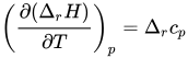
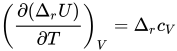
The integral form of the law:
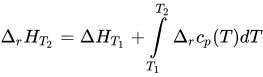
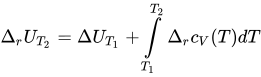
where  and
and  — are the isobaric and isochoric heat capacities,
  — is the difference between the isobaric heat capacities of the reaction products and the starting substances,
  — is the difference between the isochoric heat capacities of the reaction products and the starting substances, and
  and
and  — are the corresponding heat effects.
If the difference  is small, then one can take
 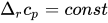 and
and  , and accordingly the integral form of the equations takes the following form:


For a large temperature difference, the temperature dependence of the heat capacities must be taken into account: 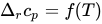 and
and 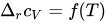

Comments