
Lecture
Rotating magnetic field. A rotating magnetic field is usually understood to be a magnetic field whose magnetic-flux-density vector, without changing in magnitude, rotates at a constant angular velocity.
Rotating magnetic fields also refer to the magnetic fields of rotating permanent magnets.
There exist rotating magnetic fields whose axis of rotation does not coincide with their axis of symmetry (for example, the magnetic fields of stars or planets).
A rotating magnetic field is created by superposing two or more differently oriented alternating magnetic fields, varying with time according to a sinusoidal law, of the same frequency but shifted in phase relative to one another.
The rotating magnetic field was independently realized in practice in 1888 by the Italian physicist G. Ferraris and the Serbian engineer N. Tesla .
As shown earlier, one of the most important advantages of polyphase systems is that a rotating magnetic field can be obtained using stationary coils, which is the basis for the operation of AC motors. We begin the discussion of this question with an analysis of the magnetic field of a coil carrying a sinusoidal current.
Magnetic field of a coil carrying a sinusoidal current
When a sinusoidal current is passed through the winding of a coil, it creates
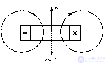
a magnetic field whose flux-density vector varies (pulsates) along the coil, also according to a sinusoidal law. The instantaneous orientation of the magnetic-flux-density vector in space depends on the winding of the coil and the instantaneous direction of the current in it, and is determined by the right-hand-screw rule. Thus, for the case shown in Fig. 1, the magnetic-flux-density vector is directed upward along the coil axis. After half a period, when, at the same magnitude, the current reverses sign, the flux-density vector, at the same absolute magnitude, changes its orientation in space by 180°. In view of this, the magnetic field of a coil carrying a sinusoidal current is called a pulsating field.
Circular rotating magnetic field
of two-phase and three-phase windings
A circular rotating magnetic field is a field whose magnetic-flux-density vector, without changing in magnitude, rotates in space at a constant angular frequency.
To create a circular rotating field, two conditions must be met:
Let us consider obtaining a circular rotating magnetic field for the case of a two-phase Tesla system (Fig. 2,a).
When harmonic currents are passed through the coils, each of them, in accordance with the above, creates a pulsating magnetic field. The vectors  and
and  , characterizing these fields, are directed along the axes of the respective coils, and their amplitudes also vary according to a harmonic law. If the current in coil B lags the current in coil A by 900 (see Fig. 2,b), then
  .
.
Let us find the projections of the resultant magnetic-flux-density vector  onto the x and y axes of a Cartesian coordinate system tied to the axes of the coils:

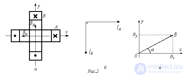
The magnitude of the resultant magnetic-flux-density vector, in accordance with Fig. 2,c, is equal to

and for the tangent of the angle a formed by this vector with the abscissa axis we can write
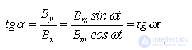 ,
,
from which
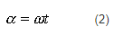
The resulting relations (1) and (2) show that the resultant magnetic field vector is constant in magnitude and rotates in space at a constant angular frequency  , describing a circle, which corresponds to a circular rotating field.
Let us show that a symmetrical three-phase system of coils (see Fig. 3,a) also makes it possible to obtain a circular rotating magnetic field.
Each of coils A, B and C, when harmonic currents are passed through them, creates a pulsating magnetic field. A spatial vector diagram for these fields is shown in Fig. 3,b. For the projections of the resultant magnetic-flux-density vector onto
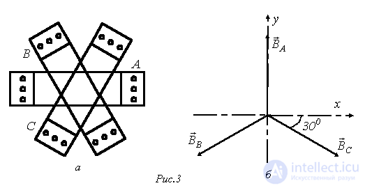
the axes of a Cartesian coordinate system, whose y-axis is aligned with the magnetic axis of phase A, we can write
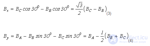
The relations given take into account the spatial arrangement of the coils, but the coils are also fed by a three-phase system of currents shifted in time phase by 120°. Therefore, for the instantaneous values of the coil flux densities, the following relations hold
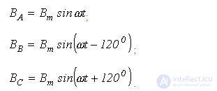
Substituting these expressions into (3) and (4), we obtain:
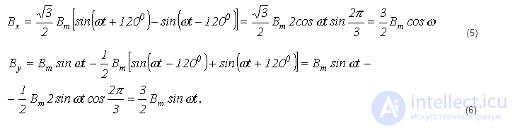
In accordance with (5) and (6) and Fig. 2,c, for the magnitude of the resultant magnetic-flux-density vector of the three current-carrying coils we can write:
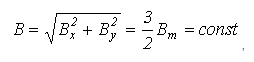 ,
,
and the vector  itself makes an angle a with the x-axis, for which
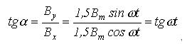 ,
,
from which
 .
.
Thus, in this case too, the magnetic-flux-density vector is constant in magnitude and rotates in space at a constant angular frequency  , which corresponds to a circular field.
Magnetic field in an electrical machine
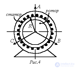
In order to strengthen and concentrate the magnetic field in an electrical machine, a magnetic circuit is created for it. An electrical machine consists of two main parts (see Fig. 4): a stationary stator and a rotating rotor, made respectively in the form of a hollow and a solid cylinder.
Three identical windings are arranged on the stator, whose magnetic axes are shifted around the bore of the magnetic core by 2/3 of a pole pitch  , the magnitude of which is determined by the expression
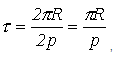 ,
,
where R is the radius of the magnetic-core bore, and p – the number of pole pairs (the number of equivalent rotating permanent magnets creating the magnetic field – in the case shown in Fig. 4, p = 1).
In Fig. 4 the solid lines (A, B and C) mark the positive directions of the pulsating magnetic fields along the axes of windings A, B and C.
Taking the magnetic permeability of the steel to be infinitely large, let us construct the distribution curve of the magnetic flux density in the machine's air gap, created by the phase-A winding, for a certain instant of time t (Fig. 5). In constructing it we take into account that the curve changes abruptly at the locations of the coil sides, while over the sections free of current there are horizontal segments.
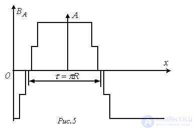
Let us replace this curve with a sinusoid (it should be noted that, in real machines, owing to the corresponding design of the phase windings, this replacement introduces only very small errors for the resultant field). Taking the amplitude of this sinusoid for the chosen instant t to be equal to BA, we write
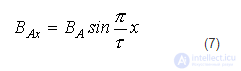
and similarly
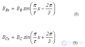
Taking into account the harmonically varying phase currents, for the instantaneous values of these quantities, under the previously made assumption of a linear relationship between flux density and current, we can write
 .
.
Substituting the last relations into (7)…(9), we obtain
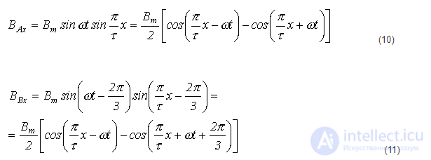
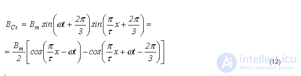
Summing relations (10)…(12), and taking into account that the sum of the last terms on their right-hand sides is identically equal to zero, we obtain for the resultant field along the machine's air gap the expression
 ,
,
which represents the equation of a traveling wave.
The magnetic flux density  is constant if
  . Thus, if we mentally choose a certain point in the air gap and move it along the bore of the magnetic core at the speed
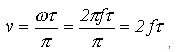 ,
,
then the magnetic flux density at this point will remain unchanged. This means that, as time passes, the magnetic flux density distribution curve moves along the circumference of the stator without changing its shape. Consequently, the resultant magnetic field rotates at a constant speed. This speed is conventionally expressed in revolutions per minute:
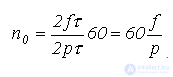 .
.
Operating principle of asynchronous and synchronous motors
The design of an asynchronous (induction) motor corresponds to the illustration in Fig. 4. The rotating magnetic field, created by the current-carrying windings located on the stator, interacts with the rotor currents, setting it into rotation. At present the most widespread type is the squirrel-cage induction motor, owing to its simplicity and reliability. In the slots of the rotor of such a machine, current-carrying copper or aluminum bars are placed. The ends of all the bars at both faces of the rotor are joined by copper or aluminum rings, which short the bars together. This is where the name of the rotor comes from.
In the short-circuited rotor winding, under the action of the EMF induced by the rotating stator field, eddy currents arise. Interacting with the field, they carry the rotor into rotation at a speed , which is fundamentally lower than the field's rotational speed 0. Hence the name of the motor – asynchronous (induction).
The quantity
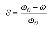
is called the relative slip. For motors of standard design, S = 0.02…0.07. The inequality between the speeds of the magnetic field and the rotor becomes obvious if we consider that, at  , the rotating magnetic field would not cut across the rotor's current-carrying bars and, consequently, no currents contributing to the creation of torque would be induced in them.
The fundamental difference between a synchronous motor and an asynchronous one lies in the design of the rotor. In a synchronous motor the rotor is a magnet, made (at relatively low power ratings) using a permanent magnet or an electromagnet. Since unlike poles of magnets attract each other, the rotating magnetic field of the stator, which can be interpreted as a rotating magnet, carries the magnetic rotor along with it, their speeds being equal. This explains the name of the motor – synchronous.
In conclusion, note that, unlike an asynchronous motor,  for which the value usually does not exceed 0.8…0.85, in a synchronous motor a larger value of
  and even make it so that the current leads the voltage in phase. In this case, like capacitor banks, the synchronous machine is used to improve the power factor.
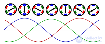
Rotating magnetic field in a three-phase single-pole synchronous motor. The direction of the field is shown by the black arrow.
Used in synchronous and asynchronous machines.
The phase difference for two-phase systems (two perpendicularly oriented electromagnets) in single-pole machines must be 90°, and for three-phase systems (three electromagnets directed in one plane at 120° to one another) 120°.
In synchronous AC generators the rotor is either a permanent magnet or an electromagnet fed by direct current — the excitation current. The rotating magnetic field in such machines induces an EMF in the stator windings, and if the machine is single-pole, the EMF frequency equals the rotor's rotational frequency.
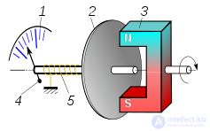
Diagram of a tachometer, whose operating principle is based on the entrainment of a non-ferromagnetic metal disc by eddy currents produced by a rotating magnetic field. 1 — scale; 2 — non-ferromagnetic metal disc; 3 — rotating permanent magnet; 4 — pointer; 5 — spring.
In tachometers, a rotating permanent magnet entrains a non-ferromagnetic metal disc whose shaft is fitted with a spring that creates a counteracting torque.
Electricity meters, for example household meters, operate on a similar principle – the entrainment of a conductive non-ferromagnetic disc by a rotating magnetic field created by the current and voltage windings.
A rotating magnetic field is also used in laboratory liquid stirrers.

Comments