
Lecture
An analytical study of the electromagnetic transient process of a synchronous machine, taking into account all factors affecting it, is an extremely complex and laborious task. To simplify it somewhat, we additionally introduce a number of assumptions:
The distribution of the magnetic flux density corresponds to a sinusoid of the fundamental frequency.
There are no losses in the magnetic system.
Full symmetry of the stator and rotor windings is maintained relative to the direct and quadrature axes.
It is assumed that there is only one equivalent winding on each of the direct and quadrature axes.
We will write the equations assuming that the rotor parameters are referred to the stator.
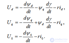
These equations are formulated according to Kirchhoff's second law and have the form:
for the flux linkages –
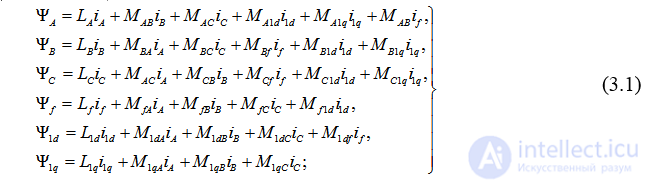
for the machine windings –
–

where k – the phase index, k =A, B, C;
f, 1d, 1f –the indices of the field winding and the damper windings respectively.
The voltages are considered known, and the currents – unknown.
The system of equations (3.1) – is linear with periodic coefficients L and M. The periodicity of the latter is due to the change in the magnetic properties of the medium caused by the rotation of the rotor. The number of distinct M values is half that used in the system, since according to the reciprocity principle 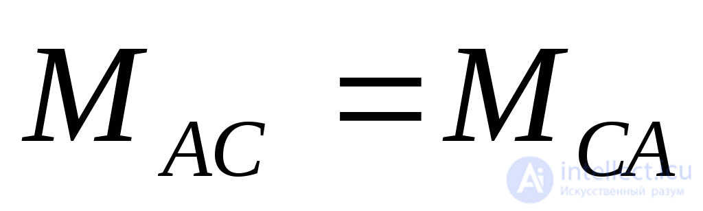 and so on.
At present there are no methods for the analytical solution of a system of differential equations of this kind. Therefore the main approach to solving engineering problems related to studying transient processes in rotating electrical machines should be considered the application of numerical methods for integrating systems of ordinary differential equations. This approach requires the use of a computer and has advantages in accuracy and simplicity of calculation, but does not give physical insight into the processes. This shortcoming is overcome by using analytical solutions, which are possible only for differential equations with constant coefficients.
A feature of the given system – the periodicity of the coefficients, caused by the rotation of the rotor – is eliminated if the system of equations is written in a coordinate system rigidly linked to the rotor. As the latter, it is convenient to choose the rotor's axes of symmetry. The transition from the A, B, C coordinate system to the d, q, o system is performed as follows:

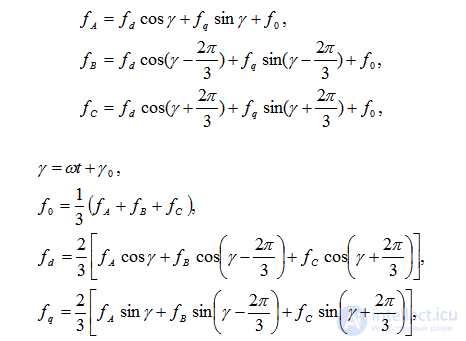
where 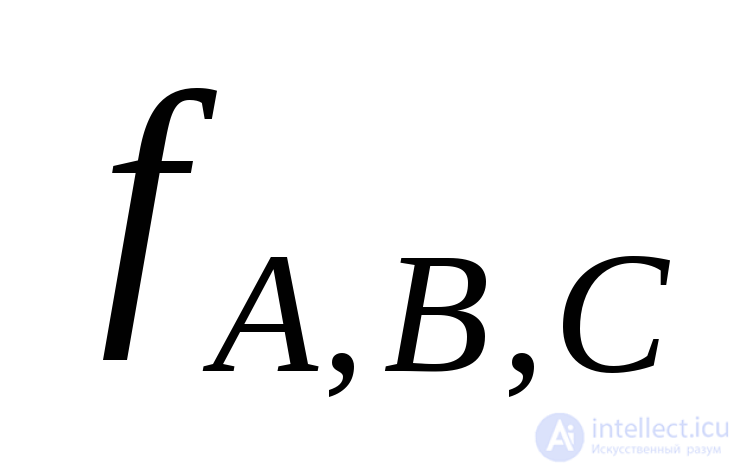 – a regime parameter in phase coordinates;
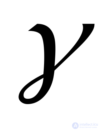 –the angle between the coordinate axis and the axis of symmetry.
For phase A in the system rigidly linked to the rotor, the equations have the form:
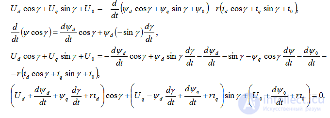
The last equation expresses Kirchhoff's second law and must be satisfied at any instant of time, i.e. for any 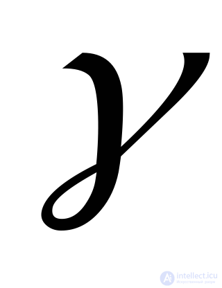 .
.
An equation of the form  for any
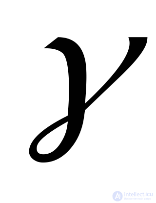 makes sense if
 i.e.
i.e.
The stator flux linkage in the direct axis has two components:
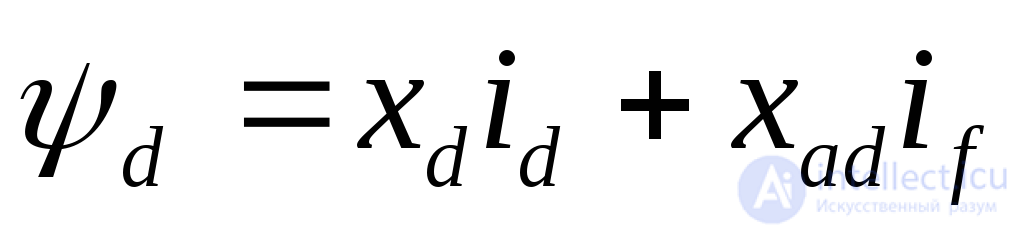 .
.
The first term – the self-inductance flux linkage, the second – the mutual-inductance flux linkage between the stator and rotor in the direct axis (in the per-unit system x=L).
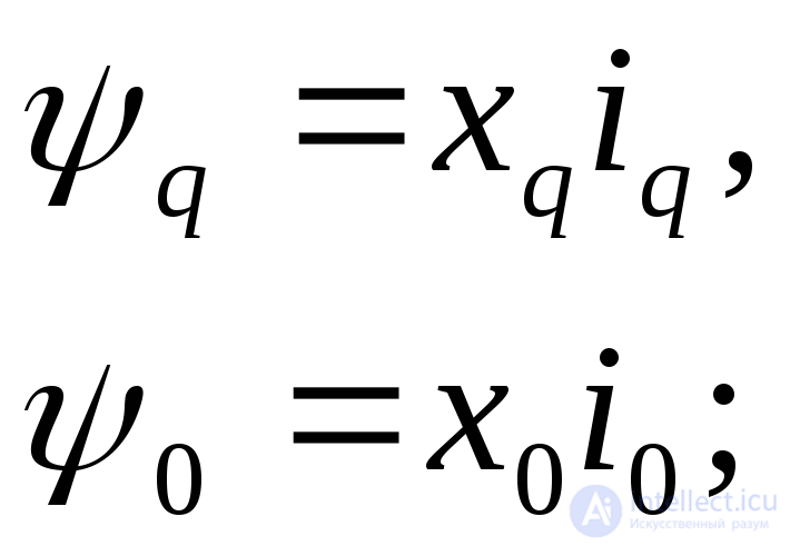
For machines without damper windings, the equations have the form:
for the flux linkages –
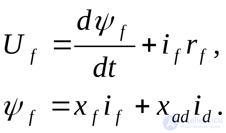
for the field winding –
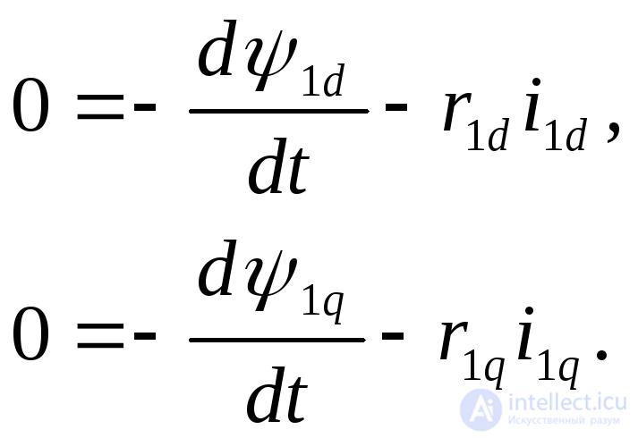
For machines with damper windings, the system of equations is supplemented by the equations
For the flux linkages the equations have the form:
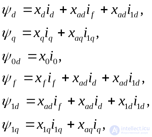
where 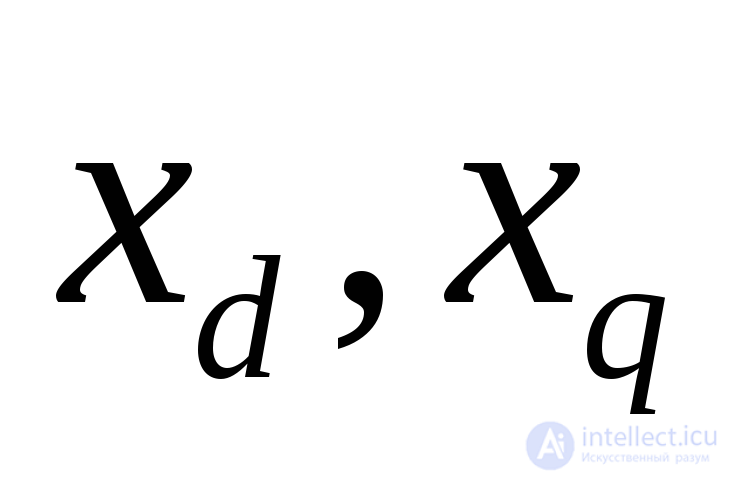 – the reactance of the stator windings in the direct and quadrature axes of symmetry respectively;
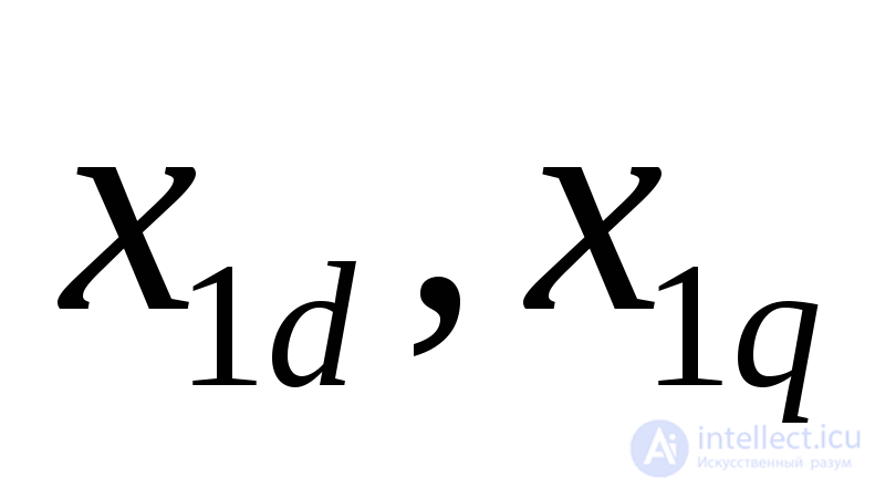 –the reactance of the rotor damper windings, located respectively in the direct and quadrature axes of symmetry;
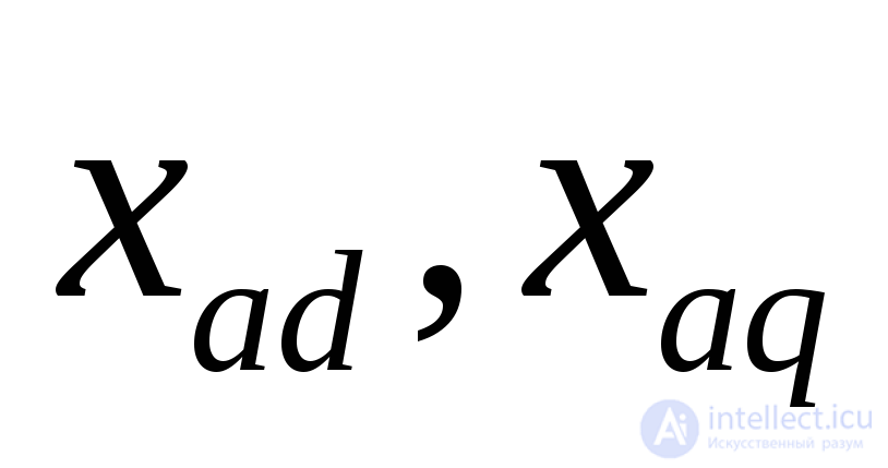 –the mutual-inductance reactance of the stator and rotor windings, located respectively in the direct and quadrature axes;
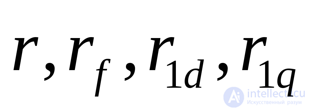 –the active resistance of the stator windings, and of the field and damper windings in the direct and quadrature axes respectively;
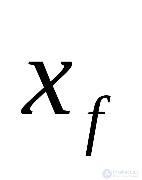 –the reactance of the field winding.
The equations given above are called the Park-Gorev equations and form the basis of the two-reaction theory known from the course "Electrical Machines".
In the voltage-balance equations for the stator windings, the terms have a fairly simple physical meaning. The first term (the derivative of the flux linkage) can be regarded as an EMF associated with the change of flux linkage (transformer EMF); the second term – as an EMF caused by the rotation of the stator windings relative to the rotor's magnetic flux (in the coordinate system rigidly linked to the rotor).
The Park-Gorev equations are characterized as linear, with constant coefficients that do not depend on the rotor position. Therefore analytical solutions are possible for them, with subsequent quantitative and qualitative analysis.
The most convenient method for solving the Park-Gorev equations is the operator method, based on the Laplace transform, which allows the operations of integration and differentiation to be replaced by algebraic ones. The structure of the operator equations exactly matches the original differential equations if the initial energy stored in the machine was zero. According to the accepted assumptions about the linearity of the system, the superposition principle can be used, i.e. the transient process with zero initial conditions can be regarded as the sum of processes: a steady-state one, which determines the nonzero initial conditions, and the transient proper, developing from zero initial conditions. For a machine with damper windings, the latter can be characterized by the Park-Gorev operator equations:
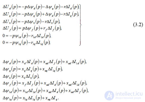
When writing these equations it is taken that 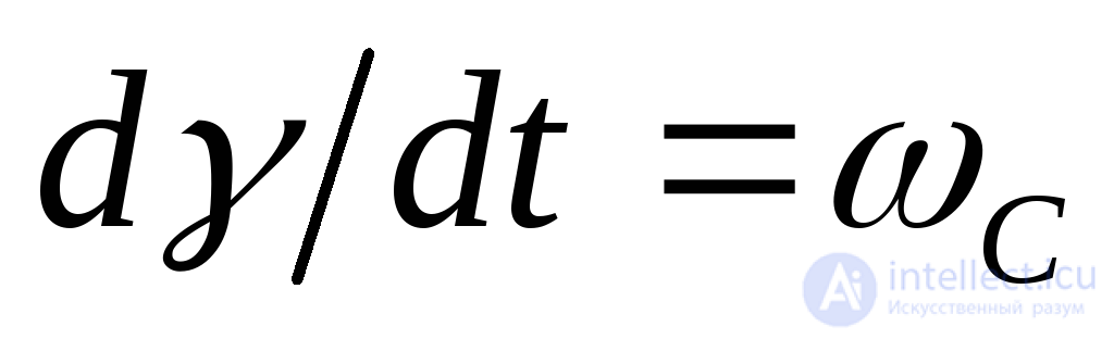 (in per-unit values
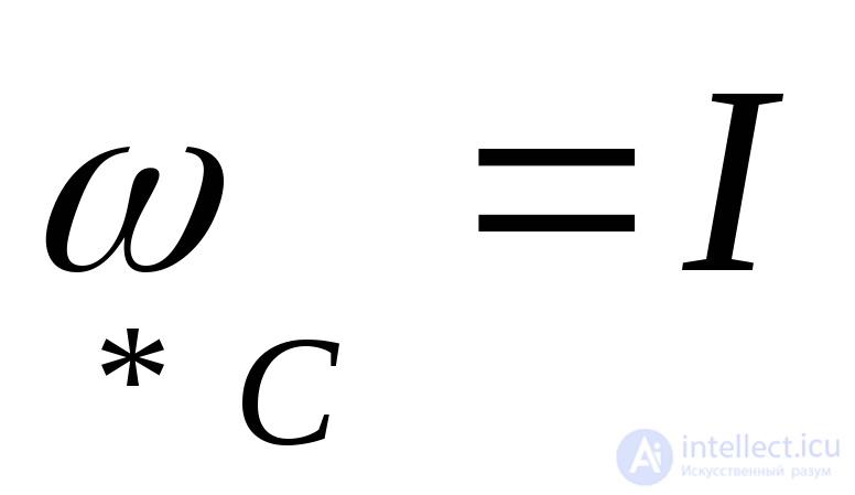 ). The symbol
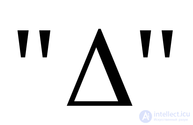 means that the corresponding regime parameters correspond only to zero initial conditions.
+Consideration of practical problems on the basis of the equations given requires the preliminary solution of a number of questions that also have independent significance. This is above all the estimation of the value of 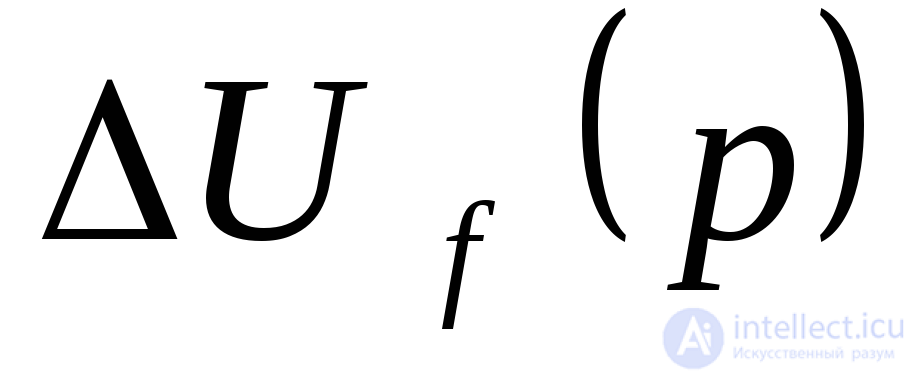 and the construction of the dynamic characteristics of the machine.
By analogy with the operator impedance 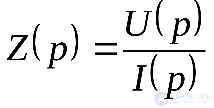 the operator reactance
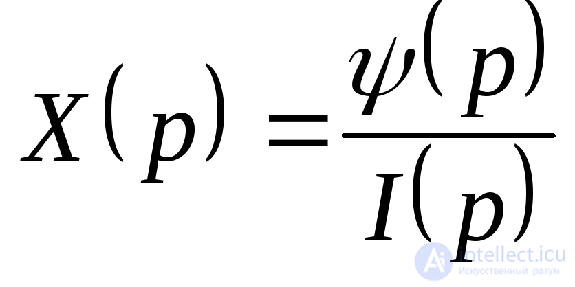 is a function relating the images of the flux linkage and the current.
The operator reactances of a machine without damper windings are determined on the basis of the equations:
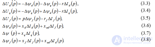
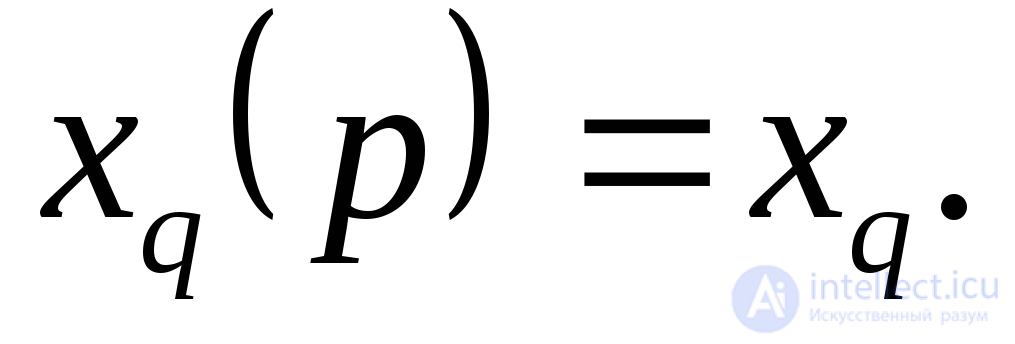
From equation (3.7) the operator reactance of the quadrature axis can be expressed:
The operator reactance in the direct axis is found using equations (3.5) and (3.6):
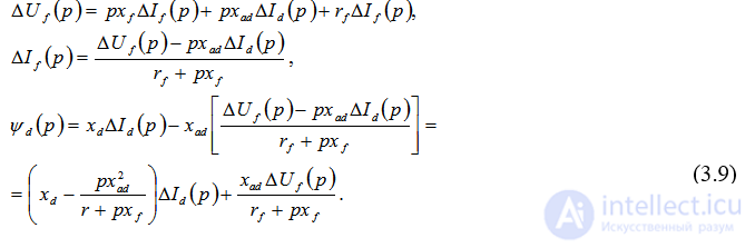
The second term of equation (3.9) does not depend on the parameter 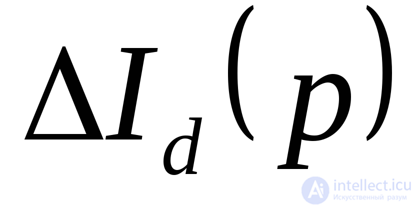 and is determined only by the properties of the excitation control system. Therefore the operator reactance in the direct axis
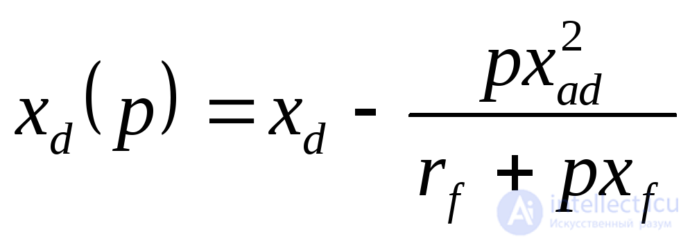 .
.
The circuit interpretation of the reactance 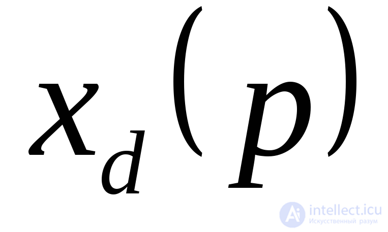 will be more illustrative if a number of transformations are carried out. Taking into account that the synchronous reactance of the stator in the direct axis has two components: the leakage reactance and the mutual-inductance reactance
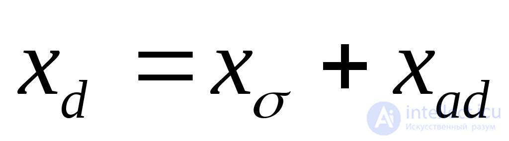 (for the field winding
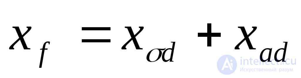 ), we obtain
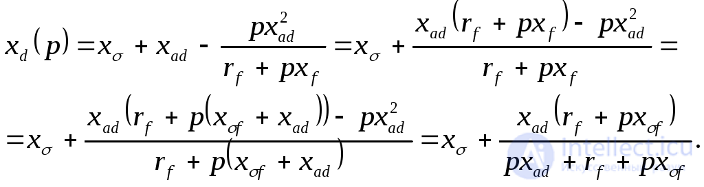 (3.10)
The second term represents the equivalent resistance of two parallel branches 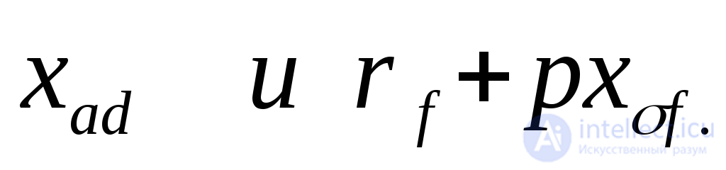 .
.
Similarly, the operator reactances of a machine with damper windings can be determined. The equivalent circuits corresponding to these reactances are shown in Fig. 3.1.
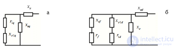
Fig. 3.1. Equivalent circuits defining the operator reactances for a machine with damper windings:
a - in the direct axis; b - in the quadrature axis.

Comments