
Lecture
When determining phase quantities beyond a transformer, it must be kept in mind that currents and voltages, on passing through a transformer, change not only in magnitude but also in phase, depending on the connection of its windings.
If the numbers of turns of the phase windings are respectively equal to ωY and ω∆, then the linear transformation ratio is
k = √3 ωY / ω∆ .
Let us consider the most commonly encountered transformer circuit with winding connection
Y0 / Δ - 11
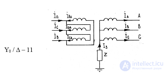
Fig.6.9.Winding connection of a transformer according to the Y/ Δ scheme
For given phase currents İA, İB and İC, in accordance with the positive directions adopted in Fig. 6.8, the currents in the line conductors beyond the delta
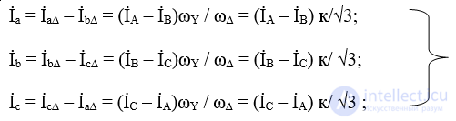 6.9
6.9
Expressing the currents in terms of their symmetrical components, we have, for example, for the current İa:
İa = (İA1 + İA2 + İ0 – a2 İA1 - a İA2 – İ0) * k /√3 =
= [(1 – a2) * İA1 + (1 – a) * İA2] * k / √3 = (6.10)
= (İA1*e j 30º + İA2*e -j 30º) * k,
from which it is seen that the line currents beyond the delta contain no zero-sequence components.
Similarly, the voltages can be found:
Ủa = (ỦA1*e j 30º + ỦA2*e -j 30º)/k. (6.11)
The structure of (6.10) and (6.11) shows that, on passing from the star side to the delta side of a transformer whose windings are connected according to group Y / Δ -11, the positive-sequence vectors are rotated by 30º in the direction of positive vector rotation, while the negative-sequence vectors are rotated by 30º in the opposite direction (Fig.6.9).
The simplest relationships are obtained for a transformer with a group-12 connection, since in this case there are no angular displacements of currents and voltages at all. But when a Y/Y connection is used, the transformed zero-sequence components must be taken into account.
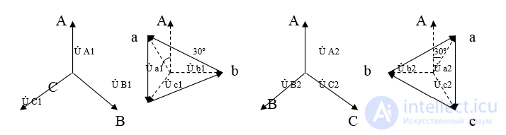
Fig. 6.10. Shift of the positive- and negative-sequence voltage vectors  for a transformer with windings connected according to the Y / Δ - 11 scheme

Comments