
Lecture
Once all elements of the circuit have been represented by parameters describing their properties at the initial instant of the transient process, calculating the initial subtransient current presents no difficulty if the corresponding axes of the machines under consideration coincide. In practice, to simplify the calculations it is often assumed that
 .
.
This makes it possible to avoid resolving these quantities along the rotor's axes of symmetry.
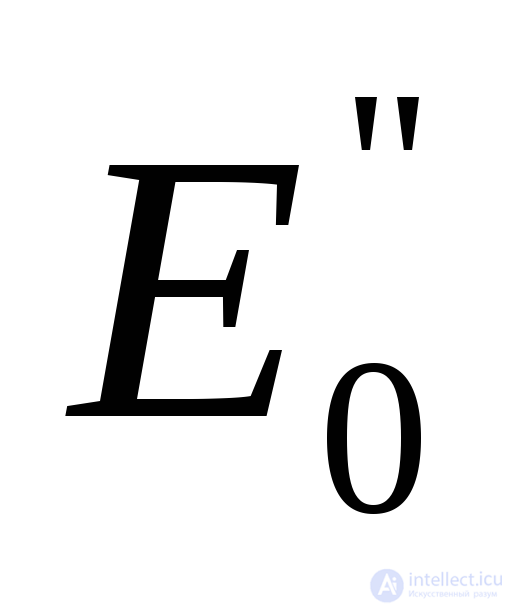
To calculate the initial subtransient current, an equivalent circuit must be set up in which synchronous generators, synchronous motors and synchronous compensators, as well as induction motors and the generalized load, are represented as  and
and . The EMF of generators and motors can be determined from the formula
 (5.1)
(5.1)
,
where 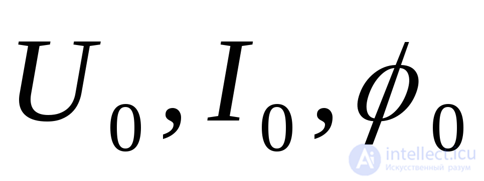 - are, respectively, the voltage at the machine terminals, the current, and the phase angle in the initial operating condition.
In formula (5.1), the sign (+) applies to synchronous generators, compensators, and synchronous motors operating overexcited, and the sign (–) applies to synchronous machines operating underexcited, and to induction motors.
In practical calculations of the initial instant of the transient process, only motors that may have a significant influence are taken into account. It is advisable to account for all other motors in the form of generalized loads, which at the initial instant can be characterized by subtransient reactances and EMFs expressed in per-unit values at the full working power of the load and the average rated voltage of the same voltage level to which it is connected: 

Motor starting can essentially be regarded as the occurrence of a short circuit behind the reactance 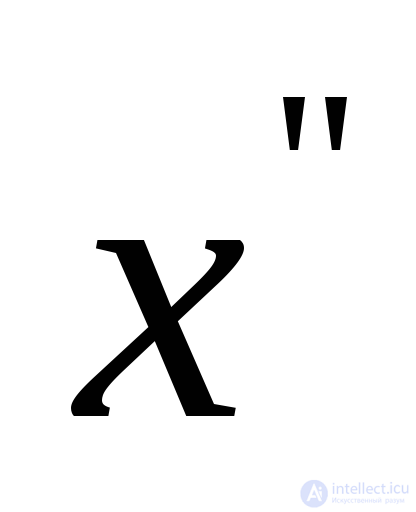 of the given motor. The per-unit reactance of an induction motor is determined as
 /
/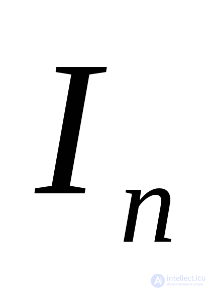 , where
 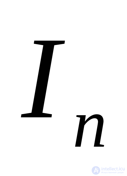 - is the motor's starting current in per-unit values.
In the absence of the necessary data, and in all approximate calculations, the average values 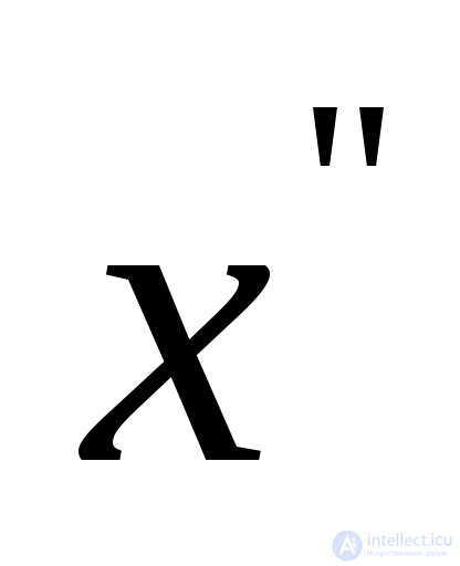 and
and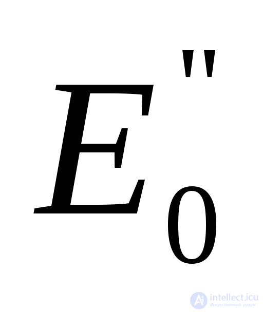 given in Table 5.1 can be used.
Table 5.1. Average values of  in per-unit values under rated conditions
|
Element name |
|
|
|
Turbogenerator with rated power up to 100 MW Same, rated power 100 – 500 MW Hydrogenerator with damper windings Same, without damper windings Synchronous motor Synchronous compensator Induction motor Generalized load |
0,125 0,2
0,2 0,27 0,2 0,2 0,2 0,35 |
1,08 1,13
1,13 1,18 1,10 1,20 0,9 0,85 |
For a given initial operating condition, the well-known superposition method can be used, according to which the current at the initial instant of the transient process can be found by superimposing the actual fault current on the initial one. The actual current is obtained as the result of superimposing a number of fictitious currents, each of which is determined by the action of one or several EMFs, with all other elements of the circuit remaining connected.
The influence of the load at the initial instant of a three-phase short circuit depends on the residual voltage at its point of connection. The farther the power source (power plant, power-system substation) is from the fault location, and the closer the load is to that point, the stronger its relative role in increasing the short-circuit current. Usually only those loads and individual motors that are directly connected to the fault location, or are at a small electrical distance from it, are taken into account.
The surge (peak) current, determined for the most severe conditions, accounts only for the decay of the aperiodic component of the current:
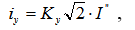 ,
,
where  - is the surge (peak) factor.
For large synchronous and induction motors 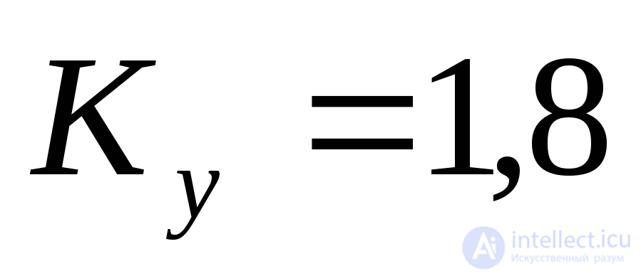 , and for generalized loads and small motors
 .
.
When motors are accounted for separately, the surge current at the fault location
 ,
,
where 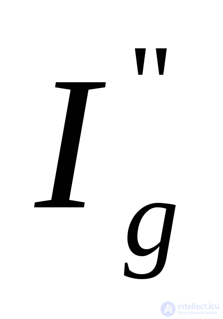 - is the initial subtransient current of the motor;
 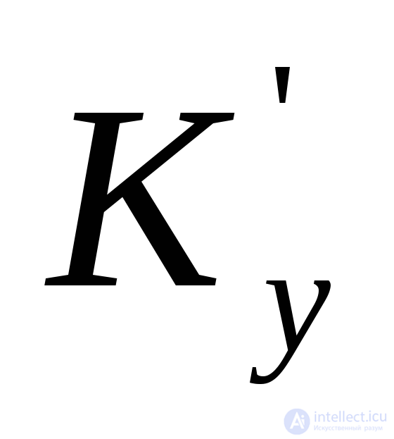 – is the surge factor for this motor.
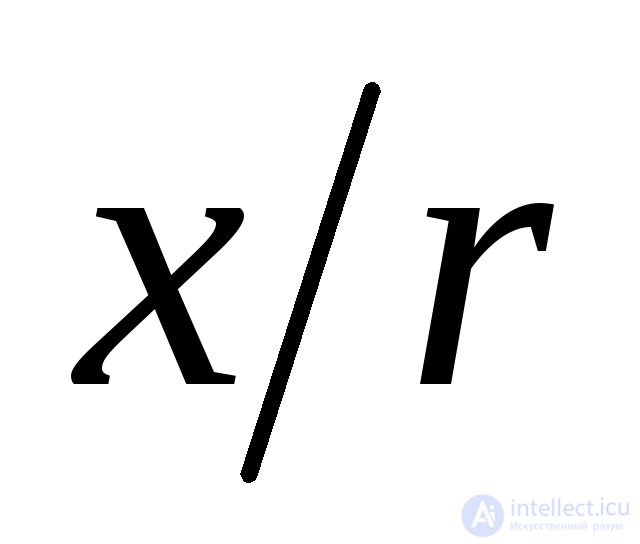
The surge factor, as shown in Section 1, depends on the time constant 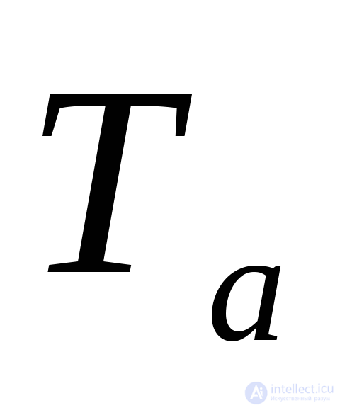 or on the ratio
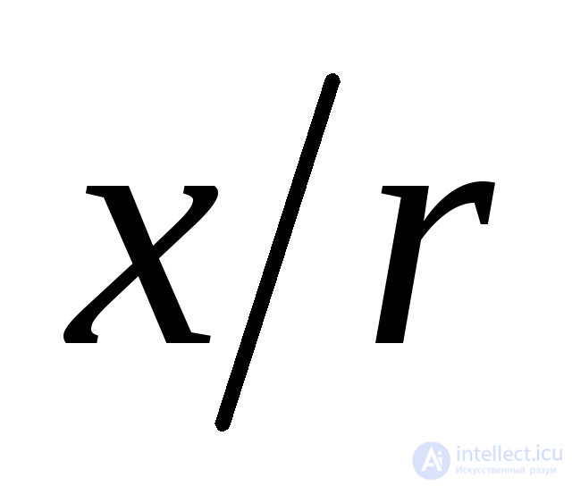 .
.
If the necessary data on the resistance values of individual power-system elements are unavailable, one can be guided by the ranges of the ratio 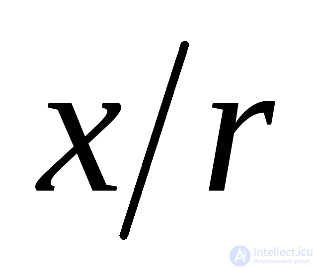 given in Table 5.2.
Table 5.2. Values of 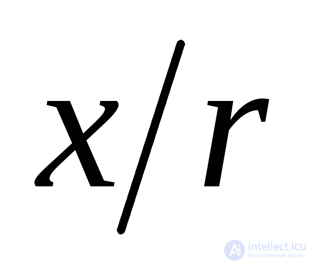 for power-system elements
|
Circuit elements |
|
|
Turbogenerators with rated power 20…100 MW 00…500 MW Hydrogenerators without damper windings with damper windings Transformers with rated power 5…30 MVA 60…500 MVA Current-limiting reactors
Overhead lines Cable lines System (infinite-power bus) |
15…85 100…140 60…90 40…60 7…17 20…50 15…17 40…60
2…8 0,2…0,8 50
|
In rough calculations, the equivalent time constants are not computed, and the surge factor is instead determined as an average value depending on the fault location (Table 5.3).
Table 5.3. Averaged surge factors
|
Fault location |
|
|
|
- with transformers of 30…100 MVA per unit. - with transformers larger than 100 MVA per unit.
|
40…80
20…60 20…60
15…30 20…40
|
[[b8458]]
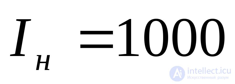 A
A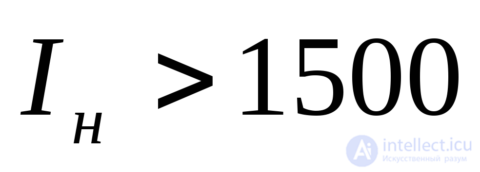 A
A


Comments