
Lecture
The zero-sequence current of an overhead line flows through the ground and through grounded circuits located parallel to the given line (protective shield wires, rail tracks running alongside the line, etc.).
The main difficulty is the reliable determination of the zero-sequence impedance of an overhead line, taking into account the distribution of current in the ground. A sufficiently complete and rigorous solution for the distribution of current in the ground was carried out by Carson. Replacing the overhead three-phase line with an equivalent circuit of three two-wire "conductor – ground" lines, Carson showed that the inductance of such a line can be determined as the inductance of an equivalent two-wire line with a spacing between conductors of D3. This distance is called the depth of current return through the ground. At f = 50 Hz, with an average ground resistivity of 10-4 1/Ohm·cm ; D3 ≈ 1000 m.
In symmetrical three-phase positive- and negative-sequence systems, the mutual inductance between the phase taken as the reference phase and the neighboring phases reduces the line's reactance. In the zero-sequence system, by contrast, mutual inductance leads to an increase in the phase's magnetic flux. Therefore, the zero-sequence impedance is much greater than the positive-sequence impedance (x0 > x1 = x2).
When a well-conducting grounded shield wire is present on the line, the impedance x0 is reduced due to the mutual inductance between the shield wire and the conductor, since the current in the shield wire is directed opposite to the currents in the conductors (Fig. 6.4). The influence of a steel shield wire is smaller because of the high resistivity of steel. The zero-sequence impedance of a double-circuit overhead line is greater the more parallel circuits the line has, since, with zero-sequence currents flowing in the same direction, the mutual inductance of the parallel circuits increases their total impedance.
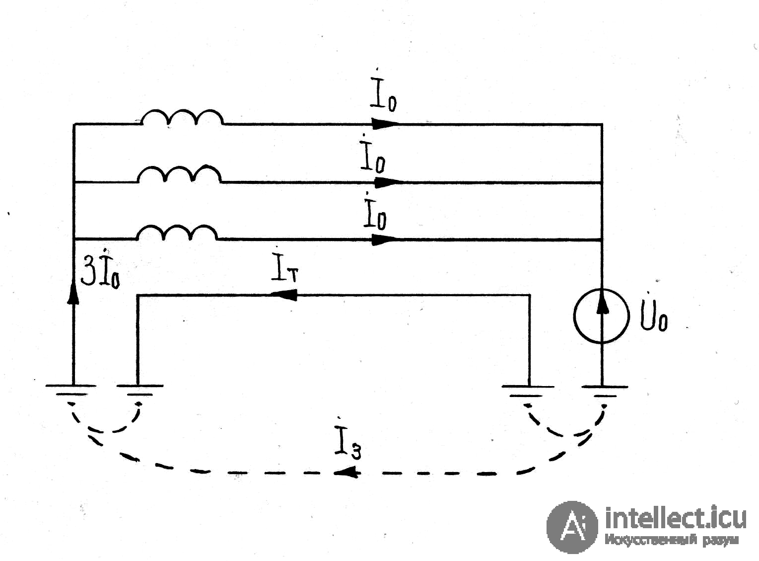
Fig. 6.5. Single-circuit overhead line with a grounded shield wire
The calculation expression for determining the zero-sequence impedance of a single-circuit line without a shield wire has the form
x0 = 0.435 lg D3/Ra v, (6.6)
where D3 – the depth of current return through the ground, m;
Ra v – the geometric mean radius of the three conductors, m.
A single-circuit overhead line with one shield wire is determined by an analogous formula that accounts for the shield wire :
x0s = x0 – x0 c-s – x0 s, (6.7)
where x0 c-s – the mutual-inductance impedance between the line conductors and the shield wire,
x0 s – the zero-sequence impedance of the shield wire.
For approximate practical calculations, average values of the ratios between the reactances x0 and x1 are given in Table 6.1.
Table 6.1 Average values of the ratios between x0 and x1 for overhead transmission lines
|
Line characteristic |
Ratio x0/x1 |
|
Single-circuit line without shield wires |
3.5 |
|
Same, with steel shield wires |
3.0 |
|
Same, with well-conducting shield wires |
2.0 |
|
Double-circuit line without shield wires |
5.5 |
|
Same, with steel shield wires |
4.7 |
|
Same, with well-conducting shield wires |
3.0 |
The zero-sequence impedance of cable lines depends on the type of cable, its laying method, the parameters of the cable sheaths and the nature of their grounding, and the parameters of the grounding electrodes.
In approximate calculations for three-core cables, it is usually taken that
x0 = (3.5…4.6) x1, ro ≈ 10 r1. (6.8)
+When calculating networks with isolated neutrals, it is also necessary to know the capacitive zero-sequence reactance of the cables. This data is provided by the manufacturer or determined by calculation or experimentally.
[[b8464]]

Comments