
Lecture
Transients in a circuit with a single energy-storage element and an arbitrary number of resistors
As noted in the previous lecture, a linear circuit is governed by a single, unified transient process. Therefore, in the circuits under consideration with a single energy-storage element (an inductor or a capacitor) – first-order circuits – the time constant is the same for all free components of the branch voltages and currents whose parameters enter the characteristic equation.
The general approach to calculating transients in such circuits is based on applying the active two-terminal network theorem: the branch containing the storage element is separated from the circuit, and the remaining part of the circuit is treated as an active two-terminal network A (equivalent generator) (see Fig.1, a) with the equivalent circuit shown in Fig. 1,b.
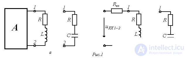
It is quite obvious that here the time constant for circuits with an inductive element is determined as:
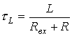 ,
,
and for a capacitive one, as:
 ,
,
where  is the input resistance of the circuit with respect to terminals 1-2 to which the branch containing the energy-storage element is connected.
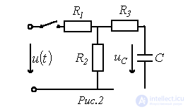
For example, for the voltage across the capacitor in the circuit of Fig. 2, we can write
 ,
,
where, in accordance with the above,
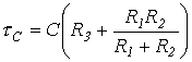 .
.
Transients when a series
R-L-C circuit is connected to a voltage source
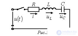
Let us consider two cases:
a)  ;
;
b)  .
.
According to the classical-method procedure for calculating transients described in the previous lecture, for the voltage across the capacitor in the circuit of Fig. 3 we can write
 . . |
(1) |
Then, for the first case, the forced component of this voltage is
 . . |
(2) |
The characteristic equation of the circuit
 ,
,
solving which, we obtain
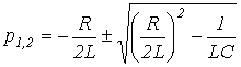
Depending on the relationship between the circuit parameters, three types of roots are possible, and accordingly three variants of the expression for the free component:
1.  or
or 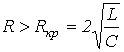 , where
  is the critical resistance of the loop, below which the free process is oscillatory in nature.
In this case
 . . |
(3) |
2.  - the limiting case of the aperiodic mode.
In this case  and
and
 . . |
(4) |
3.  - a periodic (oscillatory) character of the transient.
In this case  and
and
 , , |
(5) |
where  is the damping coefficient;
 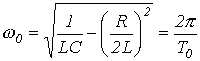 is the angular frequency of natural oscillations;
  is the period of natural oscillations.
For the aperiodic character of the transient, after substituting (2) and (3) into relation (1), we can write
 .
.
To find the integration constants, taking into account that in the general case  and, in accordance with the first commutation law,
 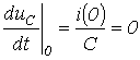 , we write two equations for t=0:
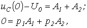
solving which, we obtain
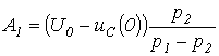 ;
; 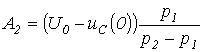 .
.
Thus,
 .
.
Then the current in the circuit

and the voltage across the inductor
 .
.
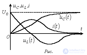
Fig. 4 shows the qualitative curves of  ,
,  and
and  , corresponding to the aperiodic transient at
  .
.
For the critical mode, based on (2) and (4), we can write
 .
.
At 
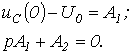
Thus

and

For the oscillatory transient, in accordance with (2) and (5), we have
 .
.
To find the integration constants, let us write 
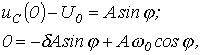
from which  and
and  .
.
Then
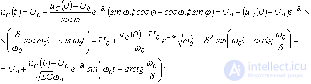
 .
.
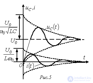
Fig. 5 shows the qualitative curves of  and
and  , corresponding to the oscillatory transient at
  .
.
When an R-L-C circuit is connected to a sinusoidal voltage source, the phasor method should be used to find the forced components of the circuit current and the capacitor voltage, according to which
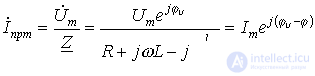
and
 ,
,
where  ;
;  ;
;  .
.
Thus,
 and
and  .
.
Here too, three modes are possible:
1.  ; ; |
2.  |
3.  |
 |
 |
 |
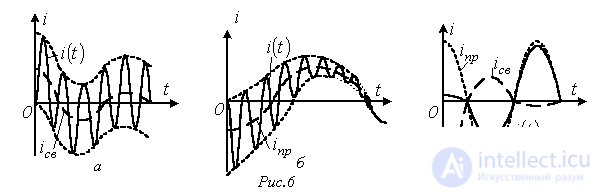
The third mode is of greatest interest, being associated with the appearance of natural oscillations at a frequency of  during the transient. Depending on the relationship between the frequency of the natural oscillations and that of the source voltage, three characteristic variants are possible: 1 -
  ; 2 -
; 2 -  ; 3 -
; 3 -  , - which are shown in Fig. 6,a…6,c respectively.
References
Review questions
Answer: charge.
Answer: L=0.225 H.
Answer:  .
.
Answer:  .
.
 , C=10 µF. What must the inductance L of the coil installed in place of the capacitor be equal to so that the time constant does not change?
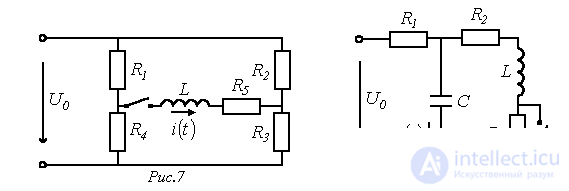
 through the inductor in the circuit of Fig. 7, if
  ;
;  ;
;  ;
;  ;
;  .
. in the branch with the capacitor in the circuit of Fig. 8, if
  ;
;  ;
;  ;
;  .
.
Comments