
Lecture
The choice of one or another method for calculating an electric circuit is ultimately determined by the objective of the problem being solved. Therefore, the analysis of a linear circuit does not necessarily have to be carried out using such general calculation methods as the mesh-current method or the node-potential method. Below we consider methods based on the properties of linear electric circuits, which, for certain problem formulations, allow them to be solved more economically.
This method is valid only for linear electric circuits and is particularly effective when it is necessary to calculate currents for various values of the source EMFs and currents while the resistances of the circuit remain unchanged.
This method is based on the superposition principle, which is formulated as follows: the current in the k-th branch of a linear electric circuit equals the algebraic sum of the currents caused by each of the sources acting separately.
Analytically, the superposition principle for a circuit containing n EMF sources and m current sources is expressed by the relation
 . . |
(1) |
Here  is the complex input admittance of the k-th branch, numerically equal to the ratio of the current to the EMF in this branch when the EMFs in the other branches are equal to zero;
  is the complex mutual admittance of the k-th and i-th branches, numerically equal to the ratio of the current in the k-th branch to the EMF in the i-th branch when the EMFs in the other branches are equal to zero.
The input and mutual admittances can be determined experimentally or analytically, using their stated physical interpretation, whereby  , which follows directly from the reciprocity property (see below).
The current transfer coefficients  are defined similarly; unlike admittances, they are dimensionless quantities.
The superposition principle can be proved on the basis of the mesh-current method.
If the system of equations set up by the mesh-current method is solved for any mesh current, for example  , we obtain
 , , |
(2) |
where 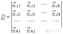 is the determinant of the system of equations set up by the mesh-current method;
  is the cofactor of the determinant
  .
.
Each of the EMFs in (2) is an algebraic sum of the EMFs in the branches of the i-th mesh. If we now replace all the mesh EMFs in (2) with the algebraic sums of the EMFs in the corresponding branches, then, after grouping terms, we obtain an expression for the mesh current  as an algebraic sum of the component currents caused by each of the branch EMFs acting separately. Since the system of independent meshes can always be chosen so that the given h-th branch belongs to only one
  -th mesh, i.e. the mesh current
  will equal the actual current
  of the h-th branch, the superposition principle is valid for the currents
  of any branches, and hence the validity of the superposition principle is proved.
Thus, when determining branch currents using the superposition method, one should leave, in turn, a single source in the circuit, replacing the others with their internal resistances, and calculate the component currents in these circuits. The results obtained for the corresponding branches are then summed - these are the required currents in the branches of the original circuit.
As an example of using the superposition method, let us determine the current in the second branch of the circuit in Fig. 1,a.
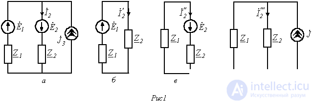
Assuming the sources in the circuit of Fig. 1,a to be ideal, and taking into account that an ideal EMF source has zero internal resistance while an ideal current source has infinite internal resistance, in accordance with the superposition method we arrive at the computational circuits of Fig. 1,b…1,d.
In these circuits
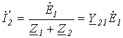 ;
; 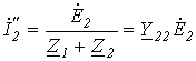 ;
; 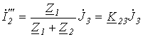 ,
,
where  ;
;  ;
;  .
.
Thus,
 .
.
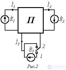
As another example of using the method, let us determine the mutual conductances  and
and  in the circuit of Fig. 2, if, when the switch is moved to position 1, the currents in the first and second branches are respectively equal to
  and
and  , while when moved to position 2 they are
  and
and  .
.
Considering that the structure of a passive two-port network contains no energy sources, on the basis of the superposition principle, for the switch in position “1” we can write
 ; ; |
(3) |
 . . |
(4) |
With the switch in position “2” we have
 ; ; |
(5) |
 .. .. |
(6) |
Then, subtracting relation (5) from equation (3), and (6) from (4), we obtain
 ;
;
 ,
,
from which the required conductances are
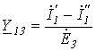 ;
; 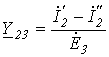 .
.
The reciprocity principle is based on the reciprocity theorem, which we state without proof: for a linear circuit, the current  in the k-th branch caused by the only EMF source in the circuit
  , located in the i-th branch,

will be equal to the current  in the i-th branch, caused by an EMF
  , numerically equal to the EMF
  , located in the k-th branch,
 .
.
From this, in particular, follows the relation noted above  .
.
In other words, the reciprocity principle, based on the reciprocity theorem, states: if an EMF  , acting in some branch of a circuit containing no other sources, causes a current
  in another branch (see Fig. 3,a), then the same EMF
  transferred to that branch will cause the same current
  in the first branch (see Fig. 3,b).
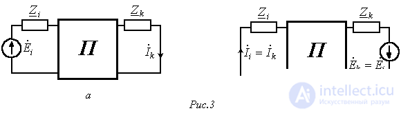
As an example of applying this principle, consider the circuit in Fig. 4,a, in which it is required to determine the current  caused by the EMF source
  .
.
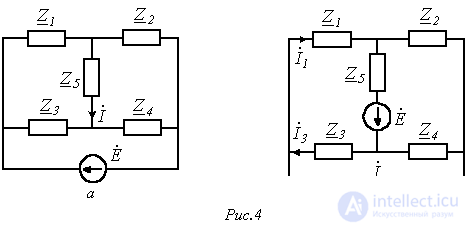
Transferring the EMF source  into the diagonal of the bridge, where the current is to be found, transforms the original circuit into a series-parallel circuit as in Fig. 4,b. In this circuit
 , , |
(7) |
where  .
.
In accordance with the reciprocity principle, the current  in the circuit of Fig. 4,a is equal to the current determined by relation (7)
When the EMF (current) of one of the sources, or the resistance in some branch, changes in a linear electric circuit, the currents in any pair of branches m and n will be related to each other by
 ,
, |
(8) |
where A and B – are certain constants, generally complex.
Indeed, in accordance with (1), for a change in the EMF  in the k-th branch, the current in the m-th branch can be written as
 |
(9) |
and for the current in the n-th branch –
 . . |
(10) |
Here  and
and  are the components of the currents in the m-th and n-th branches, respectively, due to all the other sources except
  .
.
Multiplying the left and right sides of (10) by  , and subtracting the resulting relation from equation (9), we obtain
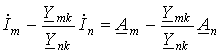 . . |
(11) |
Denoting in (11)  and
and 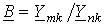 , we arrive at relation (8).
Note that, in accordance with Ohm's law, an analogous relation for the voltages in a linear circuit follows from equation (8).
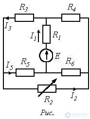
As an example, let us find the analytical relationship between the currents  and
and  in the circuit with a variable resistor in Fig. 5, where
  ;
;  ;
;  .
.
The coefficients A and B can be calculated by considering any two operating modes of the circuit corresponding to two arbitrary values of  .
.
Choosing as these values  and
and  , for the first case (
  ) we write
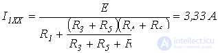 .
.
Thus,  .
.
At  (short-circuit mode)
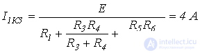 ,
,
from which
 .
.
On the basis of (8)
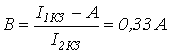 .
.
Thus,
 .
.
The compensation principle is based on the compensation theorem, which states: in any electric circuit, without changing the currents in its branches, the resistance in an arbitrary branch can be replaced by a source with an EMF numerically equal to the voltage drop across that resistance and acting against the current in that branch.
To prove the theorem, let us isolate from the circuit an arbitrary branch with resistance  , carrying a current
  , while the rest of the circuit is denoted conventionally as an active one-port network A (see Fig. 6,a).
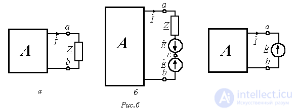
When two identical EMF sources with  acting against each other are inserted into the branch with
  (Fig. 6,b), the operating mode of the circuit does not change. For this circuit
 . . |
(12) |
Equality (12) allows points a and c to be galvanically connected, i.e. to move to the circuit in Fig. 6,c. Thus, the theorem is proved.
In conclusion, it should be noted that, similarly, to simplify calculations, any branch with a known current  can be replaced by a current source
  .
.
References
Review questions and problems
Answer:  , where
  ;
;  .
.
Answer:  ;
;  .
.
 . Determine the currents in the remaining branches of the circuit using the linear relation, the compensation principle and the superposition method.
Comments