
Lecture
The transfer of energy w along an electric circuit (for example, along a transmission line), the dissipation of energy, that is, the conversion of electromagnetic energy into heat, as well as other types of energy conversion, are characterized by the intensity with which the process takes place, that is, by how much energy is transferred along the line per unit time, or how much energy is dissipated per unit time. The intensity of energy transfer or conversion is called power p. This corresponds to the mathematical definition:
 . . |
(1) |
The expression for the instantaneous value of power in electric circuits has the form:
 . . |
(2) |
Taking the initial phase of the voltage as zero, and the phase shift between voltage and current as  , we obtain:
 . . |
(3) |
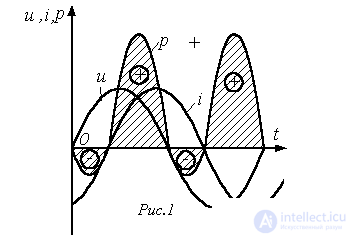
Thus, the instantaneous power has a constant component and a harmonic component, whose angular frequency is twice the angular frequency of the voltage and current.
When the instantaneous power is negative, which occurs (see Fig. 1) when u and i have opposite signs, i.e., when the directions of the voltage and current in the two-terminal network are opposite, energy is returned from the two-terminal network to the source.
This return of energy to the source occurs because energy is periodically stored in the magnetic and electric fields of the inductive and capacitive elements, respectively, that make up the two-terminal network. The energy delivered by the source to the two-terminal network during a time t equals  .
.
The average value of the instantaneous power over a period is called the active power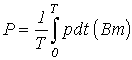 .
.
Taking into account that 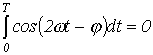 , from (3) we obtain:
 . . |
(4) |
The active power consumed by a passive two-terminal network cannot be negative (otherwise the two-terminal network would be generating energy), so  , i.e., at the input of a passive two-terminal network
  . The case P=0,
  is theoretically possible for a two-terminal network that has no active resistance and contains only ideal inductive and capacitive elements.
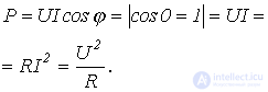
1. Resistor (ideal active resistance).
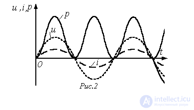
Here the voltage and current (see Fig. 2) are in phase  , so the power
  is always positive, i.e., the resistor consumes active power
2. Inductor (ideal inductance)
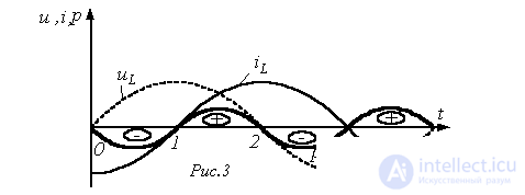
For an ideal inductance, the current lags the voltage in phase by  . Therefore, in accordance with (3), we can write
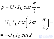 .
.
Section 1-2: the energy  stored in the magnetic field of the coil increases.
Section 2-3: the energy of the magnetic field decreases, returning to the source.
3. Capacitor (ideal capacitance)
The processes for an ideal capacitance are similar in nature. Here  . Therefore, it follows from (3) that
  . Thus, active power is not consumed in the inductor or the capacitor (P=0), since no irreversible conversion of energy into other forms of energy takes place in them. Here only a circulation of energy occurs: electrical energy is stored in the magnetic field of the coil or in the electric field of the capacitor during a quarter of the period, and during the next quarter of the period the energy is returned to the network again. For this reason the inductor and the capacitor are called reactive elements, and their reactances XL and XC , unlike the active resistance R of a resistor, – are reactive.
The intensity of the energy exchange is customarily characterized by the largest value of the rate at which energy enters the magnetic field of the coil or the electric field of the capacitor, which is called the reactive power.
In the general case, the expression for the reactive power has the form:
 |
(5) |
It is positive for a lagging current (inductive load-  ) and negative for a leading current (capacitive load-
  ). The unit of power used to measure reactive power is called the volt-ampere reactive (VAr).
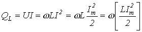
In particular, for an inductor we have:
 , since
  .
.
 .
.
From the last expression it can be seen that the reactive power of an ideal inductor is proportional to the frequency and to the maximum energy stored in the coil. A similar expression can be obtained for an ideal capacitor:
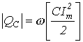 .
.
Apparent Power
In addition to the concepts of active and reactive power, the concept of apparent power is widely used in electrical engineering:
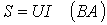 . . |
(6) |
The active, reactive, and apparent powers are related by the following expression:
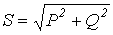 . . |
(7) |
The ratio of the active power to the apparent power is called the power factor. From the relations given above it can be seen that the power factor  equals the cosine of the phase angle between the current and the voltage. Thus,
 . . |
(8) |
Complex Power
The active, reactive, and apparent powers can be determined using the complex representations (phasors) of the voltage and current. Let  , and
, and  . Then the complex apparent power is:
 , , |
(9) |
where  - is the complex conjugate of the complex
  .
.
 .
.
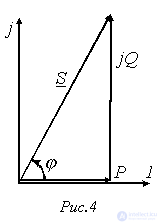
A power triangle can be associated with the complex power (see Fig. 4). Fig. 4 corresponds to  (an active-inductive load), for which we have:
Use of Static Capacitors to Improve cos
As already noted, the reactive power  circulates between the source and the load. Reactive current, without doing any useful work, leads to additional losses in power equipment and, consequently, to an oversizing of its rated power. In this connection, the desire to increase
  in power circuits is understandable.
It should be noted that the overwhelming majority of loads (electric motors, electric furnaces, and various other devices and instruments) are active-inductive in nature.
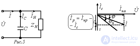
If a capacitor C is connected in parallel with such a load  (see Fig. 5), then the total current
  , as can be seen from the phasor diagram (Fig. 6), moves closer in phase to the voltage, i.e.,
  increases, while the overall magnitude of the current (and consequently the losses) decreases, the active power
  remaining constant. This is the basis for using capacitors to increase
  .
.
What capacitance C must be chosen to increase the power factor from the value  to the value
 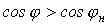 ?
?
Let us resolve  into an active
  and a reactive
 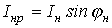 component. The current through the capacitor
  compensates part of the reactive component of the load current
  :
:
 ; ; |
(10) |
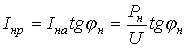 ; ; |
(11) |
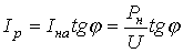 . . |
(12) |
From (11) and (12), taking (10) into account, we have
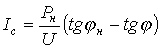 ,
,
but  , from which the capacitance required to increase
  is:
is:
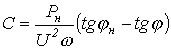 . . |
(13) |
Power Balance
The power balance is a consequence of the law of conservation of energy and can serve as a criterion for the correctness of an electric-circuit calculation.
a) Direct current
For any direct-current circuit the following relation holds:
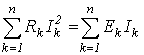 |
(14) |
This equation is the mathematical form of the power balance: the total power generated by the sources of electrical energy equals the total power consumed in the circuit.
It should be noted that in the left-hand side of (14) the terms have a “+” sign, since active power is dissipated in resistors. In the right-hand side of (14) the sum of the terms is greater than zero, but individual terms here may have a “-” sign, which indicates that the corresponding sources are operating as consumers of energy (for example, a battery being charged).
b) Alternating current.
From the law of conservation of energy it follows that the sum of all delivered active powers equals the sum of all consumed active powers, i.e.
 |
(15) |
It is proved in circuit theory (owing to the considerable length of the derivation, this proof is omitted here) that the balance also holds for reactive powers:
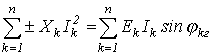 , , |
(16) |
where the “+” sign refers to inductive elements  , and the “-” sign – to capacitive elements
  .
.
Multiplying (16) by “j” and adding the result to (15), we arrive at the analytical expression of the power balance in sinusoidal-current circuits (without taking mutual inductance into account):

or
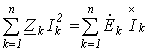 .
.
References
Review Questions and Problems
Answer: P=250 W; Q=433 VAr; S=500 VA.
Answer: R=30 Ω; XL=40 Ω.
Answer: R=10 Ω; XC=7.5 Ω.
 ?
? , and the current in it is
  . Determine the active, reactive, and apparent powers.
Comments