
Lecture
The essence of the equivalent-sinusoid method was presented in Lecture No. 35 when discussing its graphical implementation. In the analytical version of the method, the main stage of graphical construction — in particular, phasor diagrams — is absent; it is replaced by the corresponding calculations using analytical relations for the complex values of the equivalent sinusoidal quantities.
The graphical version of the equivalent-sinusoid method is characterized, primarily for relatively simple circuits, by greater visual clarity. At the same time, the analytical approach increases calculation accuracy by eliminating the errors associated with graphical construction.
Switching to equivalent sinusoids in combination with the symbolic (phasor) method makes it possible to build equivalent substitution circuits with equivalent parameters  and
and  . The difficulty of the analysis and calculation lies in the fact that the values of these parameters depend on the sought voltages, currents, and fluxes, i.e., they are not known in advance.
Switching to equivalent sinusoids corresponds to replacing the real hysteresis loops 
 or
or 
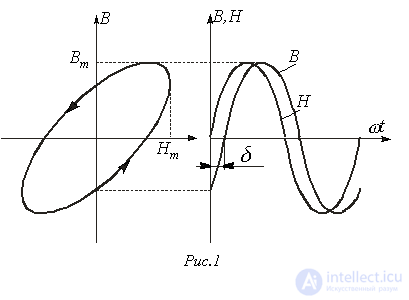
 with equivalent ellipses. Figure 1 shows the equivalent ellipse replacing the real curve
  , to which correspond parametric equations defined by sinusoidal functions
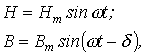
where  is the loss angle, which determines the power loss per unit volume of the ferromagnetic material over one magnetization reversal cycle
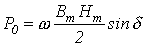 .
.
Under alternating current, losses in the core steel are determined not only by hysteresis but also by eddy currents induced by the alternating flux. Thus, the dynamic hysteresis loop is wider than the static one and differs from it in shape. Note that to reduce eddy-current losses, the core is laminated from insulated thin sheets (at a frequency of  Hz their thickness is
  mm), made of steels with special additives that reduce conductivity.
Neglecting the nonuniformity of the magnetic flux density distribution over the cross section, the eddy-current loss power is determined by the relation
 ,
,
where  is an empirical coefficient determined by the grade of steel and the sheet size; G is the mass of the core.
In turn, the hysteresis loss power is
 ,
,
where n=1.8…2.2 (often, as a first approximation, n=2 is taken);  is an empirical coefficient depending on the grade of steel.
The total losses in the steel  , besides those indicated, are also determined by additional losses
  associated with the magnetic viscosity of the material, i.e.
 .
.
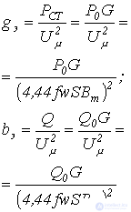
To determine the parameters of the equivalent current sinusoid — its rms value and loss angle (phase shift relative to the magnetic flux) — it is convenient to use the relation for the power loss in the steel

and the magnetizing power

where  is the voltage applied to the nonlinear inductor coil with the number of turns
  and core cross-sectional area
  ;
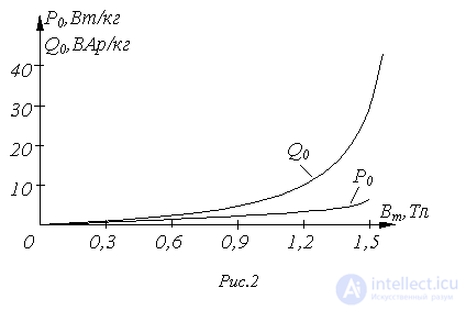
;  are, respectively, the specific (per unit mass of core) steel losses and magnetizing power. The values of
  and
and  are taken from experimental characteristics
  and
and  , which express the dependence of these quantities on the flux-density amplitude (see, for example, the curves in Fig. 2) under sinusoidal-flux-density conditions.
Switching to equivalent sinusoids and, correspondingly, to the equivalent ellipse replacing the real curve  , makes it possible to introduce the relative complex magnetic permeability
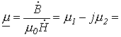
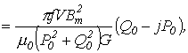
where  is the volume of the core steel of length
  and cross section
  ,
,
and the complex magnetic reluctance

which is the analog of the magnetic reluctance  in nonlinear circuits with constant magnetic fluxes.
Coil with a ferromagnetic core
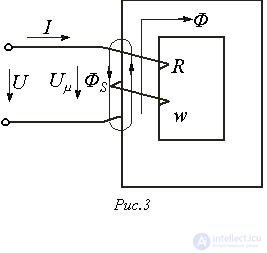
A nonlinear inductor coil is shown in Fig. 3. Here R is the active resistance of the winding with the number of turns w; Φ is the main flux closing through the core;  is the leakage flux, to which correspond the leakage inductance
  and the leakage reactance
  .
.
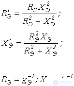
A distinction is made between the parallel and series equivalent circuits of a coil with a ferromagnetic core. These circuits, along with the corresponding relations and phasor diagrams, are given in Table 1.
Table 1. Equivalent circuits, equations, and phasor diagrams for a coil with a ferromagnetic core
|
Equivalent circuit |
Equations and parameter relations |
|
Parallel
Series 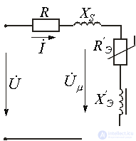 |
where
where
|
Note. 1. If the core contains an air gap of size  , an additional linear inductor with resistance is connected into the equivalent circuit in parallel with the branch containing the nonlinear coil of admittance
  ,
,
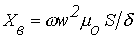
2. Neglecting the active resistance of the winding and the leakage flux, the relation between the equivalent electrical impedance  of the coil and the complex magnetic reluctance
  of the core is determined by

or
 .
.
Transformer with a ferromagnetic core
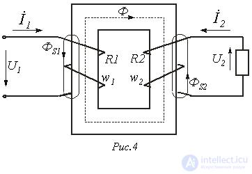
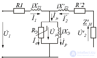
A transformer with a ferromagnetic core is shown in Fig. 4. Here  and
and  are the active resistances of the primary and secondary windings with numbers of turns
  and
and  respectively.
  is the main flux closing through the core.
  and
and  are the leakage fluxes of the primary and secondary windings, to which correspond the leakage inductances
  and
and  and the leakage reactances
  and
and  .
.
The main relations, equivalent circuit, and phasor diagram for a transformer with a ferromagnetic core are given in Table 2.
Table 2. Transformer with a ferromagnetic core
|
Type of information Equations, relations, phasor diagram |
Note |
|
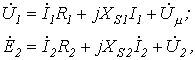
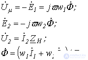
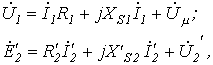
Equations for the primary and secondary circuits
where
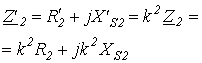
Transformation ratio
Secondary-circuit parameters referred to the primary: voltage across the load
current
EMF
secondary winding resistance
load resistance
Equations of the referred (equivalent) transformer
where
|
For properly designed transformers under a load close to rated,
|
|
Equivalent circuit
|
The expressions for |
|
Phasor diagram 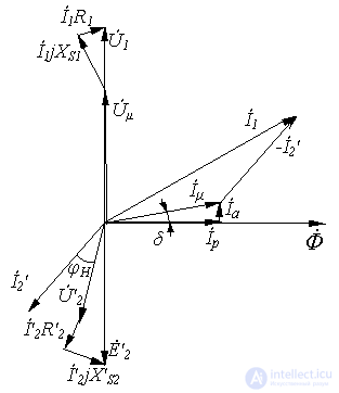 |
The diagram is constructed starting from the secondary loop, for an arbitrary position of
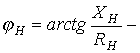
- load angle |
References
Review questions and problems
Answer:  .
.
Answer:  .
.
 and
and  of the core determined?
 , cross section
  , length
  , and air gap
  is connected to an AC voltage
  ; the number of winding turns is
  . Neglecting leakage and core-steel losses, and taking the active resistance of the winding as 100 Ohm, determine the current drawn and the active power.
 and frequency
  at the terminals of a choke, the current in its winding is
  , and the power consumed is
  . The number of turns of the choke winding is
  , and its active resistance is
  . Measurements showed that the maximum value of the working flux in the core is
  . Determine the parameters of the elements of the parallel equivalent circuit of the choke.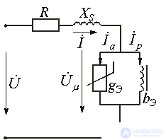










 and
and  are the same as for a coil with a ferromagnetic core (see Table 1)
 .
.

Comments