
Lecture
Equivalent circuit (substitution circuit, equivalent substitution circuit) of a network - an electrical circuit in which all real elements are replaced by their equivalent circuits.
The equivalent circuit (substitution circuit, equivalent substitution circuit) of a real circuit element is an electric circuit consisting of idealized circuit elements, the calculated voltages and currents at whose terminals coincide, to within some error, with the measured currents and voltages at the terminals of the real element. The equations for the currents and voltages of the equivalent circuit of a real element constitute its mathematical model.
One of the main tasks of electronics is the calculation of electric circuits, that is, obtaining detailed quantitative information about the processes occurring in that circuit. However, calculating an arbitrary circuit made up of real electronic components is practically impossible. The calculation is hampered by the fact that there simply are no methods for a mathematical description of the behavior of real electronic components (for example, a transistor) as a single whole. Values of individual parameters and experimentally obtained dependences are available, but combining them into a single exact formula that fully describes the behavior of the component is in most cases not feasible.
On the other hand, idealized basic elements of electronic circuits (for example, an ideal resistor) are described by an extremely simple mathematical apparatus. However, they do not exist in the real world. Thus, any resistor (a real element) has a number of parasitic parameters: inductance, capacitance, temperature dependences, etc.
The introduction of the concept of an equivalent circuit makes it possible to «link» the world of real components with the world of their ideal approximations. An equivalent circuit is a circuit made up only of ideal components that functions in approximately the same way as the original circuit. The equivalent circuit of a real element can, if necessary, reflect various parasitic effects: leakage, internal resistances, etc. Depending on the required accuracy, many substitution circuits for one and the same real element have been developed and continue to be developed. For example, hundreds of substitution circuits (models) are known for different types of transistors.
The idealized elements listed below are used in equivalent circuits. It is also assumed that the geometric dimensions of the equivalent circuit are so small that any long-line effects are absent, that is, the equivalent circuit is treated as a lumped-parameter system.
For any electrical circuit, any number of different equivalent circuits can be constructed — their number is limited only by considerations of practicality. For a single circuit it makes sense to construct several equivalent circuits for the following reasons:
An equivalent circuit is a linear system, so the nonlinear effects of real circuits cannot be modeled by constructing equivalent circuits.
A partial way out of this difficulty is to consider the nonlinear system in a small-signal approximation for a specific operating point, in which case the nonlinear effects are small and can be neglected. This approach does not describe the nonlinear effects, but merely limits the treatment to the case in which they are negligibly small.
The equivalent circuit of a real element, described by ordinary differential equations, cannot correspond absolutely exactly to the real element, whose electrical processes are described by partial differential equations (for example, many characteristics of a semiconductor diode can be obtained from the solution of Poisson's equation for a p — n-junction).
The substitution circuit of a power supply system (PSS) is constructed on the basis of its computational diagram for the initial instant of the transient process. The transition from the computational diagram to the substitution circuit consists in replacing the computational diagram with an equivalent electric circuit that includes EMF sources and constant resistances, and in converting the element parameters and EMFs of the various voltage stages of the PSS to base conditions (to a single voltage stage chosen as the base one).
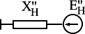
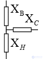
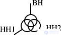
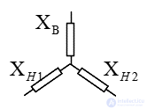
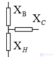
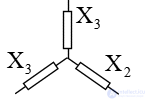
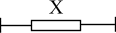
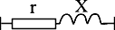
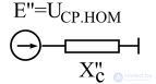
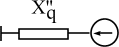
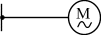
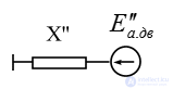
The substitution circuit of the PSS is a combination of the substitution circuits of its individual elements, connected to one another in the same sequence as in the computational diagram (Table 1.2.).
Table 1.2. Computational diagrams and substitution circuits of PSS elements
|
Name of element |
Diagrams |
|
|
Computational |
Substitution |
|
|
Generator, synchronous condenser |
|
|
|
|
|
|
|
Synchronous motor |
|
|
|
Induction motor |
|
|
| Generalized load |  |
 |
| Two-winding transformer |  |
 |
| Three-winding transformer |  |
 |
|
Three-phase transformer with split LV winding |
 |
 |
| Three-phase autotransformer |  |
 |
| Reactor |  |
 |
| Split-winding reactor |  |
 |
| Overhead line |  |
 |
| Cable line |  |
 |
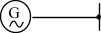
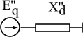
 Equivalent source of the system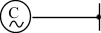


Comments