
Lecture
To calculate unsymmetrical modes it is necessary to know the equivalent values of the EMFs and impedances of the positive-, negative- and zero-sequence equivalent circuits with respect to the point at which the given asymmetry has arisen. The resulting EMF is determined according to the well-known rules of electrical engineering, regardless of the type of asymmetry involved. As for obtaining the resulting impedances, it must be kept in mind that there is a fundamental difference in the transformation of the circuits for transverse and longitudinal asymmetries.
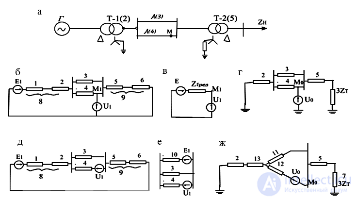
Fig. 6.8. Example of constructing the individual-sequence circuits and determining the resulting impedances for transverse (b, c, d) and longitudinal (e, f, g) asymmetries at point M of the original circuit (a)
For a transverse asymmetry at point M, the positive-sequence equivalent circuit has the form shown in Fig. 6.7,b. The elements 1 and 2, and likewise 5 and 6, connected in series in it, are denoted by the numbers 8 and 9 respectively. To determine the resulting EMF and impedance with respect to point M, it is sufficient to replace branch 9 with E = 0 and the branch obtained by combining element 8 with the parallel-connected elements 3 and 4 and having EMF E, with a single equivalent branch (Fig. 6.8,c).
The negative-sequence circuit and its transformations are analogous, except that it has no source EMFs.
The zero-sequence circuit (Fig. 6.8, d) is easily transformed by successive series and parallel addition of branches.
Now suppose a longitudinal asymmetry arises at point M. In this case the positive-sequence voltage must be inserted into a break in the circuit of element 4 (Fig. 6.8,e). To determine the resulting EMF and impedance at point M in this case, elements 8 and 9 must first be added in series. Then the resulting branch 10 with EMF E and branch 3 (Fig. 6.8,f) must be replaced by an equivalent one, which gives the sought resulting EMF with respect to point M; then, to find the resulting impedance with respect to the same point, the impedance of element 4 must be added to the impedance of the resulting equivalent branch. The negative-sequence circuit is analogous to the circuit of Fig. 6.7,e; it merely lacks the source EMF. Its resulting impedance is found in the same way as for the positive-sequence circuit.
In the zero-sequence circuit (Fig. 6.8, g), the double-circuit line is introduced by its three-ray equivalent circuit with elements 11, 12 and 13, in order to take into account the mutual induction between the circuits, which are now under different conditions. To find the resulting impedance of the circuit here, the impedance of element 11 must be added to the sum of the impedances of elements 2, 13, 5 and 7 (the last of which enters at triple its value), and then the impedance of element 12 must be added.

Comments