
Lecture
Transient conditions of a power supply system are transitions of the system from one state to another. A condition is a state of the system characterized by indicators that quantitatively define its operation. These indicators are called the condition parameters. They include the values of power, voltage, current, the phase-shift angles of EMF, voltage and current vectors, frequency, etc. The condition parameters are related by equations that involve the system parameters.
System parameters are indicators that qualitatively define the physical properties of the system and depend on the connection scheme of its elements and the assumptions adopted. The system parameters include the values of total, reactive and active resistances, transformation ratios, time constants, gain factors, etc. For example, the current in a certain branch of a complex system
I1 = E1 Y11 + E2 Y12 + … Ek Y1k
is determined by the parameters (EMF E1, E2, … E k) and the system parameters (admittances Y11, Y12, … Y1k ).
A number of system parameters depend to some extent on the operating condition. Such a system would be nonlinear. However, in many practical problems the parameters of this system can be assumed constant, treating the system as linear.
Another type of nonlinearity in a power supply system, usually taken into account in the analysis, is due to the character of the relationship between its condition parameters. For example, active power is related to voltage by a quadratic dependence, or to the load angle by a sinusoidal one.
Steady-state operating conditions of electric circuits are conditions in which the circuit parameters are constant: voltage, current, resistances, etc. If, after a steady-state condition has been reached, the voltage changes, the current will also change. The transition from one steady-state condition to another does not occur instantaneously, but over a certain period of time (Figure 1).
The processes that occur in circuits during the transition from one steady-state condition to another are called transient processes. Transient processes arise whenever the circuit parameters change abruptly. The instant of the abrupt change in the operating condition of the electric circuit is taken as the initial instant of time, relative to which the state of the circuit is characterized and the transient process itself is described.
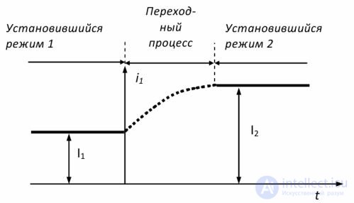
Fig. 1. Conditions arising in an AC circuit
The duration of a transient process can be very short, measured in fractions of a second, but the currents and voltages or other parameters characterizing the process can reach large values. Transient processes are caused by switching in the circuit.
Switching is the closing or opening of the contacts of switching devices. Two switching laws are used in the analysis of transient processes.
The first switching law: the current flowing through an inductive coil before switching is equal to the current through the same coil immediately after switching. That is, the current in an inductor cannot change abruptly (in a step).
The second switching law: the voltage across a capacitive element before switching is equal to the voltage across the same element after switching. That is, the voltage across a capacitive element cannot change abruptly (in a step). For a series connection of a resistor, an inductor and a capacitor, the following relations hold

In the circuit under consideration, when the reactances Xl and Xc are equal, so-called voltage resonance occurs. Since these reactances depend on frequency, resonance occurs at a certain resonant frequency ω0.
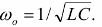
In this case the total circuit impedance is minimal and purely resistive, Z = R, and the current reaches its maximum value. At ω < ω0 the load is capacitive in nature, at ω >ω0 it is inductive.
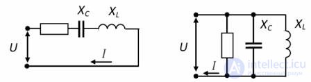
It should be noted that the sharp increase in circuit current at resonance is accompanied by an increase in Xl and Xc. These voltages can become considerably greater than the voltage U applied to the circuit terminals, which is why voltage resonance is a phenomenon that is hazardous for electric power installations.
The currents in the branches of parallel-connected circuit elements have a corresponding phase shift relative to the common circuit voltage. Therefore the total circuit current equals the sum of the currents of its individual branches, taking the phase shifts into account, and is determined by the formula

When the reactances Xl and Xc are equal, in a circuit with parallel-connected elements current resonance occurs. At resonance the current reaches its maximum value, and the power factor reaches its maximum (cosφ = 1). The resonant frequency value is determined by the formula
The currents in the branches containing L and C can, at resonance, be larger than the total circuit current. The inductive and capacitive currents are opposite in phase, equal in magnitude, and mutually compensate with respect to the power source. That is, an exchange of energy takes place in the circuit between the inductor and the capacitor.
A condition close to current resonance is widely used to increase the power factor of electric power consumers. This gives a significant economic effect due to reduced conductor loading, lower losses, and savings in materials and electric energy.
The operating conditions of a power supply system are divided into two large groups: steady-state conditions and transient conditions (non-steady-state, non-stationary).
Within these groups, several types of conditions are distinguished:
normal steady-state – long-duration conditions, with respect to which the main technical and economic characteristics of the power supply system are determined during design;
normal transient– conditions during which the system transitions from one operating state to another;
emergency – steady-state and transient conditions for which the technical characteristics of devices intended to clear the fault are determined, and the conditions for further operation of the system are ascertained;
post-emergency steady-state conditions, which are generally characterized by a change in the normal operation of the system, for example, the disconnection of some element or a number of elements.
Any transient conditions arise as a result of changes in system parameters caused by some reason. These causes, called disturbing actions, lead to the appearance of initial deviations of the condition parameters – condition disturbances.
The condition of a system is not something unified; it consists of a multitude of different processes. A process is understood as a sequential succession of certain phenomena. In power supply systems there is a huge number of such processes making up any condition. The electromagnetic processes considered here are the sequential change of electromagnetic phenomena in electric circuits.
The main causes giving rise to electromagnetic transient processes:
switching electric motors and other elements of the power supply system on and off;
short circuits in the system, as well as repeated closing and opening of a short-circuited circuit;
the occurrence of local longitudinal asymmetry, for example, the break of one or two phases of a power line;
operation of excitation control devices of synchronous machines (excitation forcing and field suppression);
asynchronous (out-of-phase) switching-in of synchronous machines.
A short circuit is any connection between phases that is not provided for by normal operating conditions; in systems with a grounded neutral, it also includes the connection of one or two phases to ground.
In systems with isolated neutrals, or with neutrals grounded through special compensating devices, the connection of one phase to ground is called a simple fault. In this type of fault, the current flow is due mainly to the capacitance of the phases with respect to ground.
When a short circuit occurs in an electrical system, the circuit impedance decreases, which leads to an increase in the currents in individual branches of the system compared with the currents of the normal condition. At the same time, this causes a drop in voltage in the power supply system, especially near the location of the short circuit.
At the point of the fault there is usually some transition resistance, determined mainly by the resistance of the electric arc. The electric arc arises either right at the start of the fault (flashover or breakdown of insulation), or after some time, when the element that caused the fault burns through.
When the currents are sufficiently large, the arc resistance is approximately constant and, by its nature, almost purely resistive. As the current decreases and the arc length increases, which occurs during transient processes, its resistance increases.
Short circuits are called solid (metallic) faults if the transition resistance is so small that it can be neglected.
All else being equal, the current for a solid (metallic) short circuit is the largest, and is therefore the design value used for selecting electrical equipment.
In three-phase systems with a grounded neutral, the following types of short circuits at a single point are distinguished: three-phase, two-phase, single-phase-to-ground, and two-phase-to-ground.
A three-phase short circuit is symmetrical, since in this case all phases remain under identical conditions. All other types of short circuits produce asymmetrical systems, since in each of them the phases are already under unequal conditions.
The relative probability of the various main types of short circuit is given in Table 1.1. As can be seen from this table, the most frequent is the single-phase-to-ground short circuit, while three-phase short circuits are relatively rare. At the same time, the most severe operating conditions for electrical equipment occur precisely during a three-phase short circuit, so it is, as a rule, the decisive case for the final judgment on the possibility of operation under short-circuit conditions.
The study of the three-phase short-circuit process itself is especially important because the method of symmetrical components, which is the basis for calculating asymmetrical conditions, makes it possible to calculate the positive-sequence currents and voltages and to determine them as the corresponding quantities for certain equivalent three-phase faults.
It should be noted here that the process of switching on any three-phase load, for example a motor, can essentially be regarded as a three-phase short circuit behind a certain impedance.
Table 1.1 Types of short circuits and their relative probability
|
Types of short circuits |
Symbol designation |
Basic diagram |
Relative probability of SC, % |
|
Three-phase |
K(3) |
|
5 |
|
Two-phase |
K(2) |
|
10
|
| Single-phase | K(1) | 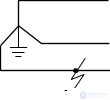 |
65 |
|
Two-phase to ground |
K(1.1) | 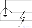 |
20 |
Asymmetrical short circuits, as well as unbalanced loads, represent various types of transverse asymmetry.
The disconnection of one or two phases, or a violation of symmetry in some intermediate element of a three-phase circuit, is called longitudinal asymmetry.
In operating practice, cases of the simultaneous occurrence of several asymmetries of the same or different types are possible. For example, broken conductors may occur simultaneously with a ground fault on one of them, a double ground fault, i.e. a simultaneous ground fault on different phases at different points of a network operating with an isolated neutral, and other complex faults.
The phenomena noted above determine the extreme nature of the processes in many elements of the system, and thereby predetermine the task of assessing the reliability of operation of the entire system and of individual consumers under operating conditions.
Short circuits are associated with a decrease in circuit impedance, and consequently with an increase in the current in the elements of the system and a drop in voltage at the consumers.
The prolonged flow of large fault currents through the elements of the system can promote thermal and mechanical destruction of the elements. A drop in voltage can cause disruption of technological processes due to the braking and stalling of motors.
Analysis of the processes considered, taking into account the full set of influencing factors, is extremely complex and practically infeasible.
These problems can be solved by using certain assumptions that simplify the analysis of the processes:
Absence of magnetic-system saturation (this reduces any circuit to a linear one and allows the superposition principle to be used).
Absence of magnetizing currents in transformers and autotransformers (this assumption is used in all cases except for 3-limb transformers with a Y0/Y0 connection).
Absence of asymmetry in the 3-phase system, neglect of capacitive admittances (except for ground faults and overhead lines above 220 kV).
Approximate accounting of loads (depending on the stage of the transient process, the load is characterized by a certain constant impedance).
Absence of active resistances (this assumption is applied when studying transient processes in the main links of the high-voltage part of the system).
Absence of generator swings (rotor-angle oscillations).

Comments