
Lecture
A distinction is made between exact and approximate reduction of parameters when constructing the substitution circuit of a power supply system (PSS).
In exact reduction, the actual transformation ratios of the transformers between the voltage stages of the PSS computational diagram are used for the EMFs and element parameters. Suppose the circuit of a certain voltage stage of the diagram is connected to the stage chosen as the base one through a series of consecutively connected transformers with transformation ratios K1, K2, . . . . .Kn. Using the known relations for EMF (voltage), current and resistance when referring them from one side of a transformer to the other, general expressions can be written for determining the values of individual quantities of this circuit referred to the base stage:
;
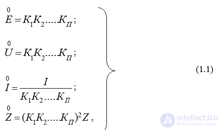
that is, the true (actual) values must be recalculated as many times as there are transformers along the path between the circuit being reduced and the adopted base stage.
In these and subsequent expressions, the transformation ratio of each transformer or autotransformer (whether step-up or step-down) is understood as the ratio of the phase-to-phase no-load voltage of its winding facing the base voltage stage to the corresponding voltage of its other winding, located closer to the stage whose elements are to be reduced.
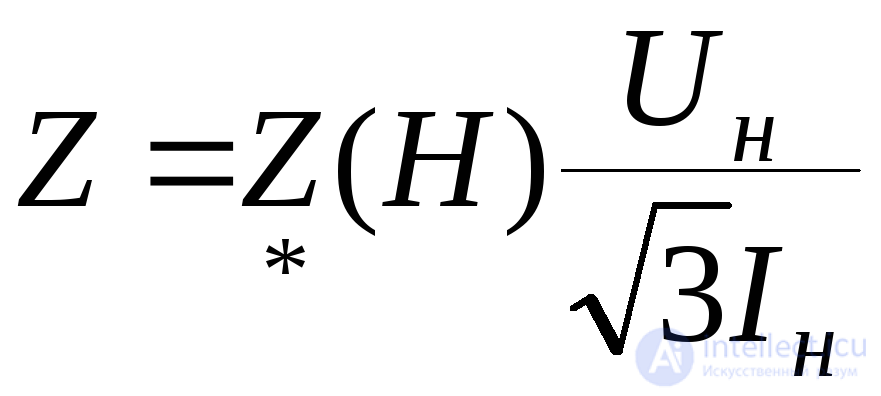
If the quantities are given in per-unit values, their values in named (absolute) units are first determined. Thus, the resistance of an element for which its per-unit value  (Nom) is known will be:
 . (1.2)
Unlike the reduction discussed above based on actual transformation ratios, practical calculations often use approximate reduction, which makes it possible to obtain an approximate substitution circuit considerably faster and more simply. In this case it is recommended to replace the actual no-load voltages of the transformers (autotransformers), as well as the rated voltages of the various elements (except reactors) of the computational diagram that are on the same transformation stage, with the average rated voltages Uavg. The scale of these voltages is as follows: 515; 340; 230; 158; 115; 37; 24; 20; 18; 15,75; 13,8; 10,5; 6,3; 3,15; 0,69; 0,4; 0,23; 0,127 kV. Consequently, under approximate reduction, the conversion expressions take a simpler form
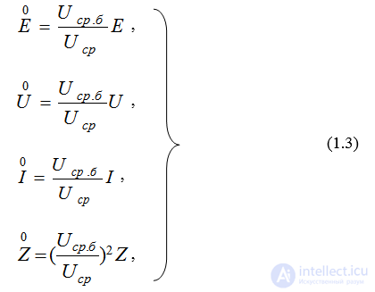
where Uavg – is the average rated voltage of the stage from which the recalculation is performed;
Uavg.b – the same for the chosen base stage.
If an element is given by its per-unit resistance Z(Nom), then its resistance in named units can be determined from (1.2), substituting for Unom the average rated voltage of the base stage.
Approximate reduction of the circuit introduces a certain error into the calculation. To obtain more reliable results, the circuit should be reduced using actual transformation ratios, especially when transformers with wide voltage regulation are present.

Comments