
Lecture
Let us consider the electrical devices of sinusoidal-current circuits and methods for analyzing their operating modes
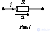
An ideal resistive element has neither inductance nor capacitance. If a sinusoidal voltage  is applied to it (see Fig. 1), then the current i through it will be equal to
 . . |
(1) |
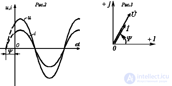
Relation (1) shows that the current has the same initial phase as the voltage. Thus, if the signals u and i, are applied to the inputs of a dual-beam oscilloscope, the corresponding sinusoids on its screen will pass through zero simultaneously (see Fig. 2), i.e., on a resistor the voltage and current are in phase.
From (1) it follows that:
 ;
;
 .
.
Passing from the sinusoidal functions of voltage and current to the corresponding complexes:
 ;
;
 ,
,
- let us divide the first of them by the second:
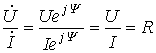
or
 . . |
(2) |
The result obtained shows that the ratio of the two complexes is a real constant. Consequently, the corresponding voltage and current vectors (see Fig. 3) coincide in direction.
Capacitive element - an idealized element of an electric circuit, whose properties approximate those of a capacitor and reflect its basic property of storing (releasing) electrical energy in an electric field.
Capacitor - a device that has two conductors 1 (usually plates), Fig. 2.3a, separated by a dielectric 2, whose properties are characterized by the absolute permittivity ea.
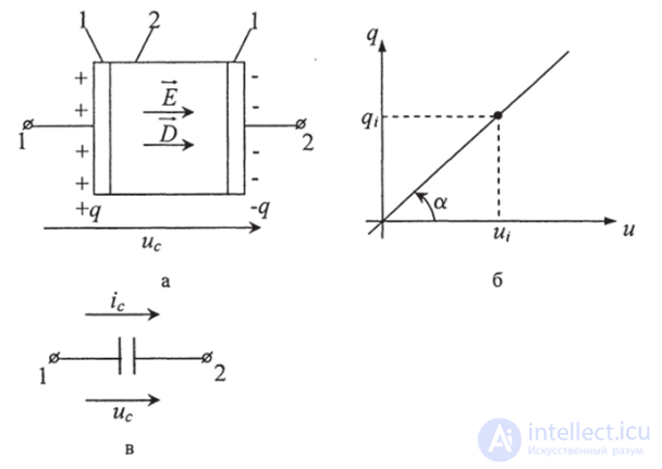
Fig. 2.3. Capacitor with a linear coulomb-volt characteristic:
a - capacitor; b - coulomb-volt characteristic; c - symbols used in the diagram
Fig. 2.36 shows the coulomb-volt characteristic of a capacitor with a dielectric whose dielectric constant ea - const.
An ideal capacitive element has neither resistance (conductance) nor inductance. If a sinusoidal voltage  is applied to it (see Fig. 4), then the current i through it will be equal to
 . . |
(3) |
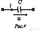
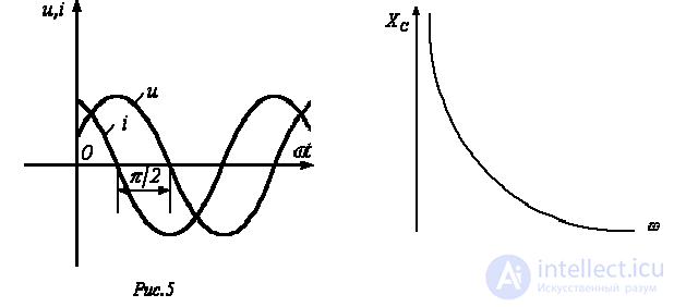
The result obtained shows that the voltage on the capacitor lags the current in phase by  /2. Thus, if the signals u and i are applied to the inputs of a dual-beam oscilloscope, the picture on its screen will correspond to Fig. 5.
From (3) it follows that:
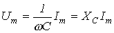 ;
;
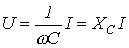 .
.
The introduced parameter  is called the reactive capacitive resistance of the capacitor. Like the resistive resistance,
  has the dimension of ohms. However, unlike R this parameter is a function of frequency, as illustrated in Fig. 6. From Fig. 6 it follows that at
  the capacitor represents an open circuit for current, and at
 .
.
Passing from the sinusoidal functions of voltage and current to the corresponding complexes:
 ;
;
 ,
,
- let us divide the first of them by the second:

or
 . . |
(4) |
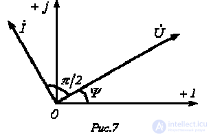
In the last relation,  is the complex impedance of the capacitor. Multiplying by
  corresponds to rotating the vector through the angle
  clockwise. Consequently, equation (4) corresponds to the phasor diagram shown in Fig. 7.
Inductive element- an idealized element of an electric circuit, whose properties approximate those of an inductor and reflect its basic property of storing (releasing) electrical energy in a magnetic field.
An inductor(device) (Fig. 2.1a) is, as a rule, a former 1, onto which a large number of turns n> of conductor - wire 2 - are wound. Inside the coil former there is a dielectric, in particular air, with permeability equal to unity (/?=1).
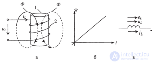
Fig. 2.1. Inductor with a linear weber-ampere characteristic: a - inductor; b - weber-ampere characteristic, c - schematic symbol
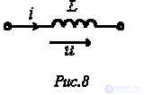
An ideal inductive element has neither resistance nor capacitance. Suppose the current flowing through it (see Fig. 8) is given by the expression  . Then for the voltage across the terminals of the inductor we can write
 . . |
(5) |
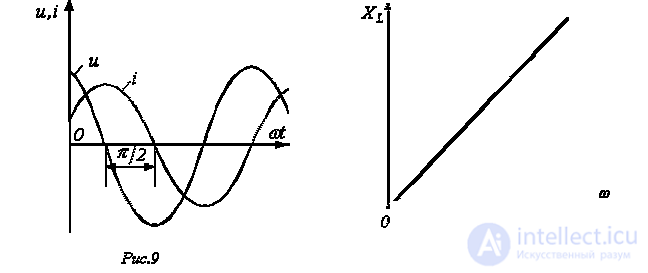
The result obtained shows that the voltage across the inductor leads the current in phase by /2. Thus, if the signals u and i are applied to the inputs of a dual-beam oscilloscope, the picture on its screen (for an ideal inductive element) will correspond to Fig. 9.
From (5) it follows that:

 .
.The introduced parameter  is called the reactive inductive resistance of the coil; its dimension is ohms. As with the capacitive element, this parameter is a function of frequency. However, in this case the dependence is linear, as illustrated in Fig. 10. From Fig. 10 it follows that at
  the inductor offers no resistance to the current flowing through it, and at
 .
.
Passing from the sinusoidal functions of voltage and current to the corresponding complexes:
 ;
;
 ,
,
let us divide the first of them by the second:

or
 . . |
(6) |
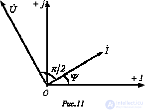
In the resulting relation,  is the complex
impedance of the inductor. Multiplying by  corresponds to rotating the vector through the angle
  counterclockwise. Consequently, equation (6) corresponds to the phasor diagram shown in Fig. 11

Suppose that in the branch of Fig. 12,  . Then
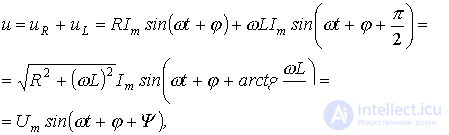 where
where
 , with the range of variation of
 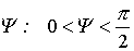 .
.
Equation (7) can be matched with the relation
 ,
,
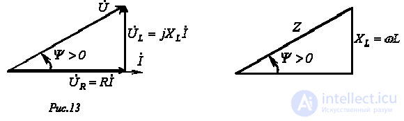
which, in turn, corresponds to the phasor diagram in Fig. 13. The vectors in Fig. 13 form a figure called the voltage triangle. Similarly, the expression

can be represented graphically by the impedance triangle (see Fig. 14), which is similar to the voltage triangle.
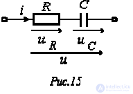
Omitting the intermediate steps, using relations (2) and (4) for the branch in Fig. 15 we can write
. , , |
(8) |
where

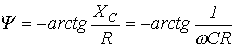 , with the range of variation of
  .
.
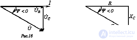
Based on equation (7), the voltage triangle (see Fig. 16) and the impedance triangle (see Fig. 17) can be constructed, and they are similar.
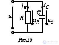
For the circuit in Fig. 18 the following relations hold:
 ;
;
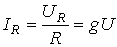 , where
  [S] – active conductance;
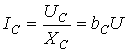 , where
  [S] – reactive conductance (susceptance) of the capacitor.
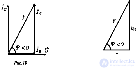
The phasor diagram of the currents for this circuit, called the current triangle, is shown in Fig. 19. It corresponds to the equation in complex form
 ,
,
where 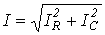 ;
;
 - complex admittance;
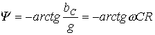 .
.
The admittance triangle, similar to the current triangle, is shown in Fig. 20.
For the complex impedance of the circuit in Fig. 18 we can write
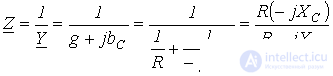 .
.
It should be noted that the result obtained is analogous to the expression, known from the physics course, for the equivalent resistance of two resistors connected in parallel.
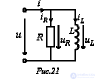
For the circuit in Fig. 21 we can write
 ;
;
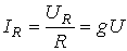 , where
  [S] – active conductance;
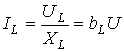 , where
 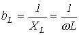 [S] – reactive conductance (susceptance) of the inductor.
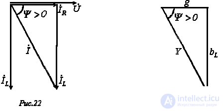
The phasor diagram of the currents (Fig. 22) for this circuit corresponds to the equation in complex form
 ,
,
where 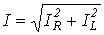 ;
;
 - complex admittance;
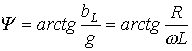 .
.
The admittance triangle, similar to the current triangle, is shown in Fig. 23.
The expression for the complex impedance of the circuit in Fig. 21 has the form:
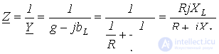 .
.
1. Fundamentals of Circuit Theory: A university textbook /G.V. Zeveke, P.A. Ionkin, A.V. Netushil, S.V. Strakhov. –5th ed., revised. –Moscow: Energoatomizdat, 1989. -528 p.
2. Bessonov L.A. Theoretical Foundations of Electrical Engineering: Electric Circuits. A textbook for university students of electrical engineering, power engineering, and instrument-making specialties. –7th ed., revised and expanded. –Moscow: Vysshaya Shkola, 1978. –528 p.
1. What is the essence of reactive resistances?
2. Which of the elements - a resistor, an inductor, or a capacitor - can be used as a shunt for observing the waveform of the current?
3. Why are inductors and capacitors not used in direct-current circuits?
4. In the branch of Fig. 12,  . Determine the complex impedance of the branch if the current frequency is
  .
.
Answer: 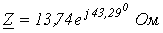 .
.
5. In the branch of Fig. 15,  . Determine the complex impedance of the branch if the current frequency is
  .
.
Answer:  .
.
6. In the circuit of Fig. 18,  . Determine the complex admittance and impedance of the circuit for
  .
.
Answer:  ;
; .
.
7. The current flowing through an inductor  varies according to the law
  A. Determine the RMS-value complex of the voltage across the inductor.
Answer:  .
.

Comments