
Lecture
The main task of operating electrical networks is to maintain the necessary transfer capacity and sufficient voltage in them. Several modes of electrical networks are distinguished. The mode parameters include the indicators of frequency, voltage and power transmission.
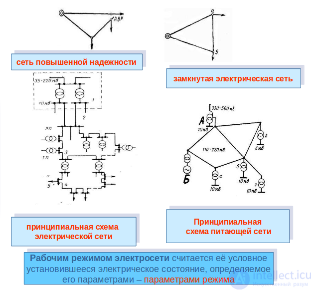
A power supply system (PSS) can be in various operating modes: normal, abnormal and emergency. Let us consider these modes.
The operating mode of an electrical network is considered to be its conditional steady-state electrical condition, determined by its parameters – the mode parameters.
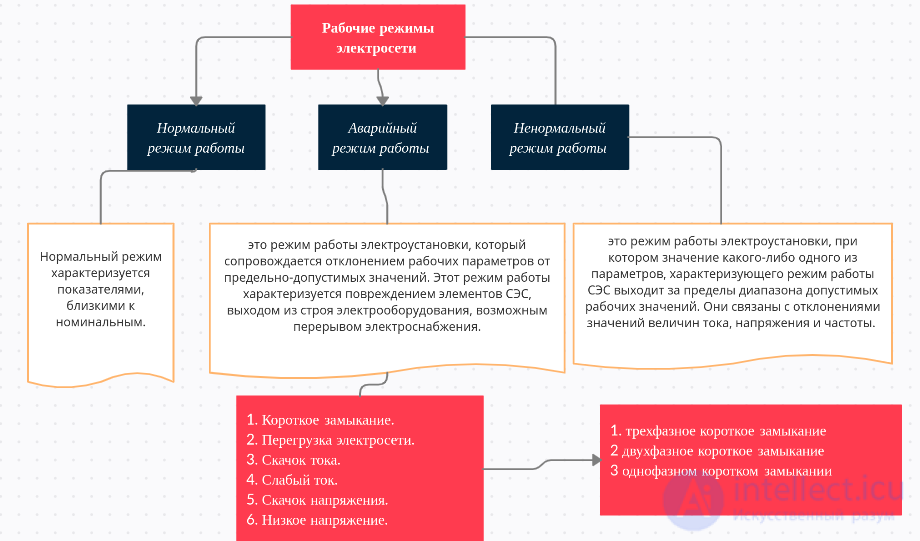
Normal operating mode — is such an operating mode of an electrical installation in which the supply of electric power to any consumers of the required quality is ensured. In this case, the power quality indicators are within the limits established by GOST 32144–2013.
Emergency operating mode — is an operating mode of an electrical installation that is accompanied by a deviation of the operating parameters from their maximum permissible values. This operating mode is characterized by damage to elements of the PSS, failure of electrical equipment, and a possible interruption of the power supply.
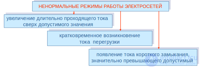
Abnormal operating mode — is an operating mode of an electrical installation in which the value of any one of the parameters characterizing the operating mode of the PSS goes beyond the range of permissible operating values. These are associated with deviations in the values of current, voltage and frequency. Abnormal operating modes can be dangerous for the equipment or for the stable operation of the power system.
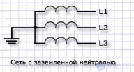
The emergency operating modes of electrical installations include short circuits: three-phase (K(3)), two-phase (K(2)), two-phase-to-ground (K(1.1)), single-phase (K(1)). All these types of faults apply to networks with a grounded neutral operating mode [1, 2, 4, 5].
Short circuit (SC) — is an electrical connection of two points of an electrical circuit with different potential values, not provided for by the design of the device and disrupting its normal operation or condition, in which the load resistance is less than the internal resistance of the power source. In addition, a short circuit can occur when the insulation of current-carrying elements is damaged [1, 2, 4, 5].
Flows of reactive electric energy at the boundary of balance ownership of electrical networks (flows of reactive electric energy) - a component of the physical processes of transmission, distribution and consumption of active electric energy, which causes additional technological losses of active electric energy and affects the quality indicators of active electric energy.
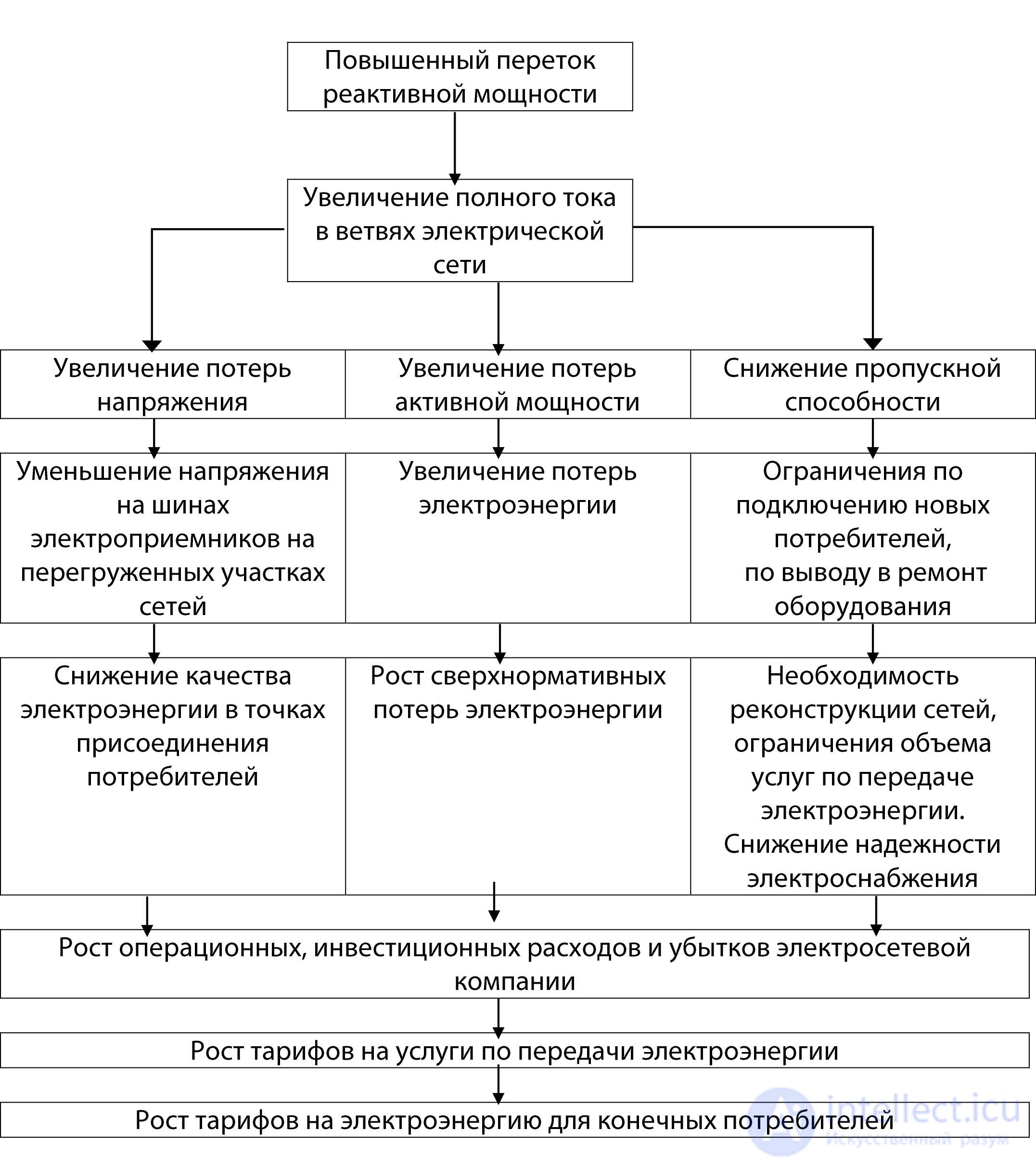
Fig. Consequences of an increase in reactive power flows.
It follows from this goal that increasing the energy efficiency of electrical networks most likely should be understood not only (and often not so much) as reducing losses in the networks, but also as improving the reliability and quality of power supply, as well as increasing the transfer capacity of the networks to ensure non-discriminatory access of consumers to the networks. These indicators are technologically closely interrelated. As a rule, their integrated consideration is especially necessary when developing capital-intensive measures for the modernization and development of electrical networks, connecting new consumers and generating sources to them, and introducing new equipment and technologies for the transmission and distribution of electric power.
Depending on the value of the main parameters — frequency and voltage, a distinction is made between the normal mode, emergency mode, and the summer and winter modes of electrical networks.
Normal mode of electrical networks
Normal operating mode is characterized by parameters close to rated values. This mode ensures smooth control of power plant operation, minimizes electrical energy losses in the network, and allows convenient operational switching. The normal mode of the electrical network ensures an uninterrupted supply of electricity to consumers with a sufficient voltage level.
Also considered normal is the mode in which a high-power transformer line is switched on and off, along with moments of high-amplitude voltage fluctuations lasting fractions of a second.
Emergency mode of electrical networks
A mode becomes an emergency mode when, during the system's transition from one normal state to another, a sharp change in current frequency and voltage parameters is observed. Emergency variants of electrical network operation include deviations such as:
1. Short circuit. Characterized by exceeding the rated voltage by tens of times. Manifests as a bright flash of light from a lamp.
2. Network overload. Announces itself by heating of an outlet or switch, up to the point of them catching fire.
3. Current surge. A consequence of a brief voltage overshoot. When switched on, an incandescent lamp burns out.
4. Weak current. May be caused by a circuit break. In this case, the incandescent lamp glows dimly.
5. Voltage surge. Most often occurs due to lightning strikes. In most cases this leads to the failure of electrical appliances.
6. Low voltage. Occurs due to a partial circuit break. Prolonged use under low voltage causes appliances to fail.
The summer and winter modes of electrical networks are classified as normal, but they are characterized by significant loads on the system due to high or low temperatures and the effects of adverse weather conditions.
Each of us has encountered a case where, for example, a light bulb starts to «flicker» or becomes too dim (or too bright). Many people do nothing and hope that the «ailment» will cure itself. To review deviations of electrical network operation from the normal state, the concept of the rated value of current (voltage) will be used. The rated value of current (voltage) is its value under normal (fault-free) operation of the electrical network. Let us consider the possible variants of emergency network operation.
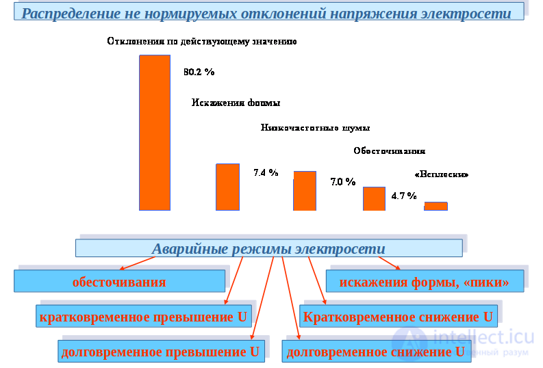
This phenomenon is observed when the current reaches values exceeding the rated value by 10 or more times over a short period of time (seconds, fractions of a second). In this case, the heat released as current passes through the conductor reaches values exceeding the normal value by 100 or more times. A short circuit results from the shorting of the phase and neutral conductors in a single-phase circuit (of the phase and phase/neutral conductors in a three-phase circuit). The consequences of such a short circuit, at best, are a circuit break due to destruction of the wiring and failure of electrical appliances, and at worst, a fire. An external sign of a short circuit can be a very bright flash of light from an incandescent lamp. In this case, it is necessary to de-energize the possible section of the fault (in an apartment or house – the main breaker in the electrical panel).
Overload is caused by the inability of the electrical circuit or a section of it (wiring, switches, outlets, etc.) to operate normally (without overheating, damage, etc.) due to a current flowing through it that exceeds the permissible values for that circuit (or section). The consequences of overload include: conductors (outlets, switches, etc.) heating up to a hot state (slight heating is usually acceptable), the smell of burning wiring, melting, circuit breaks, and fire. In the event of a circuit overload, unnecessary electrical appliances must be switched off, or the entire network de-energized. To prevent the network from being overloaded, only appliances that it is rated for should be connected to it.
This is observed when the current value exceeds its rated value by 3-5 times for a short period of time (fractions of a second). It can result from switching of electrical appliances (of a short-term nature). Many of us have probably been in a situation where, when turning on a light (a fixture with an incandescent lamp), the lamp burned out. This happens because a current exceeding the rated value passed through the filament. This is a natural phenomenon. If a lamp keeps burning out repeatedly, it is worth considering replacing it with a different type of lamp or installing special protective devices.
A common cause of this may be a partial circuit break or a short to the enclosure. In this case, additional resistance appears in the circuit, limiting the current. An indicator of this can be the dim glow of an incandescent lamp. In such a case, it is necessary to diagnose the electrical network and carry out repairs.
This can result, for example, from a lightning strike. In this case, the voltage values will exceed the rated value by tens, hundreds, or even thousands of times. The consequence of such a surge can be failure of the electrical appliances connected to the network. The electrical network can be protected from voltage surges by installing special devices.
This can result from a partial break in the electrical circuit. It can also result from switching of electrical appliances (of a short-term nature). Prolonged operation of electrical appliances at such a voltage can cause them to fail. If diagnostics of the network reveal that the cause is an external source (i.e., low voltage is already arriving at the distribution panel), the problem can be solved by installing special devices.
Important! It should be remembered that many electrical appliances, even if they allow operation with non-rated voltage values (see the device specifications), only allow it briefly. Therefore, in the event of an emergency condition, the network must be de-energized to avoid costly repair or replacement of not only the wiring, outlets, etc., but also of household electrical appliances. In some cases, more serious consequences can be avoided simply by disconnecting the electrical appliance (load) from the network in time, since it is precisely the presence of a switched-on device in the circuit that causes an increase in current and, as a result, faster destruction (burnout) of the wiring, etc.
In a three-phase short circuit, the currents and voltages in all three phases are equal in magnitude, not only at the point of the short circuit, but at any other point in the network: ;  .
.
In a two-phase short circuit, there is no current in the healthy phase, while the faulted phases carry currents that are equal in magnitude and opposite in direction: 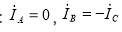 .
.
The voltage between the faulted phases is zero, while the phase voltages are:
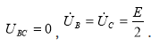 .
.
In a two-phase-to-ground short circuit, the relationships between currents and voltages have the following form: 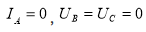 .
.
For networks with a grounded neutral, this type of short circuit is more dangerous compared to a two-phase short circuit because of the significant reduction in line voltages at the fault location.
In a single-phase short circuit, the ratios of currents and voltages take the following form: 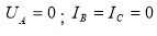 . (This type of short circuit is valid only for networks with a grounded neutral, as is also the case for a two-phase-to-ground short circuit.)
In electrical machines, inter-turn short circuits are possible (a short circuit between turns of the rotor or stator winding, or between turns of transformer windings), as well as a short circuit of the winding to the metal frame of the machine.
A short circuit in any element of the power system can disrupt its operation — the supply voltage of some consumers may drop, which leads to equipment damage; in three-phase networks, short circuits cause voltage asymmetry, disrupting normal power supply. In backbone (interconnected) networks, a short circuit can cause severe system-wide failures [1–5].
Main causes of short circuits
Most often a short circuit occurs through a transition (fault) resistance (through the resistance of the electric arc arising at the point of insulation failure). Sometimes metallic short circuits occur without any transition resistance.
Table 1
Probability of faults occurring inelectrical networks
|
Type of short circuit/fault |
Probability of occurrence |
|
Three-phase — K(3) |
1–7 % |
|
Two-phase — K(2) |
2–13 % |
|
Two-phase-to-ground — K(1.1) |
5–20 % |
|
Single-phase — K(1) |
60–92 % |
|
Single-phase-to-ground fault — Z(1) |
60–92 % |
Other abnormal operating conditions
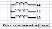
In networks that do not have a directly grounded neutral (isolated, compensated, or resistance-grounded neutral), only three-phase and two-phase short circuits can occur.
In the networks mentioned above (without a grounded neutral), when any of the three phases makes electrical contact with the ground, single-phase-to-ground faults (SPGF) occur, which are classified as abnormal operating conditions (they are not short circuits), since during a single-phase-to-ground fault the network (in the classical case) is not disconnected by relay protection devices and continues to operate. In this case, the voltages on the healthy phases rise to line values. The permissible values of capacitive currents during a single-phase-to-ground fault for networks of various voltage classes are given in Table 2.
Table 2
Permissible values of capacitive current during a single-phase-to-ground fault
|
Voltage class, kV |
Permissible value of capacitive current, A |
|
3–6 |
30 |
|
10 |
20 |
|
15–20 |
15 |
|
35 |
10 |
|
Generator circuits |
5 |
|
Overhead lines on reinforced-concrete poles |
10 |
It is precisely this operating mode that currently arouses lively interest, since to this day no one has managed to create universal selective protection against single-phase ground faults, so the relevance and promise of developing such protection are beyond doubt.
In addition to everything listed above, the overload mode should be highlighted as one of the varieties of abnormal operating modes. These include: equipment overload from exceeding the rated current value, and equipment overload from exceeding the rated voltage value. Exceeding the rated current value causes increased insulation wear, which leads to its damage. Exceeding the rated voltage value shortens the service life of electrical equipment and increases the likelihood of faults occurring.
In conclusion, let us present a table of neutral operating modes of power supply systems and the types of faults that can occur in each specific case.
Table 3
Types of faults in power supply systems
|
Type of fault or damage |
|
|
|
Three-phase — K(3) |
+ |
+ |
|
Two-phase — K(2) |
+ |
+ |
|
Two-phase-to-ground — K(1.1) |
+ |
|
|
Single-phase — K(1) |
+ |
|
|
Single-phase fault to ground — Z(1) |
+ |
three-phase circuits


Comments