
Lecture
 Rb = Rc;
a) four-wire star
 ;
;

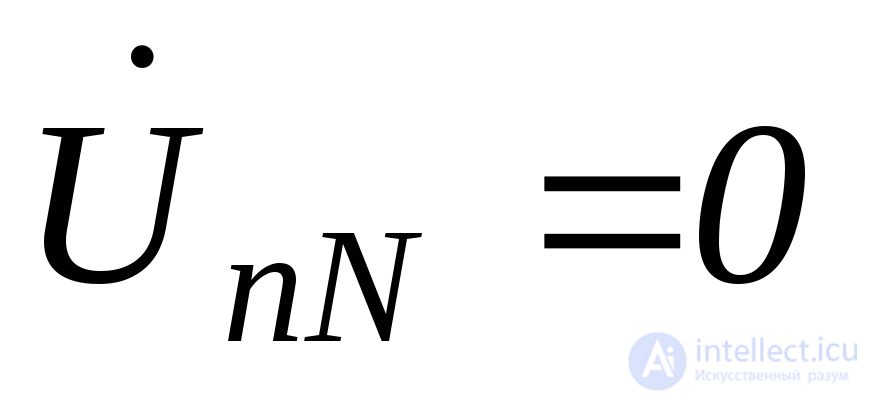
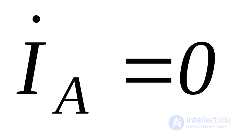
The vector diagram (Fig. 4.67) demonstrates the operation of the four-wire system.
b) three-wire star
 .
.
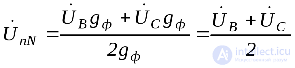
The displacement voltage 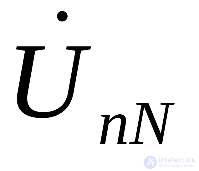 can also be determined by the intersection (arc) method, as shown in Fig. 4.68.
 ;
;
 ;
;
 .
.
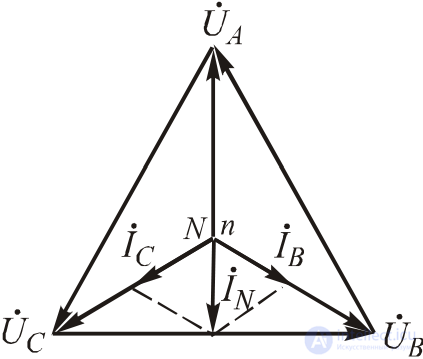
Fig.4.67. Vector diagram for a phase break in a four-wire system
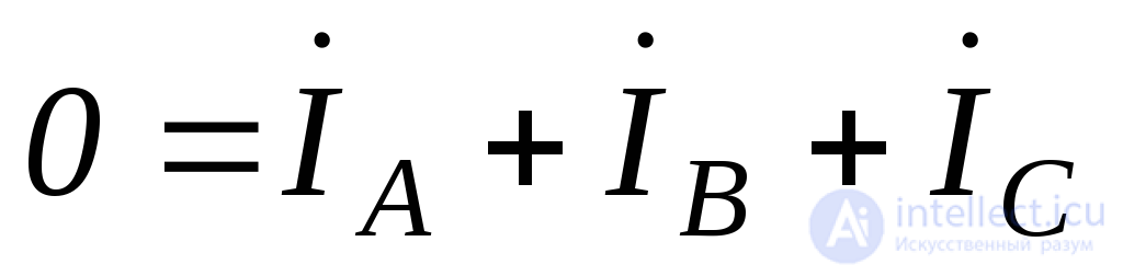
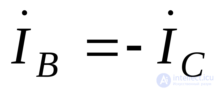
The currents in phases b and c must be in antiphase.
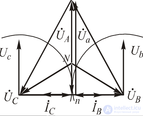
Fig.4.68. Vector diagram for a phase break in a three-wire system
Ra = 0; Rb = Rc;
a) four-wire star
In a four-wire system, a short circuit of a load phase results in a short circuit of the corresponding source phase.
b) three-wire star
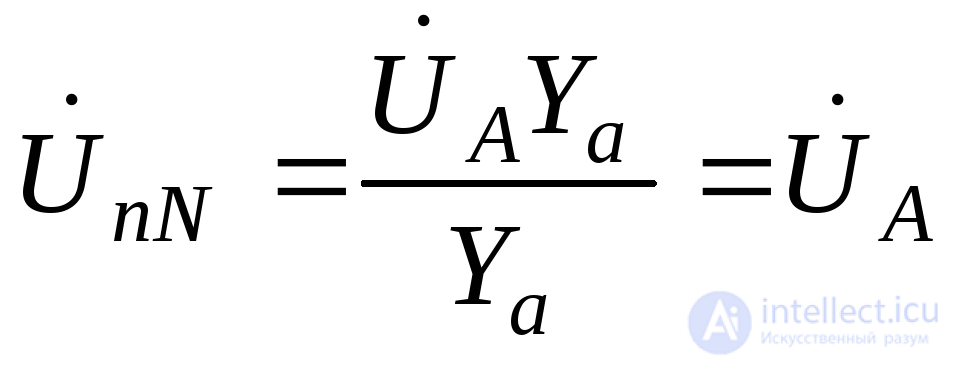 .
.
Phase voltages of the load:
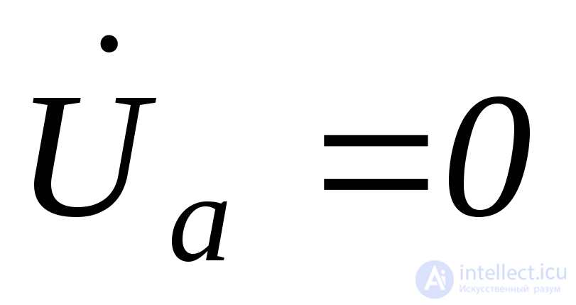 ;
;

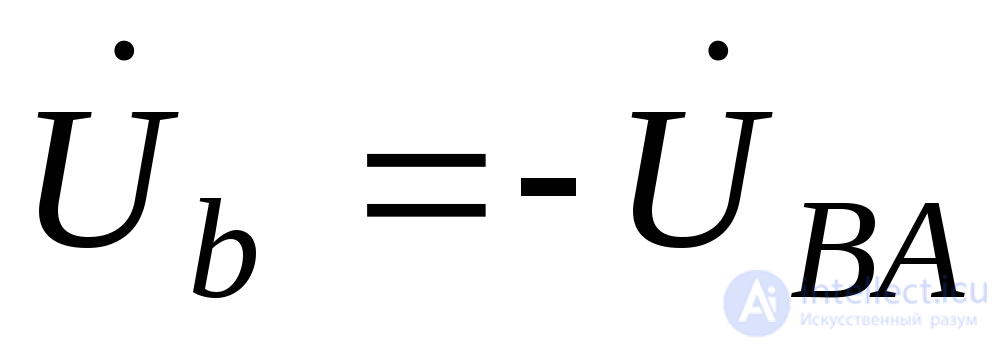 ;
;
 ;
;
i.e., the phase voltages have increased to line voltages, and accordingly, the phase currents:
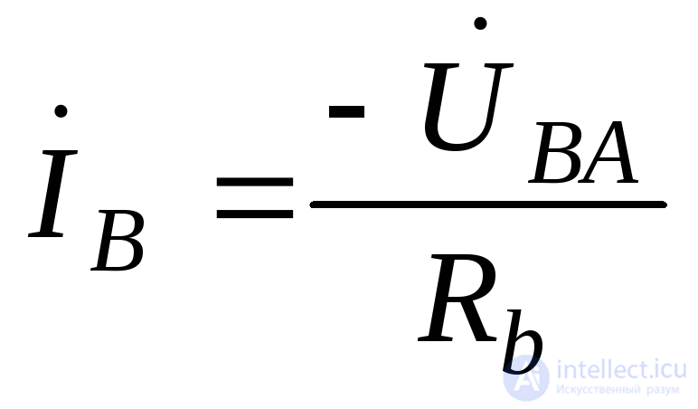 ;
;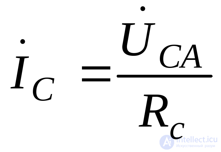 have increased by a factor of
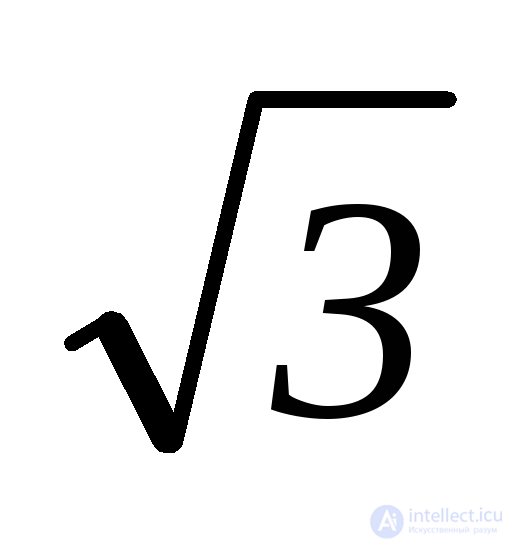 .
.
 .
.
The construction of the vector diagram is shown in Fig. 4.69.
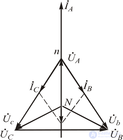
Fig.4.69. Vector diagram for a short circuit of phaseA
Problem 1.3.1 A three-phase induction motor is connected to a 380 V network in a «star» configuration. The winding parameters are as follows: Rph = 2 Ω, Xph = 8 Ω.
Required: draw the motor connection diagram; determine the phase and line currents; determine the active power consumed; construct a vector diagram of currents and voltages; consider two fault conditions – a break and a short circuit of phase A.
Solution:
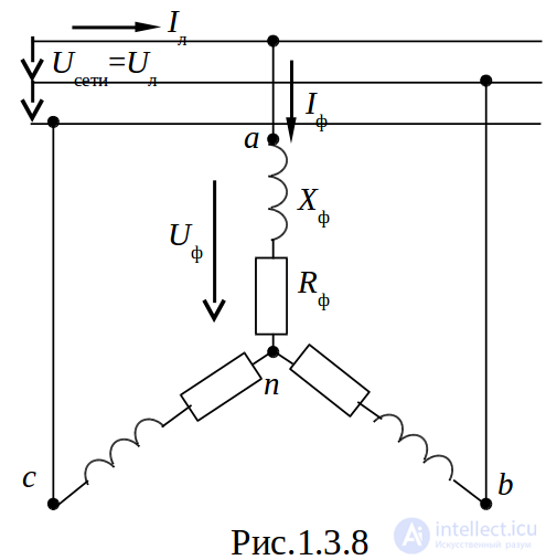
A three-phase induction motor is a symmetric resistive-inductive load, so it is connected to the network in a «star» configuration without a neutral wire. Its equivalent circuit is shown in Fig. 1.3.8
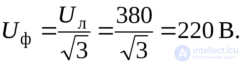
The rated network voltage is the line voltage, i.e.  , then the phase voltage
 Since the load is symmetric, the calculation can be carried out for one phase.
The total impedance of the phase

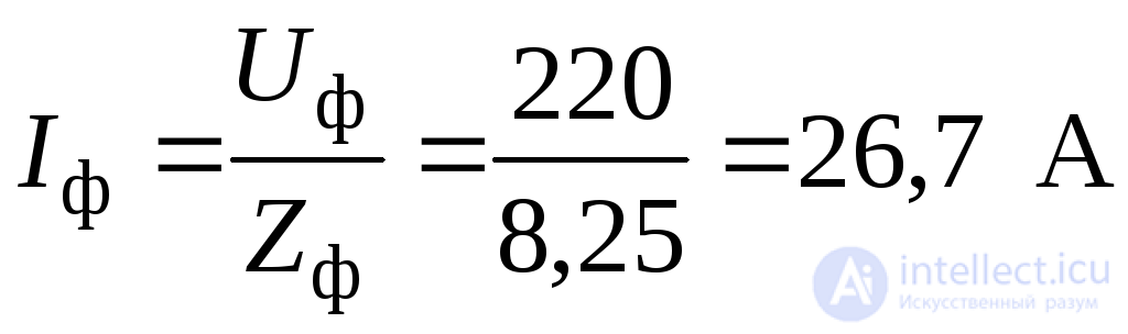
Phase current A(a)
 .
.
For a «star» configuration, the line current 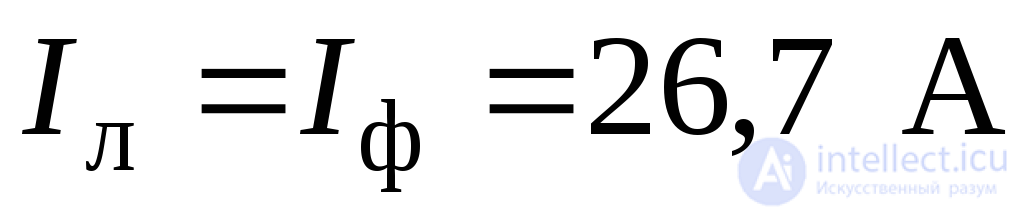 . The active power consumed
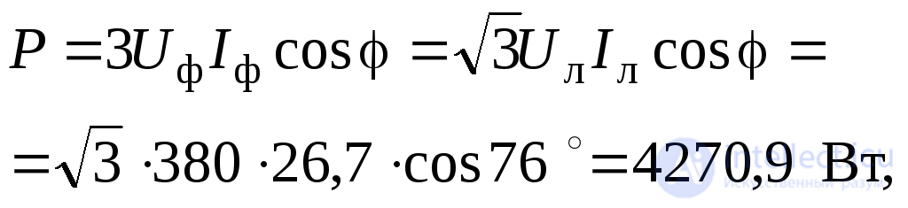
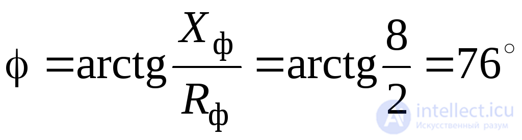
where  is the phase angle,
 .
.
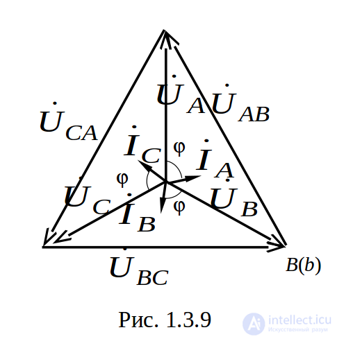
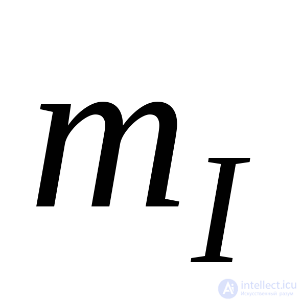
The vector diagram of currents and voltages is shown in Fig. 1.3.9. To construct the vector diagram, it is necessary to choose the scales for the voltages 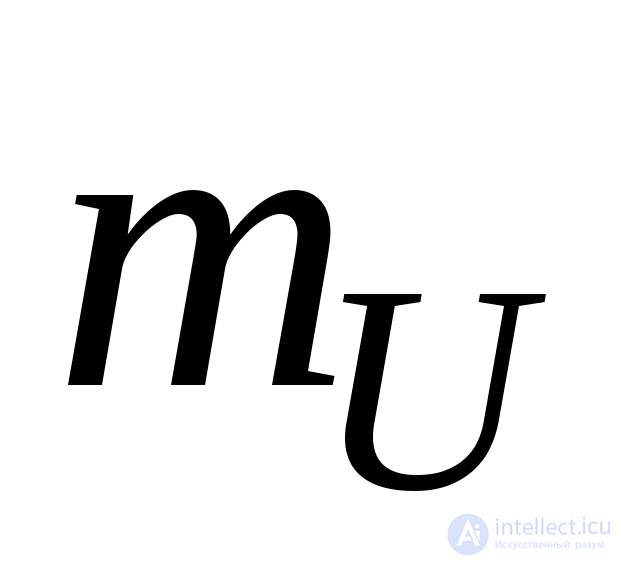 and the currents
  .
.
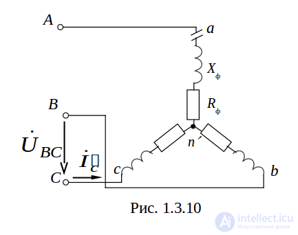
Let us consider the fault mode of operation – a break in phase A (Fig.1.3.10).
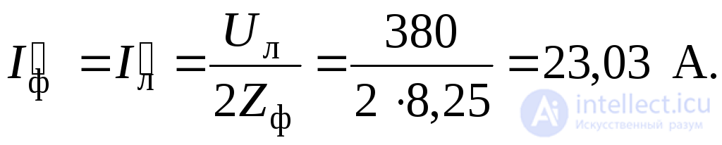
In this case, the three-phase circuit turns into a single-phase circuit 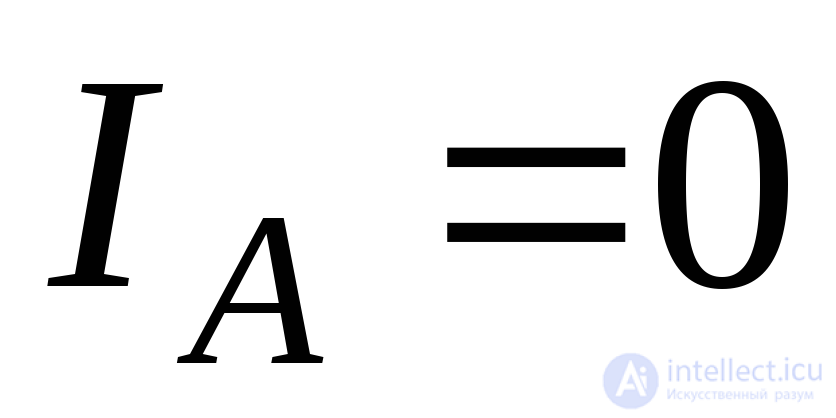 , with phases b and c being connected in series across the line voltage
 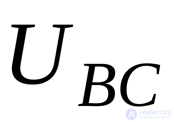 , i.e. the voltage across each of these phases is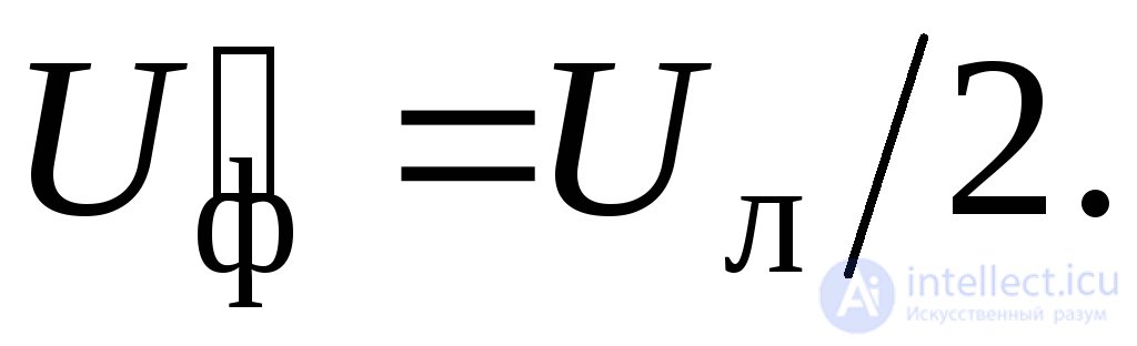
Phase and line currents
 .
.
Power consumed

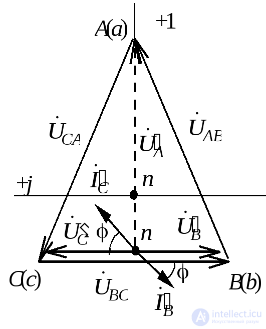
Fig. 1.3.11
As can be seen from the calculation, the power consumed decreased by almost half.
If the phase break occurs inside the motor itself (a winding break), then this winding ends up under an increased voltage 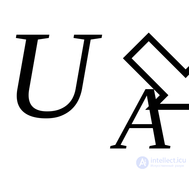 , as can be seen from the vector diagram (Fig.1.3.11). The undamaged windings are under a reduced voltage, which is not dangerous for them.
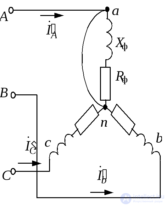
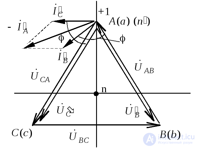
Let us consider an emergency operating mode – a short circuit of phase «a» (Fig. 1.3.12, a, b).
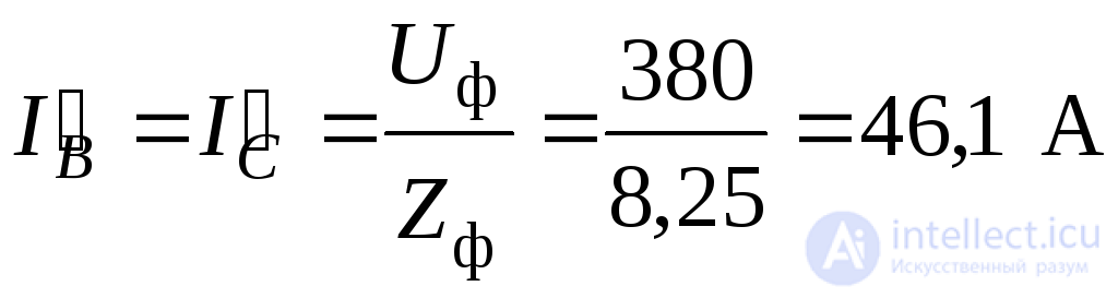
In the event of a phase short circuit, the neutral point becomes connected to the supply point A, meaning that the undamaged phases b and c will be connected to the line voltage  , as can be seen from the vector diagram.
.
a b
Fig. 1.3.12
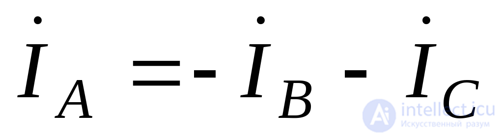
The current in phase a is equal to the geometric sum of the currents 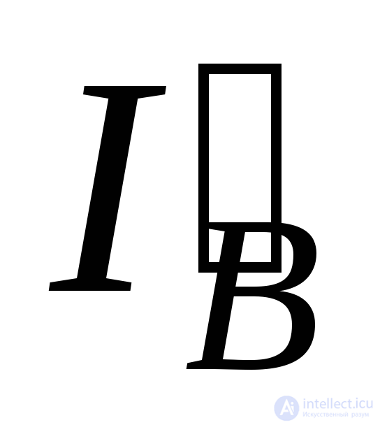 and
and 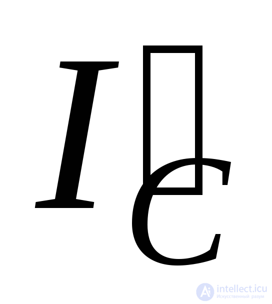 (according to the vector diagram, approximately 69 A).

Comments