
Lecture
Ethernet ( eng. Pronunciation: [iθənɛt] , literally: "ether network" ) - the most popular cable-based computer network protocol , operating at the physical and data link layer of the OSI network model . As of 2016, about 85% of all computers in the world were connected to computer networks via the Ethernet protocol.
In strict technical terms, Ethernet is a family of protocols of the IEEE 802.3 standard .
Ethernet is closely related to the TCP / IP model , since in the overwhelming majority of cases it is used to carry IP packets.
Ethernet is the most widespread protocol in modern local computer networks , and is also used to build MAN networks using Metro Ethernet [en] technology.
Ethernet was designed using CSMA / CD technology ( carrier sense multiple access with collision detection ). Although with the widespread use of network switches and full-duplex transmission media, the problem of collisions in Ethernet networks is now almost never encountered.
Ethernet networks operate at speeds of 10 Mbit / s, Fast Ethernet - at speeds of 100 Mbit / s, Gigabit Ethernet - at speeds of 1000 Mbit / s, 10 Gigabit Ethernet - at speeds of 10 Gbit / s. At the end of November 2006, a decision was made to begin development of the next version of the standard, reaching a speed of 100 Gbit / s ( 100 Gigabit Ethernet /
In technical literature, the Latin spelling Ethernet is most often retained , while in spoken language it is pronounced as "Ezernet" , although in the source language the sound is NOT voiced / ð /.
Robert Metcalfe , an employee of Xerox PARC, is considered the inventor of Ethernet . According to him, Ethernet was invented on May 22, 1973, when he finished writing a memo to PARC management about the potential of the technology .
Robert Metcalfe held a PhD degree obtained from Harvard University . While working at Xerox PARC, one of his job duties was to conduct training courses for US armed forces personnel on the world's first packet network, ARPANET . For this, Metcalfe had to frequently visit Washington , staying at a friend's apartment. Once, while at his friend's apartment, Metcalfe was leafing through a journal of proceedings from the 1970 conference of the American Federation of Information Processing Societies [en] and happened upon a paper by Norman Abramson [en] «ALOHA System [en] - Another Alternative for Computer Communications ». The paper described an innovative wireless technology for connecting computers. Although Metcalfe largely disagreed with Abramson's conclusions, the paper inspired him to work on creating a new computer network protocol.
Returning to Xerox PARC, Metcalfe, together with David Boggs [en], began theoretical work on creating a network, which resulted in a memo to company management on May 22, 1973, describing the principles of building a new system of communication between computers based on CSMA / CD technology . The report found support, which marked the beginning of putting the theory into practice. Thus, on February 11, 1973 (this date as given in the source), the first Ethernet prototype was created , which had characteristics that were fantastic for the time: a throughput of 2.94 Mb / s , a physical length of 1 kilometer, and it connected 100 computers together.
In 1975, Xerox officially announced the invention .
In 1979, Metcalfe left Xerox PARC , founded the company 3Com , and persuaded DEC , Intel , and Xerox to jointly promote Ethernet as a standard .
From the very beginning, Ethernet was based on the idea of connecting computers via a single coaxial cable , which served as the transit medium. The transmission method was somewhat similar to radio broadcasting methods (although with significant differences, for example, that it is much easier to detect a collision in a cable than over the airwaves). The shared network cable through which transmission took place was somewhat similar to the "ether", and this analogy is the origin of the name Ethernet ( eng. Net - «network» ).
Over time, from a relatively simple initial specification, Ethernet has developed into a complex network technology that is now used in most computer systems. To reduce cost and simplify management and error detection in the network, coaxial cable was subsequently replaced by point-to-point links , connected to each other by hubs / switches. Ethernet technology owes its commercial success to the emergence of a standard using "twisted-pair" cable as the transit medium.
At the physical layer, Ethernet stations communicate with each other by sending packets to one another - small blocks of data that are sent and delivered individually. Each Ethernet station has its own unique 48-bit MAC address , which is used as the destination or source for each packet. Network cards generally do not accept packets addressed to other Ethernet stations. The unique MAC address is written into the controller of each network card.
Despite major changes from 10-Mbit thick coax to 1-Gbit point-to-point fiber optic links, the various Ethernet variants remain almost identical at the lowest level from a programmer's point of view and can easily be interconnected using inexpensive equipment. This is possible because the frame format remains unchanged, despite the different network access procedures.
Ethernet is a network architecture based on a logical bus topology, with a shared transmission medium and the CSMA / CD medium access method, described by the IEEE 802.3 standard . By physical implementation, the following are distinguished:
The first element in the architecture's designation is the transmission speed in Mbit / s; the second element denotes the transmission method: Base - direct baseband transmission, Broad - use of a broadband cable with frequency-division channel multiplexing; the third element - the transmission medium (T - twisted pair, F - fiber optic) or the cable segment length in hundreds of meters (modern network adapters allow the segment length to be increased, for example for 10Base2, up to 250-300 meters).
According to the observations of the 802.3ba Task Force[22], bandwidth requirements for computing tasks and core network applications are growing at different rates, which determines the need for two corresponding standards for the next generations of Ethernet — 40 Gigabit Ethernet (or 40GbE) and 100 Gigabit Ethernet (or 100GbE). At present, servers, high-performance computing clusters, blade systems, SAN, and NAS use 1GbE and 10GbE technologies, and significant growth of the latter was observed in 2007 and 2008.
Terabit Ethernet (as the Ethernet technology with a transmission speed of 1 Tbit/s is loosely called) became known about in 2008 from a statement by Ethernet's creator Robert Metcalfe at the OFC conference[23], in which he suggested that the technology would be developed by 2015, although without expressing any real confidence, since a good number of problems would need to be solved for that. However, in his opinion, the key technology that could serve further traffic growth would be one developed in the previous decade — DWDM.
«To implement 1 Tbit/s Ethernet, many limitations need to be overcome, including 1550-nanometer lasers and modulation at 15 GHz. The future network will need new modulation schemes, as well as new fiber, new lasers - in general, everything new, — said Metcalfe. — It's also unclear what network architecture will be required to support it. Perhaps the optical networks of the future will need to use vacuum-core fiber or carbon fibers instead of silica ones. Operators will have to deploy more all-optical devices and free-space (fiberless) optics. Bob Metcalfe»[24].
Modern local computer networks almost never use technologies for which the physical medium is coaxial cable , but with the spread of video surveillance using IP cameras, this technology has gotten a new lease on life.
Also accepted as synonyms are ThickNet, Yellow, 10Base5. «Thick» Ethernet was introduced in the 1960s. This standard is obsolete and is no longer deployed in computer networks.
The classic version uses thick RG-11 coaxial cable, yellow in color, with a silver-plated center conductor and double shielding. The cable has an impedance of 50 ohms, low attenuation, and a high degree of protection from external influences. 50-ohm terminators are installed at the ends of the cable, one of which is grounded. The cable has markings in the form of dashes every 2.5 m, indicating possible connection or cut points. Cable segments can be joined with a connector. To attach a node to the cable, an MAU transceiver is installed (an active device powered by 12V), which can be connected via a T-connector or by piercing the cable ( a "vampire tap"). The transceiver is connected to the network adapter using a special drop cable (AUI Cable) up to 50 m long. The drop cable contains power lines for the transceiver and shielded twisted pairs for the receive, transmit, and collision-detection signals. Both the "yellow" cable and the drop cable have a thickness of up to 1 cm. The rigidity of the cables creates additional operational difficulties. The cost of the equipment and the complexity of installation do not favor widespread use of this architecture. Sometimes "thick" Ethernet is used to lay backbone segments when building campus networks.
Main characteristics:
Also accepted as synonyms are ThinNet, 10Base2, uses thin RG-58 coaxial cable .
Considered obsolete and very rarely used in modern computer networks. However, its use may be justified in rooms with high electromagnetic interference .
The cable has an impedance of 50 ohms, medium attenuation, and a degree of protection from external influences. 50-ohm terminators are installed at the ends of the cable, one of which is grounded. Cable segments can be joined with I- and T-connectors, and the distance between them cannot be less than 50 cm. Connecting a node always involves cutting the cable, and can be done through a T-connector or a T-shaped branch from the T-connector, which cannot exceed 10 cm. This restriction creates operational difficulties. A loss of contact anywhere along the segment (a very common fault) takes down the operation of the entire network. Problems can also occur due to T-connectors touching the metal housings of other computer connectors. The optimal way to use it is for laying the backbone network between cabling centers.
Main characteristics:
Combined use of "thick" and "thin" cable within a single segment via special adapter connectors is possible.
Improvements in network hardware, adapters in particular, made it possible to widely use twisted pair as a transmission medium. Within the Ethernet standard, the 10BaseT specification was created, which uses two unshielded UTP (Unshielded Twisted Pair) twisted pairs of category 3, 4, or 5, and 100BaseT4, based on four UTP category 5 twisted pairs or shielded twisted pair STP (Shielded Twisted Pair). Communication between network nodes requires two twisted pairs of conductors: one for transmitting, the other for receiving information. Of course, instead of two cables with one twisted pair each, a single cable with four pairs of conductors is used. Besides economy and technical advantages, this creates the possibility of moving to higher-speed network architectures without replacing the cable itself.
Physical topology - star: each network node is connected to its port on the cabling center by a cable run, which must not exceed 100 m in length. 8-pin RJ-45 connectors are attached to the ends of the cable using a special crimping tool. The most common are 8-port and 16-port cabling centers, equipped with external network adapters. Of course, one of the ports is intended for connection to a subsequent cabling center (with crossed pairs of conductors). Most cabling centers also have a connector for attaching thin coaxial cable, allowing flexible combination of Ethernet's physical topology and both of the most common cable types. The most vulnerable point of twisted-pair Ethernet is the cabling center, the failure of which paralyzes all network nodes connected to it by twisted pairs.
The main characteristics and advantages of twisted pair should be noted:
There are several Ethernet frame formats.
In addition, an Ethernet frame can contain an IEEE 802.1Q tag to identify the VLAN it is addressed to, and IEEE 802.1p to indicate priority.
Different frame types have different formats and different MTU values.
The frame begins with a preamble, which has a size of 8 bytes (64 bits) and consists of the sequence «10» repeated 31 times, and «11» at the end.
Next comes the destination address and the source address, each occupying 6 bytes. If the destination address starts with 1, this is a group transmission ( multicast ) (to everyone in the group). If the destination address consists entirely of ones ( FF: FF: FF: FF: FF: FF ) - this is a broadcast transmission. Group transmission requires configuring groups, so it is rarely used. More detail - in the article on MAC addresses .
The next field is type, or length, depending on which standard the frame belongs to. For historical reasons, if the value in the field is less than 0x600 = 1536, it is the length, and if greater - it is the type, which determines which network-layer protocol the frame should be passed to, if several network protocols are running over Ethernet. 0x800 - IPv4 . If no type is specified, then what to do with the frame is determined by the Logical link control protocol, which is another 8 bytes of headers.
Next comes the data field, less than 1500 bytes but more than 46 bytes.
If the data is less than 46 bytes, padding of the required size is added after it. This is needed so the frame can be distinguished from garbage in the channel, which appears when transmission stops due to a detected collision, and so the frame is long enough that it does not finish being transmitted before a collision would occur.
The last field - checksum . This is a 32-bit CRC . If an error is detected, the frame is discarded.
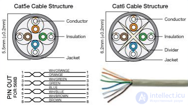
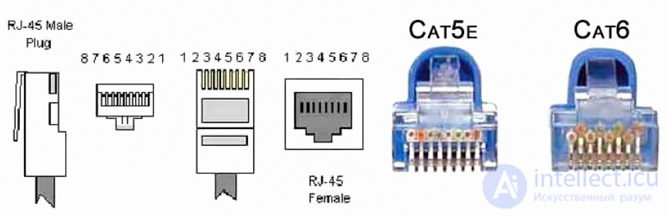
Structurally, both the cable and the connectors differ
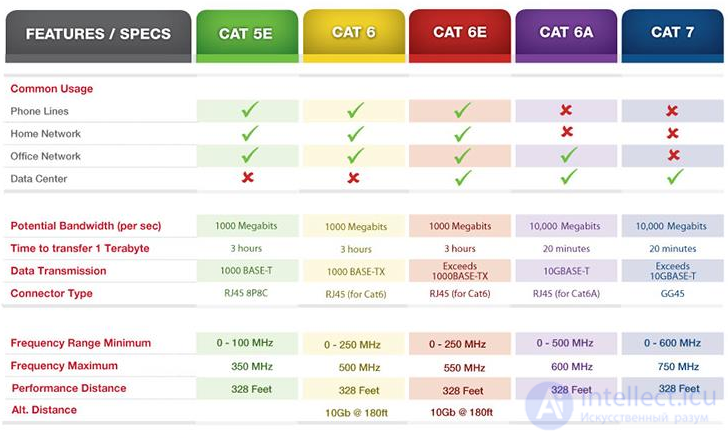
Cat5e, Cat6, and Cat6e are Gigabit Ethernet-speed cables, while Cat6A is a 10 Gigabit Ethernet cable with higher throughput. Although Cat7 has a higher throughput than Cat6A, its interface is not the standard RJ45 but rather GG45, so Cat7 is not intended for home users
Cable is manufactured from pure copper or from copper-clad aluminum. Pure copper is heavier and more expensive, but has a mass of advantages: low resistivity - which allows PoE connections with direct current to be run with minimal current loss, low brittleness, good flexibility, etc.
Cu or CCA
There are two types of conductors used in the manufacture of twisted pair - copper (Cu) and copper-clad aluminum (CCA). The cost of cable based on copper-clad aluminum is significantly lower than the cost of copper cable, however, compared to copper, copper-clad twisted pair has a number of drawbacks:
Copper cable, despite its higher price, is practically free of the drawbacks described above. Networks built on copper twisted pair last longer and require less maintenance. It is also worth remembering the greater maximum run length from the outlet to the switching device, due to the higher conductivity of copper cable.
UTP and FTP
UTP cable and FTP cable differ in construction:
Installing shielded twisted pair has a number of specific features.
For the shield to work, it must be grounded; for this, one of the ends must have a ground connection, and the equipment itself must support grounding. Only 1 end should be grounded so there are no circulating currents through the shield. To equalize the zero potential, special potential-equalization devices with large cross-section conductors exist.
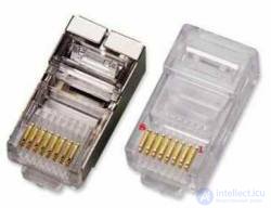
connector with and without grounding
twisted-pair outlet with grounding
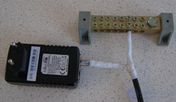
twisted-pair grounding
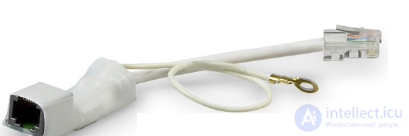
twisted-pair lightning protection
A signal wire (cable) is used to connect various elements (components) of a system. A signal wire most often consists of several pairs of polyethylene-insulated conductors, together with a PVC outer jacket. Some types of signal wires have a special shield to protect against electromagnetic interference and are called «shielded signal cables».
Shielding – is the protection of a signal wire from noise or unwanted signals.
Signal wires achieve high-quality signal transmission through their shielding and through being made as a twisted pair, in order to ensure better matching of their longitudinal impedances and their impedance "to ground". At high frequencies, common-mode interference can arise due to the difference between the wire lengths and the frequency characteristics of their impedances.
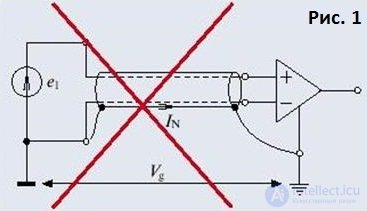
Methods of shielding signal wires take into account the paths along which interference travels.
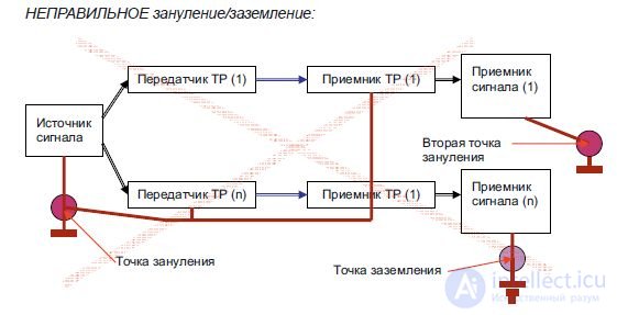
To fully eliminate the adverse effect of parasitic capacitive coupling, an electrostatic shield in the form of a conductive tube is used. In this case, the electrostatic shield should correctly be grounded only on the signal-source side. Fig. 1 shows how to incorrectly ground an electrostatic shield.
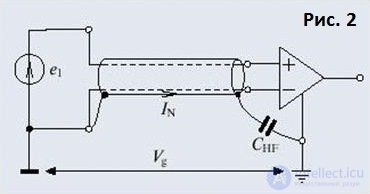
Fig. 2 shows hybrid grounding, which is the most popular method when transmitting a broadband signal from a remote source with high resistance.
Manufacturing a shield that will reliably protect against parasitic inductive coupling is much more complicated than a classic electrostatic shield. Making one requires a material with increased magnetic permeability. In addition, the thickness of such a shield must noticeably exceed the thickness of electrostatic shields.
For frequencies below 100 kHz, steel shields or shields made of permalloy (an iron-nickel alloy) can be used. For higher frequencies, shields made of copper or aluminum are suitable.
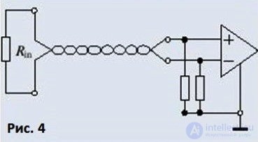
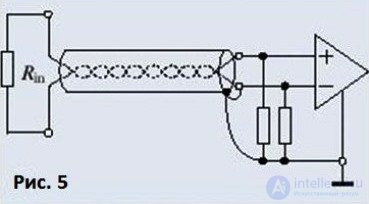
Since shielding the magnetic component of interference is difficult, particular attention must be paid to reducing the inductance of the signal cable and to selecting an appropriate receiver and transmitter circuit. Fig. 3, 4, 5, and 6 show amplifier and shield connection schemes providing different rms interference amplitudes.
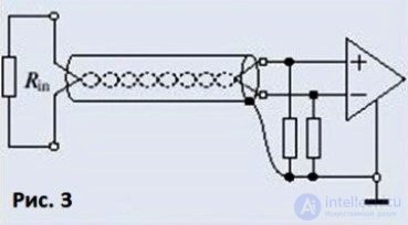
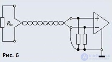
For most signal sources, temperature sensors for example, there is no protective ground, and therefore an electrostatic shield is used together with a differential-type amplifier and output resistors. The shield grounding scheme in this case – see fig. 3.
A double shield (fig. 7) is used to improve shielding quality across a wide frequency spectrum. The inner shield is grounded on one side (the signal source) to eliminate the passage of capacitive interference, while the second, outer shield is used to reduce high-frequency pickup.
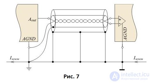
In any case, to prevent accidental contact of the shield with metal objects and the ground, it must be insulated.
In the case of a long cable, even with correct grounding, interference still passes through the shield, and so for transmitting a signal over a significant distance, or when there are strict measurement-accuracy requirements, it is better to transmit either in digital form or via a fiber-optic cable. For this, analog input modules with a digital RS-485 interface, or RS-485 fiber-optic interface converters, can be used.
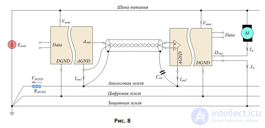
The problems described above can be radically solved using galvanic isolation (fig. 8) with separate grounding of the digital, analog, and power sections of the system. That is, the signal is transmitted between electrical circuits without any contact between them.
Without a common bonding loop, twisted-pair (TP) devices cannot function normally. An approximate diagram of a typical, correct bonding and grounding scheme is given below.
The principle of correct bonding and grounding:
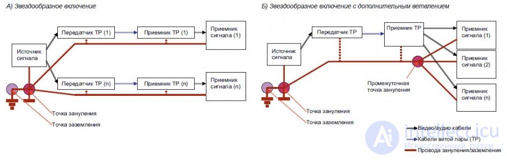
Not permitted:
The Ethernet cable color code is a standard system that defines the order of the eight wires inside an Ethernet cable. Each wire is either a solid color or has a white stripe with a color, and the color code indicates how to place them in an RJ45 connector.
Power over Ethernet transmits electricity and data over the same cable.
• Mode A uses pins 1–2 and 3–6.
• Mode B uses pins 4–5 and 7–8.
Although T568A and T568B swap color groups, the pin numbers are the same for both. PoE works with either standard, as long as both ends match.
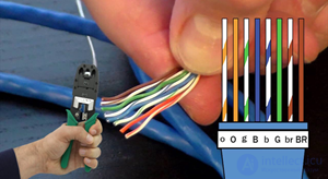
These color schemes correspond to two wiring standards:
• T568A
• T568B
Using the correct color sequence ensures that every wire connects to the correct pin. If the pinout is correct, devices can communicate properly and the cable can support its rated speed.
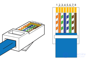
Figure 2. Each wire must land on the correct pin.
Each pair includes a solid-color wire and its corresponding striped wire. These pairs must be correctly positioned in the RJ45 connector so that the transmit and receive pins match up on both ends. Incorrect wiring can result in low speeds, a dropped connection, or complete connection failure. Using the same standard on both ends ensures consistent pin alignment and stable communication on your network.
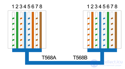
Figure 3. How the wire colors are arranged inside an RJ45 connector
Hold the RJ45 connector so the clip is facing down and the pins are facing up. T568A is often found in residential wiring and pairs well with older telephone systems.
T568A Color Order
T568B Color Order T568B is the most widely used and is found in many pre-made patch cables.
• White/orange
• Orange
• White/green
• Blue
• White/blue
• Green
• White/brown
• Brown
Both standards support the same speeds. Choose based on the infrastructure you already have.
Choose T568A if:
You should choose T568A if you are wiring a home or a small mixed-use space, if your wall outlets or patch panels already use this pattern, or if you want it to match old telephone wiring, so everything stays compatible and easy to manage.
Choose T568B if:
You should choose T568B if you are wiring an office or commercial space, if your current network cables already use this scheme, or if you want to use the most common wiring style found in standard patch cables. Do not mix T568A and T568B on the same cable run unless you are specifically planning to make a crossover cable.
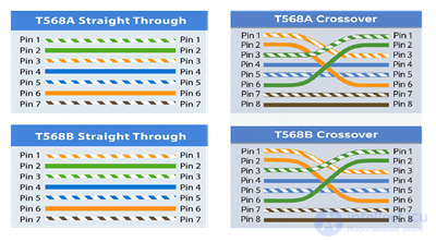
Figure 4. Comparison of straight-through and crossover wiring.
The color codes also determine the behavior of the finished Ethernet cable.
A straight-through cable uses the same wiring scheme on both ends. It is mainly used for connecting different types of devices, for example a computer to a switch, or a switch to a router. This is the standard type of Ethernet cable found in most networks.
A crossover cable uses T568A on one end and T568B on the other, with the wire pairs swapped, so that similar devices can communicate directly with each other. Modern equipment often handles this automatically via Auto MDI or MDI-X, but crossover cables are still useful for older devices and for troubleshooting.
The process of wiring T568A and T568B is identical; only the wire order differs.
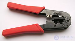
Ethernet cable, RJ45 connectors, a wire-stripping tool, a crimping tool, cutters, a cable tester.
1. Strip off about an inch of the outer jacket.
2. Separate and straighten the four twisted pairs.
3. Arrange the wires in the T568A or T568B sequence.
4. Trim them evenly.
5. Fully insert the wires into the connector with the clip facing down.
6. Crimp firmly.
7. Use the same scheme on both ends for a straight-through cable, or the opposite scheme for a crossover cable.
8. Check all eight pins with a cable tester.
| Cable Type | Description | Shielding | Best Use |
| UTP | Unshielded twisted pair | None | Homes, offices, low interference |
| STP | Shielded twisted pair | Foil | Industrial areas, near electrical power equipment |
| FTP | Foil over all pairs | Foil shield | Long-run office use |
| S/FTP | Foil on each pair plus a braided shield | Maximum protection | Data centers, high-EMI environments |
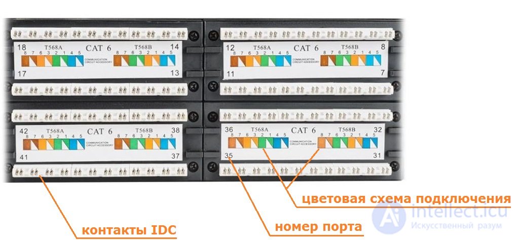
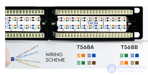
Figure 5. Patch panel with printed color guides for T568A and T568B
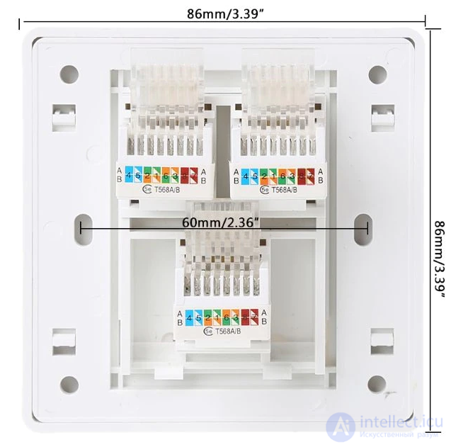
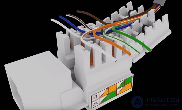
Patch panels and Keystone connectors also carry T568A and T568B markings. Most of them have colored guides showing where each conductor should be punched down.
Using the correct sequence ensures uniform pinout from the panel to the wall outlet and on to the final connector. This prevents inconsistent wiring and simplifies maintenance of large installations.
TIA/EIA-568-B — a set of three telecommunications standards published by the Telecommunications Industry Association (USA) in 2001, which replaced the obsolete TIA/EIA-568-A standard. These standards describe the construction of structured telecommunications cabling systems in buildings.
These standards are best known for the two tables T568A and T568B, which describe the connection of the conductors of "twisted pair" cable (eng. twisted pair) to the contacts of 8P8C connectors (often mistakenly called RJ-45) when setting up an Ethernet network.
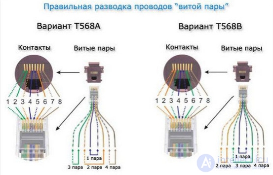
When connecting Ethernet terminal equipment (such as a computer or network printer) to switching equipment (a hub/switch/router), both ends of the cable are crimped the same way (the so-called straight-through cable). In clause 6.2.1 of the standard, table T568A is given first for horizontal connections, and, as an option, if necessary, table T568B is permitted to be used. In the US, federal law (NCS, FTR 1090-1997) allows switching only per table T568A. In practice, when building structured cabling systems and manufacturing patch cords, table T568B is more often used (including by some American manufacturers, in particular AMP).
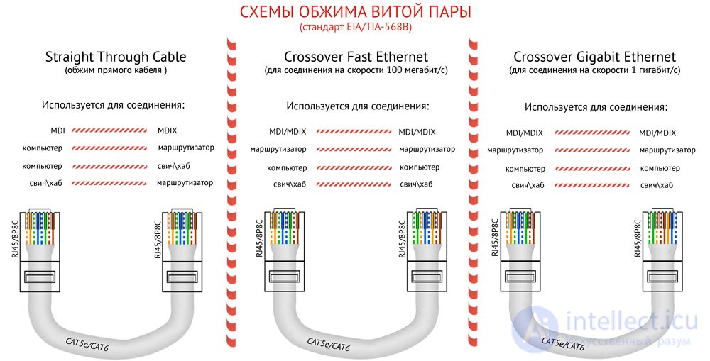
Variant per the EIA/TIA-568A standard:
and per the EIA/TIA-568B standard:
Use of a straight-through cable relies on the fact that one (and only one) of the cable's ends is connected to a switch port, and the crossing of the Rx (receive) and Tx (transmit) signal lines is done inside the port. When directly connecting two pieces of network equipment to each other (for example, two computers or two hubs), a special so-called crossover cable must be used. In such a cable, the crossing of the Rx and Tx lines is done when crimping one of the cable's ends.
Since tables T568A and T568B differ from each other precisely in that pairs 1-2 and 3-6 are swapped, to make a crossover cable for a 10BASE-T or 100BASE-T network, it is enough to crimp one end of the cable to one table, and the other end to the other.
It should be remembered that devices supporting the 1000BASE-T standard transmit data over all four pairs of the cable, with the signal on each pair transmitted simultaneously in both directions, and the frames are marked in a special way that rules out incorrect assembly by the receiving device. Therefore, either end of a cable intended for use with any 1000BASE-T devices, whether switches or nodes, can be crimped to either of the standards given.
Almost all modern Ethernet devices are able to automatically detect the type (straight-through or crossover) of the connected cable (or, what amounts to the same thing, the port type) and adapt to it. This function is called Auto-MDIX.
However, devices that do not support cable-type recognition are still common — usually these are network adapters and routers. In cases where both devices do not support Auto-MDIX and are connected via ports of the same type (two network cards or two switches), a crossover cable must be used. Nowadays this is uncommon, and to avoid confusion, all cables (patch cords and lines) are made "straight," crimped strictly to one of the T568A or T568B tables (within a building), and only where necessary is a crossover patch cord installed.
1000BASE-T devices determine the correct cable layout themselves thanks to Auto-MDIX technology (its implementation is required by the 1000BASE-T standard) .
Currently, the T568B straight-through standard is used for all cases.
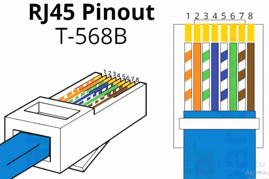
Note that the markings on the outlets visually do not match the standard, however in reality they fully correspond to it
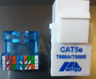
and the conductors need to be connected exactly as shown by the outlet manufacturer, while the plug is wired exactly to the standard
The bend radius of patch and equipment cables (cords) during operation must be no less than:
1. Accidentally mixing T568A and T568B
2. Leaving wires short or not fully inserted
3. Untwisting the pairs too much, which increases interference
4. Using unshielded connectors with shielded cable
5. Cutting the wires unevenly
6. Skipping cable testing


Comments