
Lecture
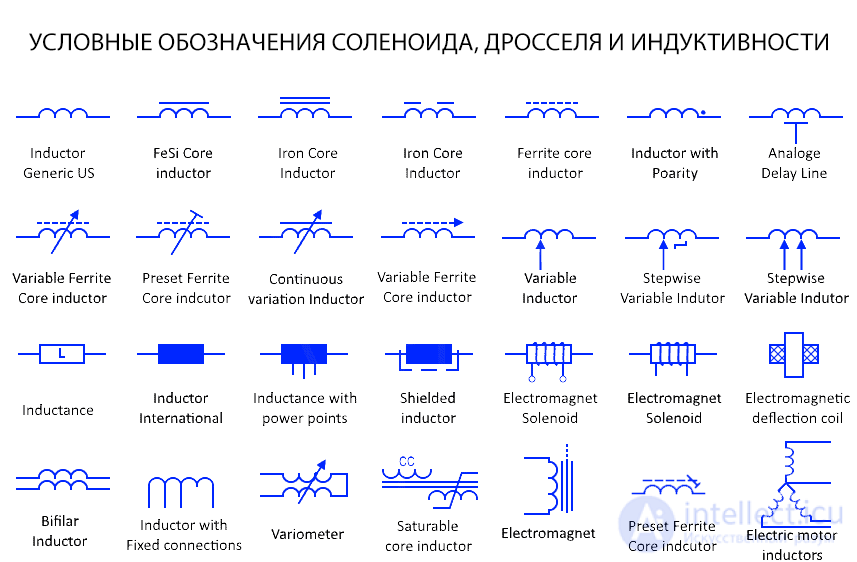
Symbols for solenoids, chokes, and inductors vary depending on their type and application. Here are the main symbols used in electrical circuit diagrams:
These symbols are used to denote inductance-based circuit elements and help distinguish induction devices such as solenoids, chokes, and coils from one another.
Universal fixed inductor
These are the symbols used to represent a general inductor whose inductance value is fixed. An inductor is also known by many names, such as a coil, choke, and so on. It stores energy within a magnetic field.
Variable inductor
This type of inductor has variable inductance. Its inductance can change while the circuit is operating, for example in radio receivers.
Step-adjustable inductor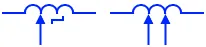
The inductance of this type of variable inductor can change in steps rather than continuously. They have a set (fixed) resistance value per step.
Inductor with polarity
Such inductors have a dot on one side of their terminal. The dot notation of the inductor indicates the direction of current entering the inductor, and it is used when connecting inductors to achieve maximum mutual inductance.
Iron core inductor
This is a type of inductor whose core is made of iron (a ferromagnetic material). The iron core increases the inductor's inductance due to its high magnetic permeability.
Ferrite core inductor
As the name suggests, these inductors have a ferrite core. Ferrite material provides high magnetic permeability along with low electrical conductivity to reduce losses within the core. They are used in high-frequency applications.
Variable ferrite core inductor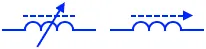
This is a type of ferrite core inductor with variable inductance. The inductance of such inductors is changed by screwing the core into or out of the coil.
Preset ferrite core inductor
Preset inductors are also variable inductors, but their inductance is adjusted during manufacturing or circuit setup. Their inductance does not change during normal circuit use.
Shielded inductor
This type of inductor core is designed to contain the magnetic field inside. Little leakage flux escapes to interfere with other nearby components. They are used in compact printed circuit boards, where space management is a critical requirement.
Electromagnet Solenoid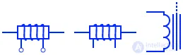
A solenoid is a cylindrical coil of conductor that creates a magnetic field when electric current passes through it. It is also known as an electromagnet.
Electromagnetic deflection coil
This type of coil is used in a CRT (cathode ray tube), where it creates a magnetic field to deflect or change the direction of the electron beam both vertically and horizontally.
Bifilar inductor
The coil of a bifilar inductor consists of two conductors running parallel to each other. The winding conductors can be antiparallel (current flowing in opposite directions) to cancel out the magnetic field each produces, or they can be parallel to double the magnetic field produced by the coil.
Variometer
A variometer is a variable inductor that provides continuous variation of inductance by moving two series-connected coils inside one another.
Saturable core inductor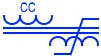
This type of inductor is specifically designed to saturate the core in order to reduce its inductance and inductive reactance. This results in a high AC throughput capacity.
Motor inductor
This is a graphical representation of a coil (winding) used inside AC machines, which converts electrical energy into mechanical energy through induction.
Analog delay line
This is a coil designed to create a time delay or phase shift in an analog signal, just as digital buffers are used to create a time delay in a digital signal.

Comments