
Lecture
Ultrasound examination (US), sonography — a non-invasive examination of the body of a human or animal using ultrasonic waves.
Elastography – is a new and modern method of ultrasound diagnostics of internal organs, which reveals minimal pathological changes in internal
Modern advances in clinical diagnostics are largely determined by the improvement of examination methods. A significant leap in this area was achieved thanks to the development and introduction into practice of fundamentally new methods of obtaining medical images. One of the most rapidly developing areas of modern medicine is ultrasound diagnostics.
An extremely valuable feature of this method is the ability to visualize the internal structure of parenchymal organs, which was impossible with traditional X-ray examination. Thanks to the high informativeness and reliability of the ultrasound method, the diagnosis of many diseases and pathologies has risen to a qualitatively new level. Currently, along with other modern examination methods, ultrasound diagnostics is used everywhere, being one of the leading diagnostic methods in many branches of clinical medicine.
The use of ultrasonic waves in medical diagnostics makes it possible to obtain information about the state of internal organs and structures. To approach the diagnostic process more competently, it is necessary to know the operating principle of an ultrasound diagnostic unit, to know the basics of the physics of ultrasound and its interaction with human body tissues. This will help avoid thoughtless use of the device, and, consequently, will improve the quality of the medical examination.
Ultrasound is sound or acoustic waves with a frequency above 20 kHz, which is higher than the maximum frequency of sound perceived by the human ear. Acoustic waves are mechanical vibrations of particles in an elastic medium, carrying energy. Such waves can exist and propagate in solids, liquids, and gases. For example, soft tissues are similar to liquid elastic media, bone formations and calculi (stones, dense formations found in the cavity organs and excretory ducts of human glands, which can be of various sizes, shapes and consistency) are similar to solid elastic media, and the lungs, intestines, and stomach contain gas formations (cavities) in their composition. For this reason, acoustic waves can propagate in all types of biological tissues.
The piezoelectric effect, thanks to which ultrasonic vibrations are obtained, was discovered in 1881 by the brothers Pierre and Jacques Curie. The Curie brothers noticed that when pressure is applied to quartz crystals or Rochelle salt, an electric charge is generated. This charge was directly proportional to the force applied to the crystal; this phenomenon was called "piezoelectricity" (from the Greek – "to press"). In addition, they demonstrated the inverse piezoelectric effect, which manifested itself when a rapidly changing electric potential was applied to the crystal, causing it to vibrate.
This discovery found its application during the First World War, when K.V. Shilovsky and P. Langevin developed sonar, used for ship navigation, determining the distance to a target, and searching for submarines. This work made a great contribution to the knowledge of generating and receiving ultrasonic waves. In 1935, Sergei Yakovlevich Sokolov constructed a direct-view ultrasonic flaw detector based on the principle of through "transillumination" of metals (flaw detection).
The study of the internal structure of objects using ultrasound, not necessarily biological ones, is called ultrasonic echoscopy. Ultrasonic echoscopy – is a set of methods and technical means for obtaining visual information about the internal structure of various objects and media by using the phenomena of reflection, scattering, and absorption of ultrasonic signals formed during the interaction of ultrasonic radiation with the object under study. The results of the research by Langevin and other physicists led to a great interest in the use of ultrasound as a therapeutic agent. Later, ultrasound began to be used in medicine for diagnostic purposes.
Attempts to use ultrasound for medical diagnostic purposes led to the emergence of one-dimensional echoencephalography in 1937. The brothers Theodore and Friedrich Dussik used a 1.5 MHz transmitter to register changes in the amplitude of energy detected while scanning the human brain. However, it was only in the early 1950s that it became possible to obtain ultrasound images of internal organs and tissues of a person. From this moment, ultrasound diagnostics began to be widely used in the diagnosis of many diseases and injuries of internal organs.
In 1950, Helmut Hertz began studying applications of ultrasound in medical research. This work brought him worldwide fame. He suggested that ultrasound could play a role in assessing the condition of the heart. In collaboration with the physician Inge Edler, he created echocardiography, a bloodless method of examining the heart.
In the 1960s, the limitation of ultrasound technology was the slow and tedious collection of images and the low image resolution caused by patient movement. Despite these constraints, ultrasound earned the respect of the medical community and quickly became a routine diagnostic method. Over the next two decades, improvements in ultrasound technology accelerated, and its use in many medical specialties became indispensable.
Ultrasound diagnostic systems use the echolocation principle of obtaining information about tissues and organs, in which signals are emitted and signals reflected from inhomogeneities of the biological medium are received, thus obtaining an acoustic image. The reflected signals that are received by the probe and used for diagnostics are called echo signals.
The main physical characteristics of an echo signal are:
Reflection – a physical phenomenon in which reflected waves are used to obtain information about tissues, i.e. waves reflected away from the waves originally emitted by the probe.
The information obtained by the probe using reflected waves is significantly influenced by such physical properties of the wave as absorption, refraction, and scattering.
Absorption – the conversion of the energy of ultrasonic waves into other forms of energy, for example, into heat, which is caused by the viscosity of the medium.
Refraction – a change in the direction of wave propagation when passing from one medium to another, which can lead to geometric distortions of the resulting image.
Scattering – multiple changes in the direction of propagation of the ultrasonic wave, caused by small inhomogeneities of the biological medium, which, in turn, leads to numerous reflections and refractions.
All of the above characteristics are the cause of the attenuation of the echo signal in biological tissues, which characterizes the decrease in the energy of ultrasonic waves as they propagate.
An ultrasound scanner - is technologically complex equipment, each unit of the ultrasound machine is responsible for certain functions; if one of the units breaks down, the ultrasound machine fails completely or partially – in either case, repair of the ultrasound scanner is required.
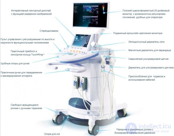
The monitor of an ultrasound machine must have good resolution and have a diagonal size convenient for the user for full-fledged display of the object under examination.
The control panel, as a rule, consists of a button part/keyboard and a trackball, and modern models of ultrasound machines are equipped with touch displays. It is necessary to handle the keyboard carefully and prevent liquid from getting on it, since in this case the keyboard will need to be replaced. For proper operation, the trackball needs to be cleaned regularly and in a timely manner.
The hard disk drive is located inside the equipment. If the equipment is new, users generally do not experience problems with the hard disk drive, but if the equipment has been used for more than 3 years, the hard disk drive wears out and there is a possibility of the hard disk drive failing. We recommend making periodic disk copies in order not to lose data.
Ultrasound probes for the ultrasound scanner are acquired depending on the type of examinations performed on this machine. As a rule, a linear, abdominal, and cavity probe always come as part of the standard set of an ultrasound machine; other probes are acquired if the type of examination requires it.
The printer of the ultrasound scanner is necessary for printing examination results; we recommend purchasing original paper recommended by the printer manufacturer, otherwise the printer head overheats and the printer fails.
The power supply unit is responsible for converting the voltage that goes to the unit with electronic boards. Therefore, the power supply unit often fails, since components burn out. In order to protect the power supply unit and avoid the need for repair of the ultrasound power supply unit, we recommend using a UPS (uninterruptible power supply) with double conversion.
The unit consisting of several boards. This unit is responsible for converting the ultrasonic beam into an image, the correct operation of all functions, connecting the ultrasound probes, generating calculations, and many other functions. This is the heart of the ultrasound machine. Our engineers deal with this unit when repairing the ultrasound scanner.
The block diagram of the ultrasound scanning device is shown in fig. 1.1.1.
An ultrasound machine includes the following main units:
Pulse generator – a multichannel device that transmits short electrical pulses to the beamformer on each of the channels. The main tasks performed by the pulse generator are:
· generating pulses of the shortest possible duration, since the shorter the pulse, the better the longitudinal resolution;
· ensuring the pulse amplitude at the required level, but not exceeding what is permissible from the point of view of patient safety;
· performing a time shift between pulses. Some time is required to form a beam with the required focus. In addition, during the delay between pulses, a signal is received from the tissues.
Beamformer – a multichannel device connected to the probe by a multicore cable in accordance with the total number of transducer elements. Its main function is to ensure the required shape of the ultrasonic beam on transmission and reception.
In the switch, the total number of piezotransducer channels is changed to a number equal to the number of receiver and transmitter channels.
On the probe head are located the piezoelements, which convert electrical energy into ultrasonic wave energy.
Scan mode control. Control of the operation of all elements is performed by means of a program developed individually for each device. Depending on the complexity of the device, this involves control of the scan converter functions, processing of measurement results, and changing the pulse frequency depending on the selected probe type.
The receiver receives echo signals from the beamformer, amplifies them, subjects them to certain conversions, sums the signals from all channels, and delivers the summed signal to the scan converter
The scan converter – is a digital device used to convert the information obtained from the receiver output into a form suitable for display on the device's monitor.
From the scan converter output, information for display is fed to a digital memory device. Recording occurs at the same rate at which scanning takes place. On the output, the information is read out at the rate required to obtain an image in the television standard.
The output devices are a printer for obtaining a hard copy of the acquired image and a monitor.
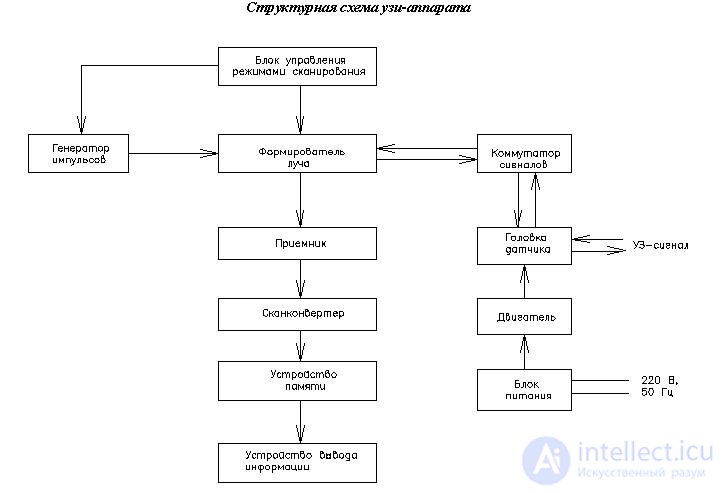
Fig. 1.1.1 Block diagram of an ultrasonic scanning device
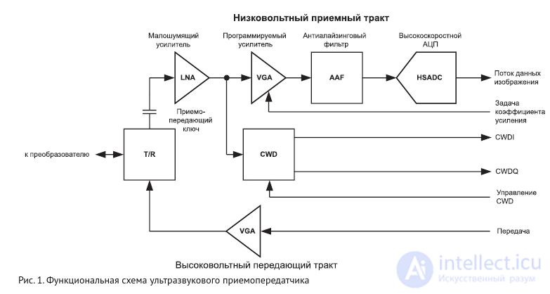
A typical circuit of an ultrasonic transceiver is shown in Figure 1. To obtain an ultrasonic image, the high-voltage transmitter generates synchronized high-voltage pulses. These pulses excite the ultrasonic transducer (piezoelement), which generates directed sound signals. The signals propagate and, reflecting off inhomogeneities in the patient's body, are received by the same transducer. They then pass into the receive path of the transceiver.
The receiver contains several functional blocks: a transmit/receive switch (T/R), a low-noise amplifier (LNA), a variable-gain amplifier (VGA), an anti-alias filter (AAF), and an analog-to-digital converter (ADC). To protect against high-voltage pulses, the low-noise amplifier is connected to the transducer through the transmit/receive switch. The LNA gain is fixed to reduce sensitivity to noise. The variable-gain amplifier (VGA) is used to compensate for ultrasound attenuation in the human body. This allows the input signal to be matched to the dynamic range of the ADC. The presence of the anti-alias filter (AAF) in the receive path is necessary to remove high-frequency noise components that fall outside the boundaries of the analyzed frequency spectrum. The amplified and digitized samples are processed by a digital beamforming system to obtain a directed and formed signal. The resulting signal is used to create 2D images or to obtain additional information about spectral shift when working with Doppler signals in pulsed mode.
The receiver also contains a separate beamformer block for working with Doppler signals in continuous-wave mode (continuous-wave Doppler, CWD). The CWD block is located immediately after the low-noise amplifier (LNA). This is because the CWD operating mode is very demanding on the dynamic range of the input signal, which exceeds the capabilities of the VGA/ADC blocks. To obtain the required output data stream, it is necessary to mix the input signal with the frequency signal of local oscillators and sum the resulting results. For this reason, the CWD block must include high-dynamic-range mixers and programmable oscillators.
It is quite obvious that transceivers possess broad functionality, and fitting 128 such devices into the form factor of a personal computer is not a simple task. Electronics manufacturers respond to this by increasing the level of integration. Currently, it is not difficult to find chips with eight receivers, including LNA, VGA, AAF, and ADC, and fitting into a package measuring 10×10 mm. High-voltage transmitters are also produced in four- and eight-channel versions with a package size of 10×10 mm. This increase in integration is extremely important. It has played a key role in the emergence of the modern generation of portable systems. However, looking ahead, it should be said that this is not the limit of the capabilities of integrated technologies.
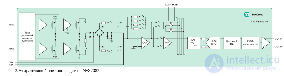
The MAX2082 chip contains eight transceivers (Figure 2), and represents a striking example of the most modern achievements in the field of highly integrated ultrasound solutions. The chip includes a complete receive path, a transmit/receive switch, decoupling capacitors, and a three-level pulse sensor. All of this is housed in a package measuring 10×23 mm. Such a transceiver saves occupied area, reduces development time, and lowers the overall system cost.
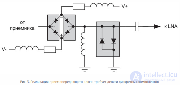
The savings in occupied area when using such chips can be significant. Even the use of just one integrated transmit/receive switch alone saves a lot of space. Let us consider a typical and most common implementation circuit for such a switch (Figure 3). As can be seen from the figure, it requires nine discrete components. This means that in a device with one hundred twenty-eight channels, the number of discrete components needed to create just the transmit/receive switches will exceed 1000!

Fig. 4. 128-channel board based on eight-channel transceivers
Figure 4 shows a printed circuit board (PCB) of a 128-channel transceiver based on the MAX2082. The board has an area of less than 10 square inches, which is half the area obtained when using separate chips for eight-channel receivers, eight-channel transmitters, and discrete T/R switches.
Organizing power supply for highly integrated devices is a complex task. First, most ultrasound devices are portable and must operate on battery power without recharging for at least an hour. Second, heat dissipation is also a major problem. The density of component placement on the PCB is quite high, and the distance between them is small, which leads to a lack of space for airflow. It is important to note that ultrasonic transceivers contribute significantly to the overall power consumption of the system, which requires increased attention during design.
Over the past ten years, the power consumption of ultrasonic receivers has been reduced by half. Now it is not a problem to find an integrated receiver with LNA, VGA, AAF, ADC, whose consumption is less than 150 mW per channel. In addition, the new generation of receivers has a flexible power management system that allows the user to find a compromise between consumption and performance, and to use sleep modes with fast wake-up to save energy in inactive mode.
There are other prospects for improving the properties of transceivers. For example, a single T/R switch consumes up to 80 mW. This is due to the need for bias currents to flow through the diodes to reduce their resistance and improve noise characteristics. And this power is equal to the consumption of all the transceiver's components combined! The newest integrated T/R switches, such as the MAX2082, have better noise characteristics while consuming only 15 mW.
Increasing the level of integration and reducing power consumption are the main tasks in creating ultrasound systems. However, it is not immediately obvious that these problems are directly related to equipment miniaturization.
Reducing the noise level in the operating frequency range
Ultrasound systems are extremely sensitive to conducted and radio interference occurring at frequencies of 2…15 MHz. The input sensitivity of each channel can be as low as 1 nV/Hz. In 128-channel devices, the gain of unwanted signals can reach 21 dB depending on the amount of delay between the operation of channels when forming the working stream. As a result, even noise with a low density of 0.09 nV/√Hz (in the operating frequency range) is clearly visible and manifests itself as artifacts in the resulting image. Such artifacts are well known and are often called "flickering lights"; they resemble bright flashes in those places of the image for which the highest gain is set. There are a large number of sources of conducted and radio interference that cause such noise.
Developers of ultrasound circuits need to expend a great deal of effort to form ground loops, as well as to physically enclose and shield sensitive analog elements from noisy digital circuits. Unfortunately, engineers creating portable ultrasound devices in most cases do not have the luxury of physically separating sensitive and noisy circuits, and shielding is difficult due to limited space and heat dissipation problems. As a result, the presence of noise in the operating frequency range is practically unavoidable, especially in those devices where single-board computers, which are necessary for processing the acquired data and displaying it on screen, are located in close proximity. Thus, maximum attention must be paid to grounding and shielding issues at the earliest stages of design. Attempts to modify highly integrated devices at later stages, when prototypes are being created, can prove to be extremely difficult and costly.
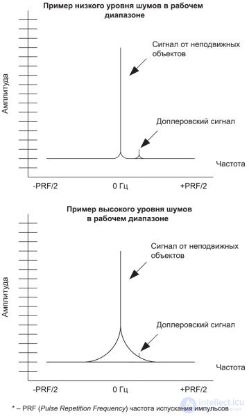
Fig. 5. Examples of the effect of noise level on the analysis of Doppler signals
In a number of cases, acoustic noise can be the source of even more complex problems. When performing ultrasound examination, blood movement is determined by the small Doppler shift of reflected and received waves. Any low-frequency modulation of the transmitted or received signal from stationary objects causes noise, which can drown out useful signals or even form false peaks in the working frequency spectrum (Figure 5). When working with Doppler signals in pulsed mode, the signal-to-noise ratio in the 1 kHz offset range must be greater than 140 dB/Hz relative to the carrier. For continuous-wave mode (CWD), the requirements are even stricter – at least 155 dB/Hz relative to the carrier.
There are a large number of sources of low-frequency noise, but the most significant and common among them are low-frequency switching power supplies. It is the interference they create that causes the most harm when using the Doppler effect. Their noise can cause jitter in the frequency of the receiver and transmitter oscillators, which, in turn, will lead to a narrowing of the dynamic range or to the appearance of unwanted peaks in the spectrum. These same noises can also affect the VGA gain control circuit, which will lead to additional modulation of the received signal and, consequently, to obscuring of the useful Doppler signal.
An effective way to reduce audio noise levels caused by power supplies remains active power consumption management. In traditional large-scale ultrasound systems, this is achieved by using multiple separate, inefficient linear regulators distributed throughout the system. Obviously, this approach is not available in portable devices.
As a result, developers have to use a distributed system of switching regulators to improve efficiency. Unfortunately, when switching, this type of regulator creates significant conducted and radiated interference, which is difficult to control even with high-quality layout and filtering. The Doppler signal spectrum is sensitive to such noise. Usually it leads to the appearance of additional tones on the frequency response. The only way to combat this phenomenon is to synchronize the switching power supplies with the system's operating frequency. In this case, the resulting noise is easier to move out of the operating range. Thus, maximum care must be taken when using switching regulators in such devices in order to minimize power consumption and avoid negative effects.
Performance testing may include the following work;
1. PSU failure
In most cases, such faults appear due to voltage problems. Mains voltage surges, power outages - all of this can cause significant damage to the scanner. To avoid costly repairs, we recommend using a double-conversion UPS (uninterruptible power supply), which significantly extends the life of the power supply. This problem is also observed in equipment that has already been in use for a long time, since the components of the power supply also have their own service life.
Symptoms - the ultrasound scanner does not power on or spontaneously reboots.
Solution - replacement of the power supply or repair of the power supply at the component level
Component-level repair of power supplies - this is replacement of components with new ones, which is many times more complex than unit replacement, but this type of repair is cheaper and faster.
As a rule, the problem is related to the age of the ultrasound scanner, the hard drive wears out and fails, so do not forget to periodically back up your system data.
Many manufacturers already have this feature built into the system, but even if it is not available, you can save data and make a full backup of the entire archive using external systems.
The main thing is to entrust this to a specialist so as not to accidentally damage the disk structure or the data itself during the saving process.
Symptoms - the ultrasound machine does not fully boot, periodically freezes
Solution - hard drive replacement.
If peripheral devices break, this is not a reason to replace them - very often they can be successfully restored.
read more here
DESIGN PRINCIPLE AND MAIN TYPES OF LCD MONITOR FAULTS AND METHODS OF THEIR REPAIR
monitor repair, monitor diagnostics
printer repair, printer diagnostics
[[b3290]]
There are more than enough problems with ultrasound probes, ranging from image defects to physical defects of the probe itself. In this article we have described the main problems we encounter when repairing ultrasound probes
Problems usually occur due to lack of maintenance.
Solution - cleaning or replacement.
read more here
The problem may be related to failure of the piezoelements or may arise due to cable problems. In this case, diagnostics of the ultrasound probe is required.
But before sending the probe for repair, it is necessary to rule out the possibility that the ripples and stripes appear due to electromagnetic interference. External interference and noise can be created by X-ray or MRI equipment operating in a neighboring room, welding machines, telecommunication towers located nearby, and other sources of radiation.
Possible cause - loss of seal, air ingress into the probe.
Solution - reassembly and repair of the 3D probe
The problem occurs over time or with improper handling of the ultrasound probe.
Solution - replacement of the acoustic lens.
Check the probe's functionality in 2D mode; if the probe works, then the 3D mechanism has probably failed.
Solution - repair of the 3D mechanism
Each type of probe may have specific problems
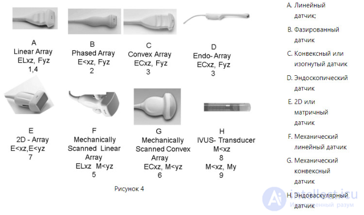
The probe is identical in structure to the convex one, the only difference being that the microconvex probe is smaller in size.
Main problems with cavity ultrasound probes:
With improper handling or over time, the acoustic lens of the ultrasound probe may delaminate or wear through. It is not permitted to work with such a probe; replacement of the acoustic lens is required.
Piezoelements can be damaged by impact, or they may fail when the probe is used with a damaged acoustic lens
Often, through carelessness, the ultrasound machine runs over the cable, which causes irreversible consequences. In this case, cable replacement is required.
Due to impacts or prolonged use, the fragile 3D mechanism fails. In this case, it is not necessary to buy a new ultrasound probe - our service department can easily restore it.

Comments