
Lecture
Cable lines (CL) are subjected to a variety of tests immediately after construction and during operation, which are used to identify weakened spots or defects in the insulation and protective sheaths of the cables, in the joint and termination fittings, and in other elements of the cable lines. The causes of such weakened spots vary. They may arise during manufacture of the cable and fittings at the factory due to design shortcomings of the cable and fittings, during careless laying of cable lines, or due to poor-quality installation work. Weakened spots are revealed during operation of the CL, since over time the insulation of the cables ages and their metal sheaths corrode. Cable lines laid in an earth trench, despite additional protection in the form of brick covering and systematic monitoring of the route condition, are subject to external mechanical damage that can occur during the laying and repair of other underground structures crossing the CL route. With the exception of direct mechanical damage, weakened spots and defects in CL are of a hidden nature. If not detected in time by testing, they can develop, at one rate or another, under the influence of the operating voltage. In this case, complete destruction of CL elements at the weakened spot is possible, with the line transitioning into a short-circuit mode, which entails disruption of power supply to consumers. The complete list of CL tests, depending on voltage and purpose, is regulated by the "Electrical Equipment Testing Standards."
To test cable lines with elevated voltage, rectified voltage from mobile test units is used. The parameters of the test units depend on the leakage current and insulation of the CL, whereas when using elevated alternating voltage, the parameters of the units are determined by the capacitance of the lines, which is significant for CL. In this case, rectified voltage, compared to alternating voltage of the same magnitude, has a small effect on undamaged cable line insulation. Testing with rectified voltage does not reveal all weakened spots in CL insulation. In particular, the following are not detected: electrical aging of the insulation; drying out of the insulation due to migration or drainage of the impregnating compound; drying of the insulation due to a heavy thermal operating regime of the cable lines. Elevated-voltage tests are destructive, since when the test voltage is applied, the CL insulation at the defect site is brought to complete breakdown. After breakdown, repair of the line to one degree or another is required. For lines with voltage up to 1 kV, instead of testing with elevated voltage, it is permissible to check them with a 2500 V megohmmeter.
When testing with elevated voltage, it is necessary to take into account the nature of changes in leakage currents, which for CL with satisfactory insulation are generally quite stable. For cables with paper insulation rated up to 10 kV, the leakage current is within 300 μA; for 35 kV cables, about 800 μA. In this case, the absolute value of the leakage current is not a rejection criterion. Before and after testing the lines with elevated voltage, the line insulation resistance is measured using a megohmmeter. In this case, the insulation resistance of CL up to 1 kV must not be lower than 0.5 MΩ. For lines of other voltages, the insulation resistance is not standardized. Checking with a megohmmeter also makes it possible to detect serious CL damage, in particular, grounding and conductor breaks, short circuits between conductors, and so on. Preventive tests (PT) are divided into scheduled and unscheduled. Preventive tests of cable lines rated 6-35 kV must be carried out at least once every three years. Lines that, based on operating experience, have an insufficiently satisfactory insulation condition or operate in unfavorable conditions (frequent earthworks along the line route, active corrosion, etc.) are recommended to be subjected to more frequent testing. Extraordinary tests are assigned after earthworks are carried out along the CL route, after its relaying or major overhaul, in the presence of ground subsidence or erosion along the route, and so on. Preventive tests of CL can be carried out by two methods: with the lines taken out of service and fully disconnected for the duration of the test; or without taking the lines out of service, by applying test voltage to a section of the network that is under operating voltage and under normal load (testing "under load").
After a CL breakdown due to a failure or as a result of testing, with the exception of direct mechanical damage, it becomes necessary to determine the location of the line fault. Nowadays there are advanced methods by which the fault location can, as a rule, be established with sufficient accuracy and in a limited time. Each method has its own area of application, which is determined by the nature of the CL damage and, among other things, by the transition resistance arising at the fault location. In this regard, before determining the fault location, it is necessary to determine the nature of the damage, and also, if necessary, to burn through the cable in order to reduce the transition resistance at the insulation fault location to the required level. CL damage is of various types: insulation damage with one conductor shorted to ground; insulation damage with two or three conductors shorted to ground, or two or three conductors shorted to each other at one or several points; break of one, two, or three conductors with or without grounding of the conductors; self-healing ("floating") insulation breakdown; complex faults containing the above types of damage. The most common case is damage between the conductor and the cable sheath, i.e., single-phase faults, especially for cables with conductors in individual sheaths.
All measurements on CL are carried out with them fully disconnected and with all necessary safety measures observed. As a rule, the nature of the damage is determined using a 2500 V megohmmeter, which measures the insulation resistance of each conductor relative to ground and the insulation resistance between conductors. The continuity of the conductors is checked from both ends of the line by alternately installing a short-circuit jumper at the ends of the line. When determining the nature of a complex fault, cable line inhomogeneity locators are used, and if necessary, the nature of the fault is clarified by successive testing of each conductor's insulation with rectified voltage relative to the sheath and between conductors.
In accordance with established practice, the fault location is determined in two steps: first, the fault zone of the cable line is determined, then the fault location is refined within that zone. At the first stage, the fault location is determined from the end of the line; at the second stage, directly along the line route. Accordingly, the methods are divided into distance-based (relative) and topographic (absolute) methods. Distance-based methods include: the pulse method, the oscillatory discharge method, and the bridge method, while topographic methods include the induction method, the acoustic method, and the surface loop (overlay frame) method. In the pulse method, a so-called probing electrical pulse is sent into the CL, and the time between the moment the probing pulse is sent and the moment the pulse reflected from the fault location arrives is measured. This takes into account that the propagation velocity of electromagnetic oscillations in CL with paper insulation is within 160 m/μs. The instrument is connected to one end of the line (the connection scheme is chosen depending on the nature of the damage). The pulse method can be applied to CL of any design for single-phase and multi-phase faults of a stable nature and for complex faults.
The oscillatory discharge method is based on measuring the period (half-period) of natural electrical oscillations that arise in the CL at the moment of its breakdown, i.e., during the discharge of an electric arc at the fault location. To determine the fault location using this method, the line must be brought to breakdown at the moment of measurement, which is achieved by applying elevated voltage (below the test voltage) to the line. The method is intended for determining the fault location of cable lines in the presence of a "floating" (self-healing) breakdown, or in cases where electrical discharges are observed at the fault location. A "floating" breakdown is characterized by successive breakdowns with varying time intervals under the influence of elevated voltage. When the voltage is reduced, the breakdowns stop. In some cases, the damaged line begins to withstand a higher voltage, up to the test voltage, i.e., the line insulation temporarily recovers. This is observed mainly in joints. In the process of determining the fault location, the unit's voltage is raised to the breakdown voltage, and at the moment of breakdown the instrument takes a measurement. When determining the location of a single-phase fault, the intact conductors of the CL must be insulated. In the event of a fault between conductors, the test unit's voltage is applied to one conductor, while the other two are grounded through a resistance of more than 1000 Ω.
The bridge method involves the use of DC or AC measuring bridges. To measure the distance to the fault location, a bridge circuit is assembled from adjustable resistors of the measuring bridge, the damaged and healthy conductors, short-circuited at the opposite end of the line. When determining the fault location, balance of the bridge is achieved by adjusting R1 and R2. The distance to the fault location is determined as

where L - length of the line;
R1 and R2 - resistance of the resistors connected to the damaged and undamaged conductors, respectively.
When using the bridge method, it is necessary to have one undamaged conductor, or a conductor with a transition resistance not less than 100 times the transition resistance of the other conductors. The method reliably determines single-phase and multi-phase faults of a stable nature.
In the event of conductor breaks, the fault location is determined by measuring the capacitance of the line using an AC bridge. As a rule, a universal cable bridge is used, which permits measurement on both direct and alternating current.
The induction method belongs to the topographic methods and is based on the principle of listening from the ground surface to the sound created by electromagnetic oscillations when audio-frequency current (800 - 1200 Hz) passes through the cores of a cable line (CL). For this purpose, an audio-frequency generator is connected to two cores of the cable line. A special receiving frame with an amplifier (cable locator) and telephone headphones are used to listen to the sound. As the operator moves along the route with the cable locator, the sound in the headphones will periodically change due to the presence of core twisting. In addition, the sound will be amplified over a joint sleeve, and will change depending on changes in the laying depth of the line, the presence of pipes, etc. Only over the point of damage will a sharp increase in sound be noted, followed by its attenuation at a distance of 0.5 - 1.0 m from the damage. The induction method is used to determine two- and three-phase faults of a stable nature with a transition resistance value of no more than 20 - 25 Ohms. Audio-frequency generators and cable locators of various circuit and design configurations are used. In order to increase the sensitivity of the method and eliminate industrial interference (adjacent cables, electrified transport, etc.), the generator frequency is increased to 10 kHz, cable locators with highly selective antennas are used, and tuned frames are employed. The induction method is widely used to determine the route of a cable and the depth of its laying in a soil trench. For this purpose, the first terminal of the generator is connected to a core, its opposite end and the second terminal of the generator are grounded. The generator current, depending on the magnitude of interference and the depth of the cable laying, is set up to 15 - 20 A. With the horizontal position of the cable locator's receiving frame, the maximum sound in the headphones will correspond to the position over the cable. With the vertical position of the frame over the cable, the sound will disappear; as the frame is moved to one side or the other from the cable, the sound first increases and then slowly decreases. As a result of listening to the sound over the route, its precise position is established. To determine the laying depth of the cable, the cable locator's receiving frame is set at an angle of 45° to the vertical plane passing through the cable. The frame is moved away from the line of the cable's location until the sound in the headphones disappears. The distance between the route line and the position of the frame will correspond to the laying depth of the cable. The method is also used to determine the position of joint sleeves on the route. In this case, the generator is connected according to a two-wire supply scheme, i.e. the generator terminals are connected to two cores of the line, and the latter are short-circuited at the other end. A sharp increase in sound will be heard over the sleeves. The surface (clamp-on) frame method is a variant of the induction method. In this case, instead of the receiving frame, a so-called clamp-on frame is connected to the cable locator, made in the form of a metal collar inside which a measuring coil is located. The clamp-on frame is rotated by the operator around the damaged cable with the audio-frequency generator switched on. The sound in the headphones will change twice before reaching the point of damage, reaching a maximum and a minimum; over the point of damage a monotonous sound will be heard in the headphones. The clamp-on frame method is applied to openly laid cable lines, in the case of a short circuit of one core to the sheath, and in the case of insulation damage of two or three cores with high transition resistance. When the method is applied to lines laid in the ground, the route is exposed by means of test pits.
The acoustic method is based on listening over the point of damage for sound vibrations arising at the damage location due to a spark discharge from electrical pulses sent into the cable line. A test set serves as the source of the pulses. The circuit for determining the fault location depends on the type of CL fault. If a "self-healing" (intermittent) breakdown has occurred, the source of pulses is a test set whose voltage is raised until breakdown occurs at the point of damage. In the case of stable short circuits, a test set, a spark gap, and a storage (charging) capacitance or the capacitance of undamaged cores are used to form the pulse at the point of damage. In this case, a discharge occurs simultaneously with the spark gap at the point of CL damage. In the process of determining the fault location, the sound of the discharge from periodically sent pulses is listened to at the point of damage by the operator using a stethoscope or a cable locator with a piezoelectric sensor, which converts mechanical vibrations arising in the soil during the pulse discharge into electrical signals. The maximum sound corresponds to the point of damage. The method is used for "self-healing" breakdowns, single- and multi-phase faults of a stable nature (but not metallic short circuits), and for core breaks with grounding at the point of damage. Modern cable locators are acoustic-induction devices and can be used for both acoustic and induction measurement methods. Certain difficulties arising in remote and topographic methods of fault location determination occur with single-phase ground faults. In particular, the pulse method gives reliable results only with a low value of transition resistance at the point of damage. For this reason, new instruments have been developed whose operating principle is based on pulse location during arc burning. As a result, the scope of application of the pulse method has significantly expanded. In particular, it can be used to determine a cable line defect with moistened insulation and even a "self-healing" breakdown. In the case of single-phase CL faults (with a metallic ground short circuit), the acoustic method is unsuitable. The induction method in such cases is also not always effective. Only the use of a clamp-on frame with corresponding test pitting along the route of the cable line ensures determination of the fault location with the required accuracy. The use of the induction method in the presence of transition resistance at the point of a single-phase fault is generally excluded, since it is impossible to eliminate the electromagnetic interference field created by the audio-frequency current flowing from the cable sheath into the ground. For these reasons, the means of searching for single-phase faults need to be improved. Thus, one can note the induction-phase method, which is based on monitoring the phase shift of the current flowing through the damaged core of the cable line. For this purpose, currents of multiple frequencies, for example 1 and 10 kHz, generated by a generator complex, are sent into the intact and damaged cores of the line. Monitoring is carried out by the induction method using an improved portable transceiver device. The fault location is determined by the change in the phase angle of the current at the point of the cable line defect. Potential methods are used for diagnosing cables with plastic coating, which involve measuring the potential difference on the ground surface created by the leakage current at the point of damage. One of these methods is based on comparing two audio-frequency signals created by the current in the cable sheath and the leakage current in the ground. The generator is connected to the cable sheath and to the ground. The receiving equipment contains an induction sensor, amplifiers for both signals, potential probes, and a signal phase comparison circuit and indicator. The fault location is established on the line route by the zero reading of the indicator.
Under operating conditions, cables age, and, first of all, their electrical insulation ages. The life of the electrical insulation determines the actual operating time of the cable, while the service life characterizes the calendar time elapsed since the cable was put into operation, regardless of operating time and load factor. Many cable lines (CL) have exceeded their service life but continue to operate because they have not used up their life. Therefore, in practice it is necessary to know the operating time of the cable and its residual life.
At present, research is being conducted aimed at finding non-destructive testing methods, during which cables are not subjected to aging and do not fail, while the diagnostic results provide information on the operating time and residual life. Work is being carried out continuously; however, very few such methods have been identified. Let us consider them.
The voltage response method in cable insulation. This method measures the dependencies of the self-discharge voltage U d(t) – the decaying voltage, and the recovery voltage U r(t) (figure 5.1 a, b). Voltage Ud(t) is measured after a long "charging" of the cable insulation, i.e. after excitation of polarization processes by direct-voltage fields U 0 = 1kV over a period of tc = 60 min. The recovery voltage U r(t) is measured after "charging" with direct voltage U 0 = 1kV over a period of t c = 60 min. This is followed by disconnection from the voltage source, short-circuiting for t dc = 3 - 5 s, and taking the reading of voltage U r(t). The dependencies U d(t) and U r(t) must be taken after 1, 10, 15 s and 60 min. The initial sections of the dependencies U d(t) and U r(t) and the slopes of the tangents Sd and Sr can be used as parameters characterizing the condition of cable insulation, since we have

where g - specific electrical conductivity of the cable insulation;
b - the magnitude of the polarization intensity.

i.e. b is directly proportional to the intensities a of the elementary polarization processes with time constants T1…Tn, which are determined by the measured parameters tc and the discharge time. This method does not depend on the size and shape of the samples, i.e. the parameters are "specific."
The quantitative characteristics are the initial slopes of the tangents Sd (directly proportional to conductivity) and Sr (directly proportional to polarization intensity). From the values of the parameters, the degree of moisture content (Sd) and aging (Sr) can be determined. Parameter Sd is more characteristic for diagnosing cables with insulation made of polyvinyl chloride plastic compound (PVCP), since hydrogen H and chlorine Cl are released during the degradation of the molecules, which interact with each other to form HCl. When the insulation becomes moist, HCl dissolves in water, significantly increasing the electrical conductivity of the insulation and its aging. Parameter Sr is more characteristic for diagnosing cables with paper-impregnated insulation (PII), since thermal aging of the insulation increases the polarization intensity. Parameters Sd and Sr characterize the life (operating time) of the insulation, not the service life. With the accumulation of experience in conducting tests by this method and correct interpretation of the results obtained, the residual life of cable lines can be predicted.
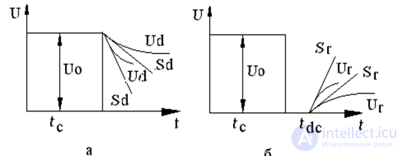
a) decaying voltage Ud;
b) recovery voltage Ur
Figure 5.1 - Change in self-discharge voltage
Method for estimating the service life of cables with polyethylene insulation. This method is based on determining the correlation between the characteristics of the cable insulation and the characteristics directly related to the cable's service life. The main cause of failure of cables with polyethylene (PE) insulation, subjected to prolonged exposure to elevated temperatures and mechanical loads (thermomechanical aging) at operating voltages, is cracking of the cable sheaths and insulation. Crack resistance is quantitatively characterized by the cold-resistance temperature Tx. Various researchers have established that the reduction in service life of cables with PE insulation under operating conditions is caused by structural changes occurring during thermal aging, with the Tx temperature of the PE insulation increasing. Thermal motion of structural elements in polymers and their mobility cause relaxation transitions, which are studied by relaxation spectroscopy methods. Mechanical loss spectra reflect the same molecular motion processes as dielectric losses. As aging progresses, in the a-relaxation region there is an increase in the loss tangent tqdm at the maximum of the temperature and frequency dependence, and, most importantly, the location of the tqdm maximum on the temperature dependences shifts toward higher temperatures ΔΤm by approximately 35 ˚C from the initial state to complete depletion of the service life, and on the frequency characteristics — toward lower frequencies Δfm by approximately 750 Hz. The deviation of the location of tqdm from the initial state, ΔΤm or Δfm, is a quantitative measure for assessing the aging process. This non-destructive method for determining service life can also be applied to other types of insulation.
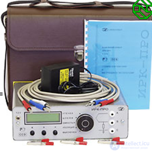
|
Figure 5.2 - "IRK-PRO version 5.10.00" instrument |
The instrument uses microprocessor control, and calculations are performed automatically. The parameters of most commonly used electrical cables are stored in the instrument's memory. Results are displayed on a multi-line alphanumeric display.
Technical characteristics:
- determination of the distance to a defective section with insulation resistance from 0 to 20 MΩ with an accuracy of up to 1 m;
- direct distance readings in meters up to 60 km;
- determination of distance in case of simultaneous damage to all cable cores;
- measurement of loop resistance up to 10 kΩ with an accuracy of up to 0.1 Ω, determination of ohmic asymmetry. The instrument can calculate the cable length of any type from the loop measurement;
- measurement of the cable's electrical capacitance. From the measured capacitance, the instrument calculates the distance to a break in the cable core.
Ranges of measured parameters:
- transition resistance - 0 – 20 MΩ;
- loop resistance - 0 – 10 kΩ;
- insulation resistance - 1 kΩ - 30,000 MΩ;
- electrical capacitance - 1 – 2000 nF;
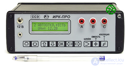
|
Figure 5.3 - "IRK-PRO version 7" instrument |
- test voltage - not less than 350 V.
Cable instrument "IRK-PRO version 7" (Figure 5.3). Has the same technical characteristics as the "IRK-PRO version 5.10.00", but unlike it has the following features:
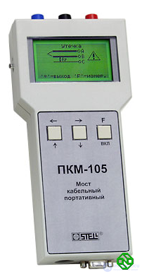
|
Figure 5.4 - PKM-105 portable cable bridge |
- allows automation of the process of measuring, recording, and reading scheduled measurements of insulation resistance and capacitance;
- capable of joint operation with a computer (storage and processing of measurement results);
- self-calibration function provided;
- protection against voltage on the cables being measured is provided;
- the instrument is controlled using micro-buttons. There are no mechanical switches;
- averages measurement results under interference conditions.
Portable cable bridge PKM-105 is designed for measuring cable line parameters and locating faults in telecommunication and power cables using direct and alternating current. The instrument implements bridge methods for measuring loop resistance, ohmic asymmetry, cable capacitance, insulation resistance, and the distance to a break or point of reduced insulation on a cable line (Figure 5.4).
Product features:
- high measurement accuracy;
- simplicity and ease of use;
- clarity of measurements due to on-screen display of measurement schematics (text, graphic, and symbolic information display modes);
- simplified process for measuring the distance to a point of reduced insulation;
- storage of up to 200 measurement results in memory;
- ability to compare cable line parameters with previously measured ones;
- data exchange with a computer via an RS232 serial interface.
Technical characteristics:
- loop resistance measurement range: (0.1…10000) Ω;
- ohmic asymmetry measurement range at a loop resistance of 2 kΩ: (0.1...100) Ω;
- measurement range for distance to leak location at a linear resistance of 50 Ω/km: (0…40) km.
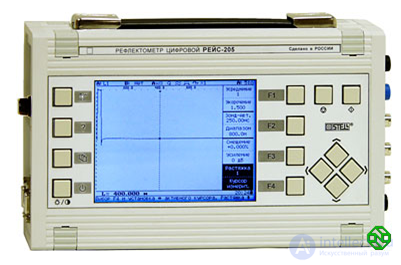
Reis-205 digital reflectometer is designed specifically for identifying various types of cable damage, as well as damage to overhead communication and power lines (Figure 5.5). It implements the bridge method and the pulse reflectometry method.
Functions performed:
- detection and precise determination of the distance to a fault location (short circuit, break, reduced insulation) of lines using the location method (pulse reflectometry method) and the bridge method;
|
Figure 5.5 - Reis-205 digital reflectometer |
- diagnosing the condition of the line by comparing reflectograms, insulation resistance, and other line parameters with previously measured values (with rated data);
- recording measurement results in the instrument's non-volatile memory and on an external computer;
- measuring line length (including on a coil or drum);
- determining the line's characteristic impedance;
- measuring insulation resistance;
- measuring loop (loop-back) resistance;
- measuring ohmic asymmetry (difference in core resistances);
- measuring line capacitance.
The instrument provides clear measurements through the display of reflectograms, measurement modes, measurement schematics, measured parameters, comments, and operator prompts on a large high-resolution LCD screen. Two modes are provided for displaying the reflectogram of the line being measured: single-window mode, in which the instrument screen displays one reflectogram of the line being measured, and dual-window mode, in which the instrument screen displays two reflectograms of the same line. Dual-window mode allows simultaneous observation of both the entire reflectogram and a stretched and amplified section of that reflectogram selected for detailed analysis. The instrument has three inputs for simultaneous connection of three lines and an output to a computer.
"Uspekh AG-5" route-tracing kit is designed for determining the route of cables and pipelines for various purposes, determining their depth of burial, as well as diagnosing fault locations in power cables.
Product features:
- effective extraction of the useful signal under conditions of strong industrial interference through the use of 8th-order filters;
Technical characteristics:
- route determination accuracy: 0.2 m;
- pipeline/cable burial depth: up to 5 m.
TI-01 route tracer is designed for determining the route and depth of burial of energized electrical cables (0.4 - 10) kV at a frequency of 50 Hz, and of pipelines under cathodic protection voltage at a frequency of 100 Hz. The route tracer allows determination of the route of power cable lines located in close proximity to pipelines, and the route of pipelines located in close proximity to power cable lines. The high selectivity of the route tracer is achieved through the use of narrow-band filters.
ISKRA complex is designed to determine the fault location of underground power supply cables of 6 - 10 kV up to 6 km long. The distance to the fault location is determined by the pulse method for all types of faults without preliminary complete burning-through of the insulation, which allows the acoustic fault-location method to be applied immediately after the measurement. The complex is used together with an additional adjustable DC voltage source of 0 - 50 kV, 15 mA, and can be equipped with additional search equipment for detecting the cable route and its fault location.
Complex composition:
- RK-2M combined digital reflectometer;
- GVI high-voltage probing pulse generator;
- DN high-voltage pulse voltage divider;
- charging resistor.
Installation power 5 kW.
|
Figure 5.6– Thermogram of a defective contact connection |
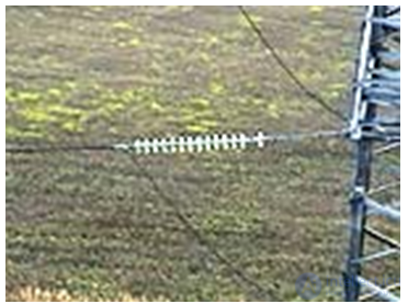
Insulator diagnostics. An important role in ensuring the reliable operation of power supply equipment is played by modern, high-quality diagnostics of network insulation. To date, there are no sufficiently reliable methods for remote detection of defective insulators, nor technical means capable of implementing such methods. Porcelain disc insulators are tested with an industrial-frequency voltage of 50 kV for 1 min before installation, after which their resistance is measured with a 2.5 kV megohmmeter and must be not less than 300 MΩ. Diagnosis of insulators in service is performed using remote monitoring instruments or measuring rods (Figures 5.6 – 5.7). Let us consider what physical effects arise as a result of applying high voltage to an insulator. It is known from theory that if an electric field of sufficient strength is applied to two electrodes separated by an insulator, an electrically conductive layer forms on the surface or within the body of the insulator, in which an electrical discharge — a streamer — arises and develops. The occurrence and
|
Figure 5.7 - Visual inspection of insulators |
the development of the discharge is accompanied by the generation of oscillations over a wide range of frequencies (infrared, i.e. thermal, sound, ultrasonic frequency ranges, in the visible spectrum and over a wide range of radio frequencies). It is therefore obvious that the receiving part of the diagnostic device must detect one or another of the listed consequences of streamer formation and development. Polymer insulators fail in different ways than porcelain or glass insulators, and it is difficult to determine the condition of such insulators in the absence of any observable physical defects such as cracks or blackening.
The ETKL - 10 – 2 complex is designed for:
- testing the insulation of power cables, solid dielectrics, devices and electrical equipment with rectified high voltage;
- burning through defective cable insulation with subsequent burn-through;
- determining the fault location zone of power cables using impulse and oscillating discharge methods;
- determining cable damage using induction and acoustic methods;
- determining the routes and depth of cable line laying;
- determining the presence of couplings and inhomogeneities in cables;
- measuring the insulation resistance of electrical circuits.
An overhead power transmission line (OL) is a device for transmitting and distributing electrical energy over conductors located in the open air and attached to supports or brackets and posts on engineering structures by means of insulators and fittings. Branches to building service entrances belong to OLs.
|
Figure 5.8 - Ultraviolet diagnostics of an OL for the purpose of detecting corona discharges
|
On 110 kV OLs, only suspension insulators are used; on 35 kV OLs and below, both suspension and pin insulators may be used. When an insulator in a string breaks down, its dielectric "skirt" is destroyed and falls to the ground if the skirt is made of glass, while when a porcelain insulator breaks down the skirt remains intact. Therefore, faulty glass insulators are visible to the naked eye, whereas diagnosing failed porcelain insulators is possible only with the help of special instruments, for example, the "Filin" ultraviolet diagnostic instrument.
Overhead power transmission lines (OLs) with a voltage of 35 kV and above are the main lines in power transmission systems. Therefore, defects and faults occurring on them require immediate localization and elimination. Analysis of overhead line failures shows that numerous OL failures occur annually as a result of changes in the properties of the conductor material and their contact connections (CCs): destruction of conductors due to corrosion and vibration effects, abrasion, wear, fatigue phenomena, oxidation, etc. In addition, the number of failures of porcelain, glass and polymer insulators is growing every year. There are many methods and systems for diagnosing the aforementioned elements, however they are, as a rule, labor-intensive, have increased hazard, and, in addition, require disconnecting the equipment from voltage. The method of surveying OLs by helicopter patrol is characterized by high productivity. During a day's work (5 - 6 h) up to 200 km of lines are inspected. During helicopter patrol, the following types of work are carried out:
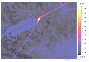
- thermal imaging diagnostics of OLs, insulators, contact connections and fittings for the purpose of identifying elements subject to temperature heating due to emerging defects (Figure 5.6);
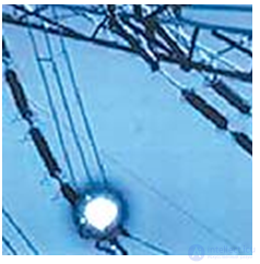
- ultraviolet diagnostics of OLs, insulators, contact connections for the purpose of detecting corona discharges on them (Figure 5.8);
- visual inspection of supports, insulators, contact connections (Figure 5.8, a high-resolution video camera is used).
The use of thermal imagers makes it possible to greatly simplify the process of monitoring the condition of arresters installed on 35, 110 kV overhead lines. Based on the thermogram, it is possible to determine not only the phase of the arrester with increased conduction current, but also the specific defective element that influenced the growth of this current. Timely replacement and repair of defective elements allows further operation of the arresters to continue.
The use of aerial inspections is also increasing in foreign countries as survey technologies develop. For example, the company TVA is working on using high-resolution infrared cameras on a stabilized mount and DayCor cameras for aerial inspections to detect corona on OL elements in daytime, radar for
detecting rotting wooden supports, etc. The formation of corona on OL elements indicates short circuits, cracks or contamination of ceramic insulators, or broken conductor strands. Corona produces weak ultraviolet radiation that cannot be seen in daytime. The DayCor camera, thanks to a filter that passes only ultraviolet radiation in the wavelength range of 240 - 280 nm, makes it possible to detect corona in daytime.
For operational diagnostics of the condition of post insulators and the ceramics of high-voltage bushings, a compact portable vibration diagnostic instrument "Ajax-M" is used. To obtain diagnostic information, an impact is applied to the base of the post insulator, after which resonant vibrations are excited in it. The parameters of these vibrations are related to the technical condition of the insulator. The appearance of defects of any type leads to a decrease in the resonant vibration frequency and an increase in their damping rate. To eliminate the influence of resonant vibrations of structures connected to the insulator, vibration registration is performed after two impacts – on the upper and lower bases of the insulator. Based on comparison of the resonant vibration spectra when striking the upper and lower parts of the insulator, an assessment of the technical condition is made and defects are searched for.
With the "Ajax-M" instrument, it is possible to diagnose the condition of post insulation and search for the following types of defects: presence of cracks in the insulator ceramics or in the places where the ceramics are fitted into the support bases; presence of porosity in the insulator ceramics; determination of the insulator's technical condition coefficient. Based on the diagnostic results, the insulator condition categories are determined – "requires replacement", "requires additional monitoring" or "may be operated". The recorded insulator condition parameters can be saved to the instrument's long-term memory and subsequently to a computer's memory for storage and processing. Using an additional program, it is possible to evaluate changes in the insulator's parameters from measurement to measurement. The instrument can be used to diagnose the condition of insulators of practically any type and brand.
To assess the condition of valve-type arresters, the following tests are used:
resistance measurement;
measurement of conduction current at rectified voltage;
measurement of breakdown voltage;
thermal imaging inspection.
To assess the condition of surge arresters, the following tests are used:
resistance measurement;
conduction current measurement;
thermal imaging inspection.
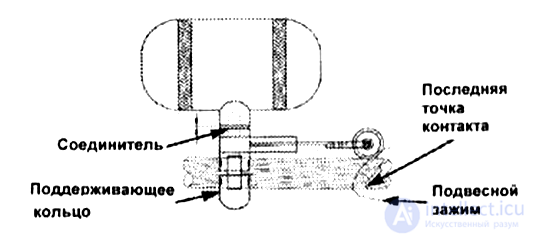
Conductor diagnostics. To determine possible problem areas on power transmission lines arising from vibration, an instrument for monitoring and analyzing conductor vibration on power transmission lines is used. The instrument allows on-site evaluation, under real weather conditions, of the vibration characteristics of power lines with different designs, conductor tension and technical support, and determination of the nominal service life of conductors subjected to vibration. The sensing element in the instrument is a vibration tool used on-site to monitor and analyze the vibration of overhead power line conductors under wind action. It measures the frequencies and amplitudes of all vibration cycles, stores the data in a high-resolution matrix and processes the results to provide an estimate of the average service life of the conductors under study. The measurement and evaluation methods are based on the international IEEE standard and CIGRE procedure. The device can be installed directly on the conductor near any type of clamp.
The instrument consists of a calibrated bracket for a beam sensor, which clips onto the conductor clamp and supports a short cylindrical housing.
|
Figure 5.9 - Instrument for monitoring and analyzing |
Inside the housing are located a microprocessor, an electronic circuit, a power supply, a display and a temperature sensor. The use of bending amplitude (Yb) as the measurement parameter for evaluating the severity of conductor vibration is a well-recognized practice. Measuring the differential displacement at 89 mm from the last point of contact between the conductor and the metal suspension clamp is the standard IEEE reference position for conductor vibration measurements. The sensor - a cantilever beam - senses the bending of the conductor near suspension or hardware clamps. For each vibration cycle, the strain gauges generate an output signal proportional to the bending amplitude of the conductor. Data on vibration frequency and amplitude are stored in an amplitude/frequency matrix according to the number of events. At the end of each monitoring period, the built-in microprocessor calculates the conductor's nominal service life index. This value is saved to memory, after which the microprocessor returns to standby mode awaiting the next start. The microprocessor can be accessed directly from any input/output terminal or computer via an RS-232 communication line.
Flaw detection of conductors and shield wires of overhead power transmission lines. The reliability of OLs depends on the strength of the steel ropes used as current-carrying, load-bearing elements in composite conductors, shield wires, and guy wires. Monitoring of the technical condition of an OL and its elements is based on comparing identified defects with the requirements of standards and tolerances given in the design materials of the surveyed OL, in state standards, the Electrical Installation Rules (PUE), building codes (SNiP), technical specifications (TU) and other regulatory documents. The condition of conductors and wires is usually assessed by visual inspection. However, this method does not allow detecting breaks inside the conductors. For a reliable assessment of the condition of OL conductors and wires, it is necessary to use a non-destructive instrumental method with a flaw detector, which makes it possible to determine both the loss of their cross-section and internal wire breaks.
Thermal method of OL diagnostics. Heat leakage can be detected and an accident related to overheating on overhead lines can be prevented at the earliest stages of its occurrence. Thermal imagers or pyrometers are used for this purpose.
Assessment of the thermal condition of current-carrying parts and insulation of an OL, depending on their operating conditions and design, is carried out:
- by standardized heating temperatures (temperature excesses);
- by excess temperature;
- by the dynamics of temperature change over time;
- with load changes;
- by comparing measured temperature values within a phase, between phases, with known good sections.
The limit values of heating temperature and its excess are given in the regulatory directives RD 153-34.0-20363-99 "Basic provisions of the methodology for infrared diagnostics of electrical equipment and OLs", as well as in the "Instructions for infrared diagnostics of overhead power transmission lines".
For contacts and contact connections, calculations are performed at load currents of (0.6 - 1.0) Irated after appropriate recalculation. The recalculated excess of the measured temperature value to the rated value is performed based on the ratio:
, 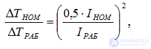 (5.5)
(5.5)
where ΔTrated - temperature rise at Irated;
ΔTop - temperature rise at Iop;
For contacts at load currents of (0.3 - 0.6) Irated, their condition is assessed based on excess temperature. The temperature value recalculated to 0.5 Irated is used as the standard. The following ratio is used for recalculation:
, 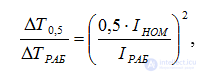 (5.6)
(5.6)
where: ΔT0.5 - excess temperature at a load current of 0.5 Irated.
Thermal imaging inspection of equipment and current-carrying parts at load currents below 0.3 Irated is not effective for detecting defects at an early stage of their development. Defects detected at the specified loads should be classified as defects with an emergency degree of fault. And a small portion of defects should be classified as defects with a developing degree of fault. It should be noted that there is no assessment of the degree of fault severity for defects on indirectly overheated equipment surfaces. Indirect overheating can be caused by hidden defects, such as cracks, inside disconnector insulators, whose temperature is measured from the outside, while the defective parts inside the object are often very hot and severely burned. Equipment with indirect overheating should be classified as having a second or third degree of overheating. Assessment of the condition of connections, welded and crimped, should be performed based on excess temperature.
Inspection of all types of overhead power line conductors using the thermal imaging method is carried out:
- for newly commissioned overhead lines - in the first year of their commissioning at a current load of at least 80%;
- for overhead lines operating at maximum current loads, or supplying critical consumers, or operating under conditions of increased atmospheric pollution, high wind and ice loads - annually;
- for overhead lines that have been in operation for 25 years or more, with rejection of 5% of contact connections - at least once every 3 years;
- for other overhead lines - at least once every 6 years.
Ultrasonic diagnostics of overhead line supports. Assessment of the condition of reinforced concrete supports using an ultrasonic surface sounding instrument. Continuous monitoring of the condition of overhead line supports not only prevents accidents but also significantly increases the cost-effectiveness of operating electrical networks by performing repairs only on those supports that actually need repair or replacement. A significant proportion of overhead line supports in our country and abroad are made of reinforced concrete. A common type of reinforced concrete support is a post in the form of a thick-walled tube manufactured by centrifugal casting. Under the influence of climatic factors, vibration, and operating load, the concrete of the post changes structure, cracks, sustains various damage, and as a result the post gradually loses its load-bearing capacity. Therefore, regular inspections of all posts in electrical networks are required to determine the need for post replacement. Such inspections also prevent excessive rejection of supports.
The possibility of an objective assessment of the load-bearing capacity of centrifugally cast reinforced concrete support posts is based on the fact that as the concrete structure changes and defects appear in it, the concrete strength deteriorates, which manifests itself in a decrease in the propagation speed of ultrasonic vibrations. Moreover, due to the design features of the posts and the nature of the loads on them, changes in the properties of the concrete in the directions along and across the post turn out to be different: the ultrasound speed in the transverse direction decreases faster over time, which can apparently be explained by an increase in the concentration of microcracks with a predominantly longitudinal orientation. Based on changes in the values of ultrasound propagation speeds along and across the post during its operation, as well as their ratio, it is possible to judge the degree of loss of load-bearing capacity of the post and make a decision on its replacement.
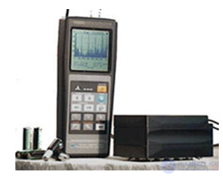
The UK 1401 ultrasonic tester is used as the main measuring instrument for monitoring overhead line supports, designed for measuring the time and speed of propagation of longitudinal ultrasonic waves in solid materials during surface sounding with a fixed base of 150 mm. The ultrasonic tester (figure 5.10) is a small electronic unit with a digital indicator of measurement results and two ultrasonic transducers with dry acoustic contact. Support inspection is carried out with surface sounding of the post material in two mutually perpendicular directions (across and along the post axis) at one or several locations, depending on the type and degree of damage. The surface sounding method allows monitoring at any location on the posts. During inspection, three propagation time measurements are performed
|
Figure 5.10 – Ultrasonic flaw detector for concrete inspection
|
of ultrasound between the tester's transducers in each direction, and the average values of these measurements are determined. Based on the obtained average value of ultrasound propagation time in the transverse direction ("indicator P1") and its ratio to the ultrasound propagation time in the longitudinal direction ("indicator P2"), the actual load-bearing capacity of the support is assessed. Based on accumulated experience in assessing the condition of support posts of various types, limit values of indicators P1 and P2 have been established, upon reaching which the supports must be replaced. Ultrasonic instruments are also used to determine the condition of wooden supports.
Electromagnetic flaw detector for inspecting wires and cables «Intros». The problem of non-destructive testing of overhead line wires and cables is solved by using the two-channel electromagnetic flaw detector «Intros», developed and manufactured by Intron Plus LLC (Moscow). The «Intros» flaw detector is designed for inspecting round-section ropes with a diameter of 6 – 64 mm and flat ropes up to 233 mm wide and up to 38 mm thick. The instrument is used in two modes: real-time monitoring and monitoring with data storage and processing.
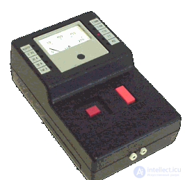
|
Figure 5.11 - "Kvant" instrument for locating single-phase ground faults |
Portable instrument "Kvant" for locating single-phase ground faults in 6 - 35 kV networks. The instrument is designed to determine the location of a single-phase ground fault in 6 - 35 kV networks with isolated and compensated neutral, but can also be used to search for breaks, insulation damage on supports, and remote monitoring of load current and voltage in 0.4 kV networks. In addition, the instrument allows detection of electricity theft in households using a non-contact method (figure 5.11).
The "Kvant" instrument provides:
- monitoring of load current on overhead power lines 0.4 - 35 kV;
- monitoring of voltage presence on overhead lines 6 - 35 kV;
- determination of the location of a single-phase ground fault in 6 - 35 kV networks;
- determination of the location of a wire break in 6 - 35 kV networks;
- determination of which support is energized at 6 - 35 kV;
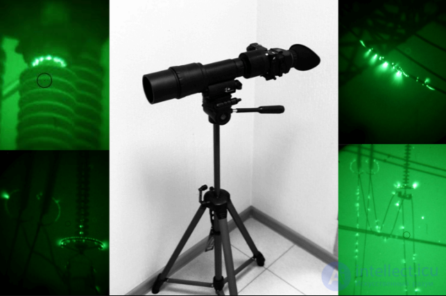
|
Figure 5. 12 - "Filin - 6" ultraviolet flaw detector
|
- light-based check of the serviceability of de-energized fuses or the integrity of an electrical circuit.
Monitoring the presence of 6 - 35 kV voltage is carried out using a built-in electric antenna. The electric antenna is a metal plate located in the front part of the instrument.
Monitoring of overhead line load current is carried out using a magnetic sensor. The magnetic sensor is an inductor coil with an open rod-shaped ferrite core, located in the right part of the instrument. Determination of the location of a ground fault in 6 - 35
продолжение следует...
Часть 1 5. Diagnostics of Cable and Overhead Power Lines
Часть 2 - 5. Diagnostics of Cable and Overhead Power Lines

Comments