
Lecture
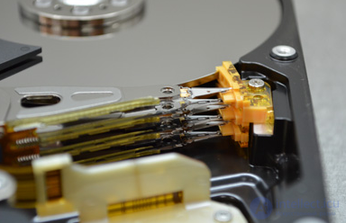
An HDD head is an assembly that, during drive operation, flies above the disk surface using the aerodynamic properties of its slider. To ensure maximum aerodynamic efficiency, the surface of the head's MR element is made perfectly flat and has a specific pattern of recesses and protrusions.
The spindle motor rotation speed of a modern hard disk drive can range from 5400 to 15000 RPM depending on the drive's purpose. Many notebook drives are made low-speed to increase energy efficiency; drives for servers and high-performance platforms are made high-speed. At such rotation speeds, a powerful air flow forms inside the disk, which is used for the aerodynamics of the heads.
However, this air flow also has another effect – the gradual knocking-out of small particles from the ceramic and plastic parts of the head stack assembly that are in direct contact with it. Plain weathering, to put it in terms of school natural science. So that these particles do not damage the surface (although, of course, this cannot be completely avoided) a fine dust trap filter is installed in the disk, located in a place where it can cover the maximum volume of the passing air flow. The fight against microdamage to the surface that does occur is handled through defect management in the hard disk's firmware: defective sectors are entered into the growing defect list and reassigned to good sectors from the disk's reserve.
Failure of hard disk heads is a fairly common problem encountered by data recovery specialists and used in hard disk repair.
The head stack assembly (HSA) of a hard disk drive is a complex electromechanical device designed for reading and writing information on the surface of magnetic disks.
Damage to the head stack assembly is one of the most difficult faults in hard disk drives, in which repair of the drive is impossible even at the manufacturer's factory; data recovery is a labor-intensive process at the edge of what is possible. Data recovery for such faults at home (even with a specialist visit and equipment pickup) is impossible due to the complexity of the technological process, the fairly long execution time (from several hours to several weeks) and the impossibility of creating conditions at home even slightly close to laboratory conditions. Data recovery work on a hard disk with head stack assembly damage is performed only on stationary equipment by highly qualified engineers.
A distinguishing feature of this fault is that the disk, as a rule, makes extraneous sounds (knocking, clicking) and is not detected in BIOS. Sometimes the disk may be detected with an incorrect capacity (but this only happens after the motor stops) – the electronics board switches to service mode; in this case the disk's identification data will show an incorrect capacity: for example 0 bytes or 3.18 GB.
Important to remember:
Opening the hermetically sealed zone of a hard disk should only be done under laboratory conditions – in a clean room, or using a laminar flow cabinet.
A "clean room" is not a room after general cleaning, but a space that falls under the ISO 14644-4-2001 standard.
A "laminar flow cabinet" is not a homemade wooden box with a fan, but an industrial product with a certificate.
There are several causes of head failure, the most common being:
In this article we will examine the last cause. This cause of head stack assembly failure in hard disks (natural wear) is fairly difficult to diagnose. Usually, for the first four causes, everything is more or less clear at practically first glance at the heads, often – even without a microscope. Natural wear, however, is practically invisible to the naked eye.
Why is this needed? Wouldn't it be simpler, upon discovering that the heads are faulty, to simply replace them and read out the data? Alas, no. What we should do to restore access to the data depends on exactly what caused the head stack assembly to fail. Let me explain with an example.
If the heads failed as a result of an impact, then before installing a good assembly into the disk, a detailed examination of the magnetic platters will be required: were they damaged as a result of the impact? Are there any scratches or chips anywhere? Could installing a new head stack assembly without preliminary preparation lead to new damage? As a result – a significantly increased list of preparatory procedures, up to applying special chemicals to the damaged surfaces.
Another example. If the heads failed due to an incorrect emergency parking, a different examination will be required. It will be necessary to assess how the heads are damaged, whether their slider is bent, whether this led to loss of assembly fragments inside the hermetically sealed zone, etc. Accordingly, the order of work during data recovery will, again, be different, up to modification of the parking element inside the hermetically sealed zone and significant modifications to the drive's firmware.
Well, if the heads failed as a result of natural wear, then in the vast majority of cases it will be enough to simply replace the heads and proceed to reading out the information (of course, provided that good compatible spare parts are used). This is precisely why the task of determining the degree of wear of the head stack assembly seems to me quite important.
As a rule, natural wear of the head stack assembly begins to manifest itself long before the hard disk finally fails. Only those who do not monitor the condition of their computer hardware at all fail to notice it. The hard disk has a SMART subsystem, which accumulates error statistics (reallocated sectors, failed start attempts, number of attempts to reallocate a sector, etc.), based on which an approximate forecast of disk failure is made. When the computer starts, the SMART subsystem is polled, and if everything is fine, the computer boots; but if one of the SMART attributes has «dropped» so much that it has gone beyond the normal range, you will see a message on the second POST BIOS screen of this type: Hard Disk Drive XX SMART Status BAD, or something similar in meaning. The computer will only be able to start by pressing one of the function keys (usually F1).
Unfortunately, quite a few users who have problems with the initial computer assembly (for example, incorrect CPU FAN mounting), which leads to the constant appearance of such messages (something like «CPU FAN speed error») and the need to press a function key to continue starting the computer, disable this function in the BIOS. In this case, when the machine starts, all notifications are ignored, and it becomes impossible to see whether there was a notification about a bad SMART status of the disk at startup.
True, the Windows operating system also recognizes disks with a bad SMART status, but for a drive that is actually already dying, this may turn out to be too late. And this mechanism does not always work either, as practice shows: quite often disks with one or two «dropped» attributes may not raise any suspicion in Windows for quite a long time. So — watch the accumulated SMART statistics, it is useful. You can monitor it using a host of free utilities, for example – Victoria.
Disk wear begins from the moment it starts being used, but at first it occurs at a low intensity. After a certain period of time, when the degree of wear reaches a certain critical value, the wear transitions from linear to exponential growth, and the disk transitions into a faulty state fairly quickly.
The main signs of a disk transitioning to the exponential wear stage: rapid growth in the number of reallocated sectors in the SMART report, growth in the number of errors when attempting to reallocate a sector, disk «stuttering», appearance of «ticking» sounds when accessing certain files or folders. At the final stage of wear, a large number of defective sectors appear (the defect management system can no longer cope with the flow of appearing defects), serious slowdowns in disk operation. Failure of a head (or several heads) due to wear – is the apotheosis of this process. The computer stops booting or boots very slowly, you cannot copy any of your files, everything terribly lags, and, finally, it simply stops working. That's it. The heads are worn out and can no longer read anything.
To be fair, it should be said that some drives have an activated firmware lockout system in case of its problems (including – defect management problems). In this case the disk refuses to work (either it is not detected at all, or it is detected but does not report its capacity, or it is detected under its «factory» name, etc.). The lockout prevents critical wear if the disk has come right up to this edge, provided that the user does not try to «start» the disk with repeated power cycling («maybe it'll start»), dances with a tambourine and dubious recommendations from the internet («during a full moon place your disk on the system unit, spit three times into the CPU fan, and when it flies back, say ‘Information come back, hard disk boot up’» and similar unscientific heresy). There is only one correct piece of advice here: take the locked disk to people who understand how to extract data from it.
Microscopy of hard drive heads has long become a standard in the data recovery industry. Examining heads under a microscope makes it possible to identify surfaces with serious damage (dust on the heads, a polished head surface, etc.), and to determine the origin of head damage, etc. However, there is no generally accepted methodology for detecting natural head wear.
Given that head wear is primarily the knocking out of microparticles from its surface as a result of exposure to a strong air current (surface microdamage), it is quite logical that the degree of wear can be assessed by the state of its relief. However, under standard lighting only large defects of the working surface of the MR element can be seen; in order to fully "bring out" the microrelief, two light sources are required: a main one, directed perpendicular to the surface, and a kind of backlight, directed at a small angle (20 – 30 degrees) to the surface. To enhance the "bringing out" of the microrelief, we used ordinary white light from a ring halogen lamp as the main light source, and a cold blue LED was used as the additional ("back") light.
The research setup thus consists of: a MC-VP trinocular microscope; a Canon EF bayonet adapter, a Canon EOS 5D Mark II camera, a Model 2401 ring lamp, and the "back" light source – the microscope's standard illuminator with a replaced LED.
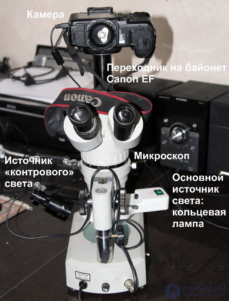
Setup for studying the degree of wear of a hard drive's magnetic head assembly.
Under ordinary direct lighting, only large relief damage is visible on the surface of the MR element. This is understandable: the light comes from top to bottom at a right angle, the light source is on all sides (ring illuminator); in this case, virtually no shadows are cast. Introducing a "back" light source into the lighting scheme allows shadows from numerous surface micro-irregularities to be seen and the nature of the MR element damage to be assessed.
As an example, let's take two identical, fairly old drives, in which the wear process has already been underway for a long time, but one disk is in a critical ("dying") state, while the other is in a state where the SMART status is only just beginning to warn of a possible impending failure of the disk (the disk is only entering exponential wear growth). Seagate ST3160215AS drives, Seagate Barracuda 7200.10 family, 160 GB capacity. The sealed HDA design uses 2 heads. Shooting conditions were identical: ISO 320, exposure 1/30, F 0 (aperture fully open, since shooting is done through the microscope).
The disk in "dying condition" has extremely poor SMART attributes and a huge number of defects. The disk whose SMART has only begun to show an error has an even read graph and less poor SMART attribute values.
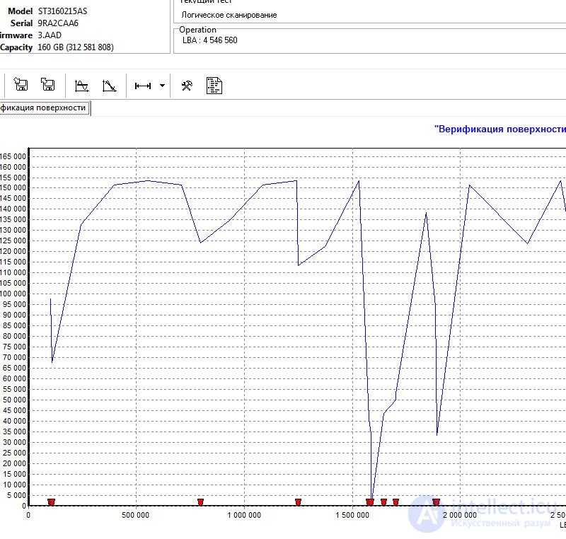
Read graph of the test disk in a critical state of wear, first 3 million sectors
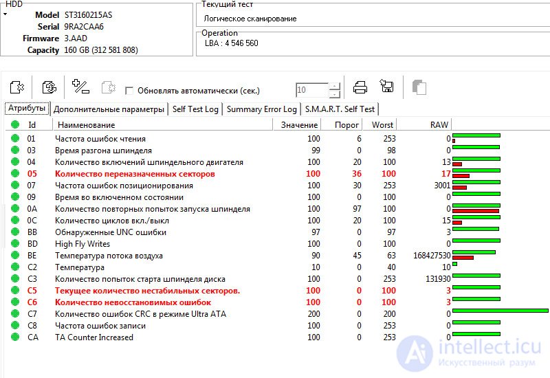
SMART attributes of the test disk in a critical state of wear
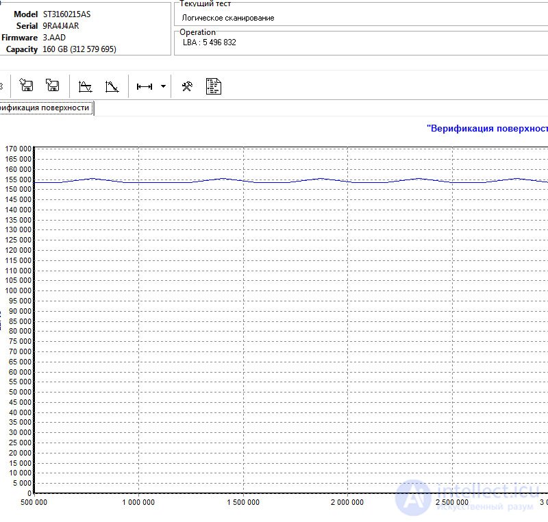
Read graph of the test disk in a precritical state of wear, first 3 million sectors
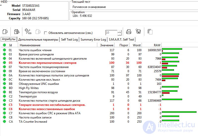
SMART attributes of the test disk in a precritical state of wear
Let's first look at the heads under ordinary top lighting. The surface of the MR element appears even.
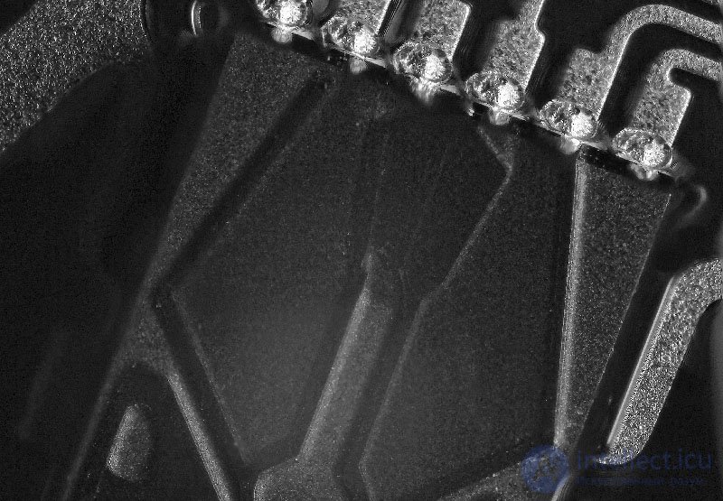
General view of the MR element microrelief of the heads of a Seagate ST3160215AS drive, under direct light source
Now let's turn on the "back" light. The relief picture is transformed: where under ordinary lighting we see depressions, under dual lighting they appear as bumps, and the "graininess" of the surface is noticeably increased.
In the disk with less MR element surface wear, the grain size is relatively finer, but most importantly – there are no large pits. The disk with a greater degree of wear has relatively coarser graininess and has clearly visible large pits on the surface of the MR element.
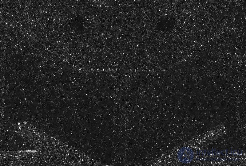
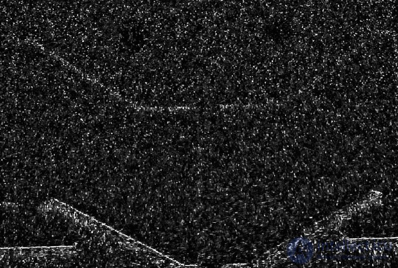
Different degree of microrelief graininess of the same area of the MR element surface of the heads of Seagate ST3160215AS drives with different degrees of wear, scale 100%.
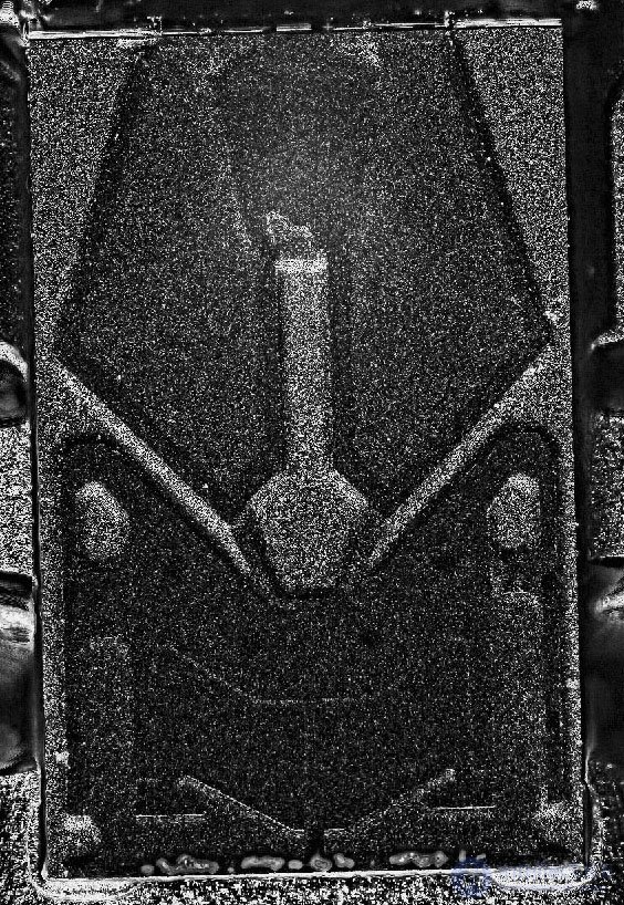
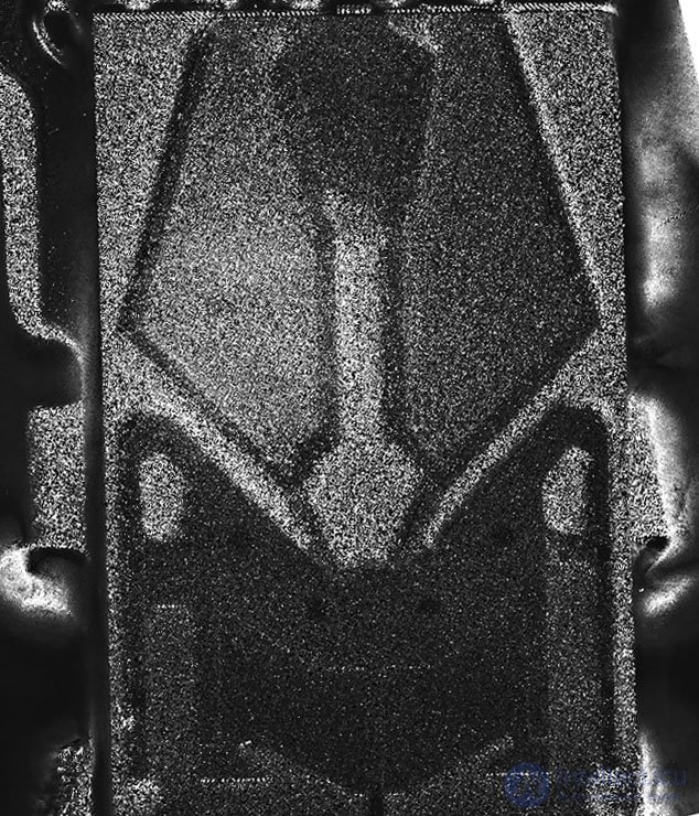
General view of the MR element surface microrelief of the heads of Seagate ST3160215AS drives with different degrees of wear
Using the described methodology makes it possible to determine with a high degree of reliability which hard drive heads have failed as a result of natural wear. I use this methodology for all disks arriving with a diagnosis of "faulty magnetic head assembly," since examining the heads under a microscope is a mandatory part of diagnostics. However, I want to make a caveat: it is extremely undesirable to use point lamps, especially bright LEDs, as the main light source. For ideal revelation of the surface relief, we need uniform illumination of the surface.
thus Diagnosis of a fault when suspecting a problem with the head system is performed in the following sequence
[[b6802]]
[[b9518]]
[[b6790]]

Comments