
Lecture
Technical diagnostics - a field of knowledge covering the theory, methods and means of determining the technical condition of an object. The purpose of technical diagnostics in the general maintenance system is to reduce operating-phase costs by carrying out targeted repairs.
Technical diagnosis - the process of determining the technical condition of an object. It is subdivided into test, functional and express diagnosis.
Object of technical diagnosis - a product or its constituent parts subject to (undergoing) diagnosis (inspection).
Studying and specially preparing radio-electronic circuits substantially simplifies objective planning of tasks for checking operability and troubleshooting faults in radio-electronic devices. objective planning of tasks for checking operability and troubleshooting faults in radio-electronic devices.
The structures of electronic equipment depend on the nature of the tasks they perform, the methods of signal conversion, power supply and control action. For personnel servicing and repairing radio-electronic equipment (REE), all devices included in their
composition are equally important. With any fault in the circuit of electronic equipment, it goes into a faulty state. Therefore, when building models of REE for use in fault finding, all elements must be taken into account.
Structural and functional diagrams of REE are drawn, as a rule, without power supply
circuits, which reduces the amount of information obtained when studying them. The first stage of studying any piece of equipment should include establishing its purpose,
the general operating principles and connections of all elements at the level of the functional units and blocks included in it. Special attention when studying devices, and especially blocks, should be paid to the fact that designers do not always observe the principle of functional proximity.
The circuit representations of a number of electronic devices sometimes differ from the logical
schemes of interaction of their component parts. For example, it is customary to depict the cathode ray tube (CRT) in displays and other devices as shown in Fig. 8.1
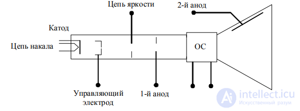
Fig. 8.1. Standard depiction of a picture tube with magnetic beam deflection
If, however, one compares the conditions under which various component parts of the
image appear on the screen, it turns out that the logic of interaction of the CRT circuits and the devices ensuring its operation corresponds to Fig. 8.2. The tube envelope precedes all other
circuits and chains, since regardless of the quality of all other circuits, a fault in the envelope
will result in no image on the screen. The filament circuit follows the envelope, but
precedes all beam control circuits, since with an inactive filament circuit
the electron beam will not appear.
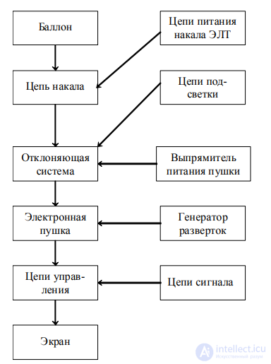
Fig. 8.2. Logic of interaction of CRT component parts
The compilers of operational documentation are primarily concerned with reducing the volume of drawings. Circuits are often placed without regard to the logic of interaction, in whatever free space is available on the drawing field. This causes crossings, returns and overlaps of connections
between circuits, dispersal of their individual circuits to remote parts of the drawing, or transfer to
other sheets. Kinematic and electrical diagrams sometimes contain no indication of the directions of energy transfer or information flows. Information about such directions
can only be found by studying the technical descriptions. Functional diagrams usually do not include power sources, overload protection circuits, built-in diagnostic means and diagnostic information pickup points. Operational and adjustment controls are shown to a small extent in functional diagrams.
When it becomes necessary to find a fault, there is never time for
a detailed analysis of the drawing and description, and the shortcomings of the documentation manifest themselves most
strongly.
If the circuit of the electronic equipment contains more than 100 elements (stages or ICs), then memorizing
the circuit together with the diagnostic means and points becomes difficult. The study of such circuits should be based not on complete memorization, but on the ability
to quickly get one's bearings in them when analyzing the state of the electronic equipment.
In practical diagnostic problem solving, one must be able to recognize the logic of interaction of elements in the circuit of the electronic equipment at any level of division into elements. In doing so, the following must be taken into account:
The second stage requires studying the output characteristics of elements, which are diagnostic parameters. The diagnostic means existing in the electronic equipment, the methods of extracting diagnostic information, and the response of the diagnosed object to operating and test actions are studied.
The third stage of analysis of the electronic equipment is associated with establishing the types of faults that
can occur in each element, and their effect on the values of diagnostic parameters. In doing so, methods of checking and evaluating these parameters are studied and practically mastered.
At the fourth stage, the technology of fault-elimination work and the specifics of assembly-disassembly and installation work are mastered.
The operational documentation of the electronic equipment does not answer all the questions that arise during operation and repair. Studying electrical engineering, radio engineering and mechanics allows, on the basis of general technical knowledge, to fill in gaps in the description and diagrams. This is especially important when selecting, checking and evaluating diagnostic parameters during troubleshooting.
Radio-electronic equipment has a number of typical structures that change little when moving from one component base to another, with changes in circuit operating principles and varying degrees of standardization and unification of designs.
Diagnostics is mainly concerned with studying the interaction of elements of the diagnosed object, regardless of the physical task solved by that object. Therefore, a repair specialist, along with the physics of operation, must know the structure of the diagnosed object (DO), reflecting, above all, the logic of interaction of the elements.
Whereas during initial study of the DO gradual mastery of its various sections and methods of checking is possible, when it becomes necessary to find a fault, immediate recall of the entire DO circuit is required, at least at the level of typical component parts. It is entirely unnecessary to recall the peculiarities of the electrical circuits of all units. One can settle for the elements performing independent functions
(amplification or conversion of signals, transmission of energy).
Power supplies may contain electronic circuit overload protection devices, as well as protective fuse links. Protection devices use thermal and maximum-current relays and electromechanical circuit breakers with sensitive elements that trip on overheating or an increase in magnetic flux or changes in other physical characteristics. Short circuits and severe overloads occur due to insulation breakdown, ingress of moisture and metal objects between electrodes and conductors. Protection means contain sensitive elements which, when the current exceeds the normal value, trip and disconnect the power source from the load circuits. The characteristics of the element are selected so that it trips before damage occurs to the serviceable circuits and the power source.
A device in which high voltages act and which contains elements critical to changes in operating modes always has several stages of protection. This is especially clearly observed in radio transmitting devices, powerful laser installations, some types of control computing equipment, and in radar systems.
In addition, protection means play a special role in electronic equipment, one that receives little attention in descriptions. They serve as indicators of the appearance of severe overloads and short circuits and help locate the place where the short circuit occurred.
Thus, the study of electronic equipment should begin with power sources and their overload protection systems, then trace the circuits supplying energy to various parts of the units and determine the placement of indicators and various kinds of interlocks (from pressure contacts to combination locks).
Special attention must be paid to power branch points, distribution boards and multi-contact connectors. When studying signal conversion circuits, it is necessary to trace the passage of signals from elements located one after another and determine the branch and merge points of sequences. This procedure should be combined with studying the types of signals at the inputs and outputs of elements and the methods of checking them. In addition, the positions of all controls and their effect on the output signals of the elements and of the entire electronic equipment must be noted. It should be borne in mind that the number of different outputs of observation, communication and control means, connected to different parts of the circuits, is small. Among the multi-output electronic equipment can be included a television
receiver with a display. It may contain visual, audio, recording outputs and an electro-optical adapter for transmitting information. All other outputs of such electronic equipment are repeats of the four listed outputs.
When studying electronic equipment for the purpose of troubleshooting, it is important to know:
This information is in a number of cases even more important than knowledge of the physical operating principles of the electronic equipment. Confirmation of this is the successful repair work
of many people who did not receive special education but learned this trade in practice. Analysis of their actions and reasoning during troubleshooting shows that they hold in memory diagrams close to structural ones and partly functional ones, and associate with them the characteristics of the output signals of instruments and the built-in diagnostic means. As experience in troubleshooting accumulates, this knowledge is enriched and allows success to be achieved with incomplete knowledge of the physics of circuit operation. Then gradually comes full knowledge of the device, including the subtleties of the physics of its operation.
Test technical diagnosis - this is diagnosis in which test actions are applied to the object (for example, determining the degree of wear of electric machine insulation from the change in the dielectric loss tangent when voltage is applied to the motor winding from an AC bridge).
Functional technical diagnosis - this is diagnosis in which the parameters of an object are measured and analyzed while it is functioning for its direct purpose or in a special mode, for example, determining the technical condition of rolling bearings from the change in vibration during the operation of electric machines.
Express diagnostics - diagnostics based on a limited set of parameters within a pre-established time period.
Object of technical diagnostics - a product or its components subject to (undergoing) diagnostics (inspection).
Technical condition - the state characterized at a given moment in time, under specific environmental conditions, by the values of diagnostic parameters established in the technical documentation for the object.
Technical diagnostic equipment - hardware and software used to perform diagnostics (inspection).
Built-in technical diagnostic equipment - diagnostic equipment that is an integral part of the object (for example, gas relays in transformers).
External technical diagnostic devices - diagnostic devices structurally separate from the object (for example, a vibration monitoring system on oil pumping units).
Technical diagnostics system - a set of equipment, the object, and personnel required to carry out diagnostics according to rules established in the technical documentation.
Technical diagnosis - the result of diagnostics.
Prediction of technical condition is the determination, with a given probability, of the object's technical condition over an upcoming time interval during which the object's operable (inoperable) state will persist.
Technical diagnostics algorithm - a set of instructions defining the sequence of actions to be performed when carrying out diagnostics.
Diagnostic model - a formal description of the object required to solve diagnostic problems. A diagnostic model can be represented as a set of graphs, tables, or reference standards in the diagnostic space.
[[b894]]

Comments