
Lecture
When we talk about repairing UPS (Uninterruptible Power Supplies), we hold in our hands the key to the reliability and safety of the power supply. In today's world, where dependence on electricity grows every day, knowing how to keep a UPS operational is becoming an essential part of our technical culture.
Uninterruptible power supplies, such as the EATON UPS, play a critical role in ensuring the continuous operation of computer systems, servers, medical devices, and many other important systems. But what should be done when they fail or require regular maintenance? This is the essence of our topic - repairing the EATON UPS and its importance.
Do you use an uninterruptible power supply for your computer?
A UPS is designed to protect the computer, but sometimes it fails itself.
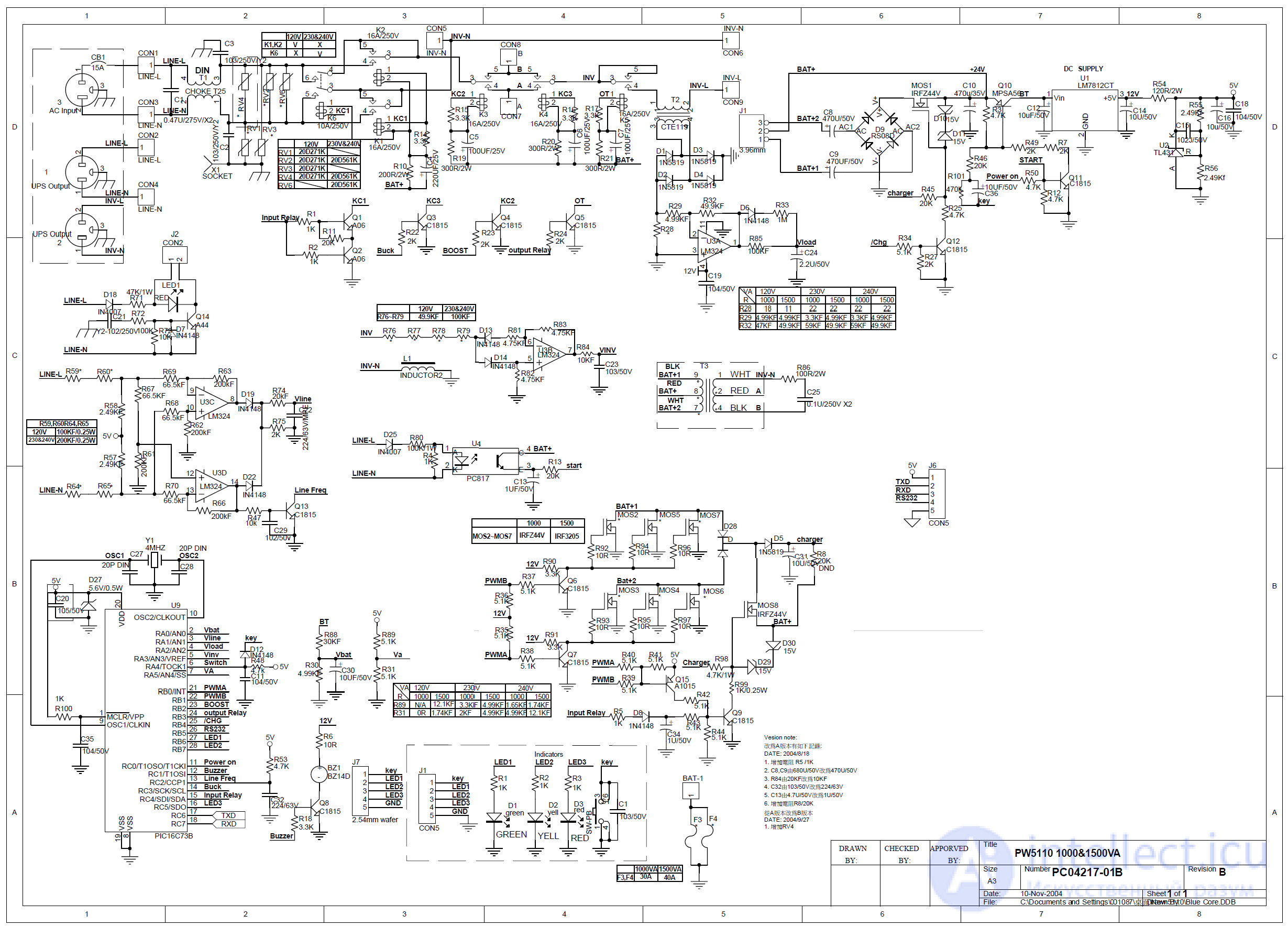
Electrical schematic diagram of the PW5110 1000&1500VA
Key specifications of the PW5110 :
Microprocessor-based system for monitoring and controlling the output voltage
of the load power (AVR)
8 output outlets:
Attention:
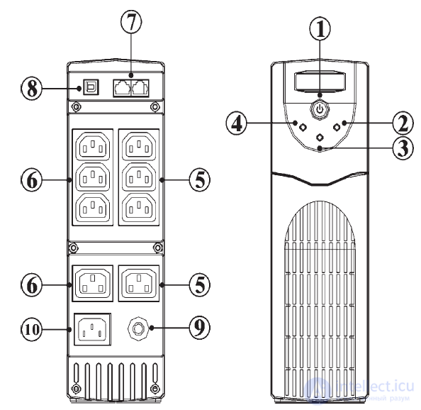
UPS status diagnostics
The UPS provides both visual (indicators) and audible indication of mains status, load status, and potential power supply problems. Visual indication is implemented using 3 LEDs:
Normal operation
Battery operation
Fault or alarm
2. Normal operation indicator (Green)
The indicator stays lit continuously if the UPS is supplying power to your equipment from the mains. When the load power switches to battery operation, the indicator starts to blink.
3. Fault indicator (Red)
The indicator blinks in 2 cases: either the UPS is overloaded, or the batteries need replacement. If the indicator is lit continuously, then either the UPS is faulty or there is a short circuit in the load circuit. A detailed description of the UPS indicator states and their possible causes is given below in the diagnostic table.
4. Battery operation indicator (Yellow)
Lit when the UPS is running on battery power.
Table of LED indicator states for the PW5110

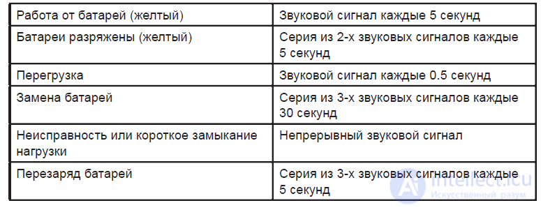
Audible indication of the PW5110
Troubleshooting
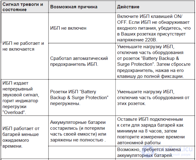
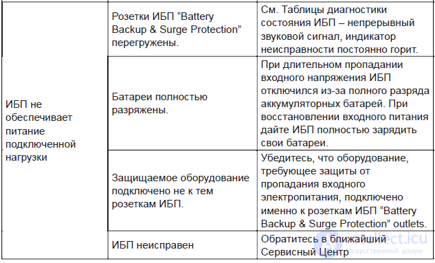
Most likely the battery charging circuit is faulty, or the "standby" voltage monitoring circuit.
There was a breakdown of transistor MOS1, type irfz44.
As a result, charging did not stop when the maximum voltage on the battery was reached, and the processor shut down the UPS.
Why do you think good UPS units are so heavy?
You'll say: because they use lead-acid batteries. Correct! But that's not all. As a rule, they have an autotransformer installed, which allows implementing AVR (Automatic Voltage Regulation) technology.
AVR technology allows switching the autotransformer windings when the mains voltage is elevated or reduced.
This makes it possible to avoid switching to battery power, which saves its lifespan. Recall that lead-acid batteries have a limited number of charge-discharge cycles. Switching the control circuit windings allows the battery to be cycled less frequently.
AVR is a good thing, but the autotransformer (core steel and winding copper) has significant mass, which increases the overall weight of the uninterruptible power supply.
The EATON 800 has no AVR, so there is no bulky transformer in it. This means that the mains voltage from the input goes to the output without change. More precisely, interference is filtered out, but the voltage magnitude does not change.
 With frequent and large changes in mains voltage, the EATON 800 will start switching to battery frequently, and its service life will decrease.
It should be noted that the voltage limits within which the UPS does not switch to battery operation can be fairly wide: from 161 to 284 V. Switching to battery operation will occur only when the mains voltage is lower or higher than these limits, or disappears entirely.
But I don't recommend setting the extended operating limits. At a maximum operating voltage of 284 V, its peak value will be about 401 V. The high-voltage capacitors of the computer's power supply will be charged up to this voltage. Very often, in budget power supplies, two capacitors rated for 200 V (400 volts total) are installed in series after the rectifier bridge.
Most budget power supply units have no varistors or other overvoltage protection. The computer's power supply, at this maximum operating voltage, will be operating at its limit.
Thus, the EATON 800 is designed to operate on "nice and cozy" power grids, where the voltage is relatively stable and doesn't jump around much.
Before putting it on the operating table and giving it anesthesia, let's briefly get acquainted with what this thing is.
The EATON 800 is a passive UPS, designed to protect a PC and rated for an active load of 500 W.
The figure 800 in the name is the apparent power value, which is always greater than the active power. The UPS does not have AVR technology, which helps preserve the battery during frequent voltage surges.
It simply monitors the mains voltage and, as soon as it goes beyond certain limits, supplies power from the battery to the output outlets via a built-in inverter. The rated input voltage limits are 184-264 V. They can be extended to 161-284 V by using the included software. The EATON 800 is managed through a built-in USB port.
The UPS has four output outlets, three of which provide voltage when the mains disappears, while the 4th, Eco control, only provides protection from interference.
It should be noted that these UPS units have low reliability. It's hard to say what this is caused by more — circuit design flaws or unreliable components.
EATON 800 faults are accompanied by characteristic symptoms:
after the mains voltage disappears or surges, the UPS emits a constant beeping,
a red indicator on the front panel may light up.
When the UPS beeps continuously, the first thing to do is disconnect the battery.
If this is not done, the faulty circuit will continuously draw current from the battery and discharge it down to 8 volts or lower, until it stops. This will be a mode of very deep discharge. To restore such a battery afterward, you'll have to try really hard!
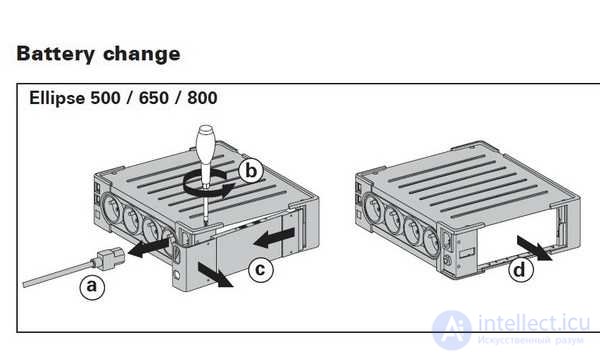 To replace the battery, unscrew one screw, whose head is designed for a Phillips (cross-shaped) screwdriver. Then lift the corner of the side cover, release the two latches, remove this part, and disconnect the battery terminals.
The remaining three screws have heads designed for a T10 star (Torx) bit, but they can be unscrewed with an ordinary flat screwdriver with a narrow blade.
 The board is attached to the housing with two T10 star screws. You can disconnect terminals P1, P4 – P8, which supply voltage to the output outlets, to make it easier to access the PCB assembly.
Connected to the main board are:
the indication board with the power button,
the board with the control controller (the ST72F324 chip in a 32-pin TQFP package),
the interface board with RJ-45 and USB connectors.
Faults should be looked for on the largest board.
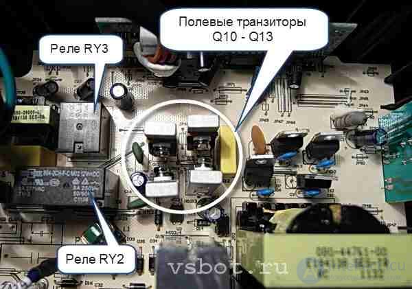
 First of all, you should check field-effect transistors Q10 — Q 13.
They are installed in a compact group, each on a small aluminum heatsink.
To test the transistors, you can use a digital multimeter in diode "continuity" test mode.
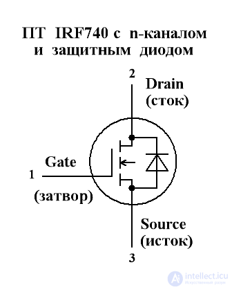
The n-channel IRF740 transistors used here have an on-channel resistance Rds of about 0.5 ohm, a drain current of 10 A, and a maximum drain-source voltage of 400 W.
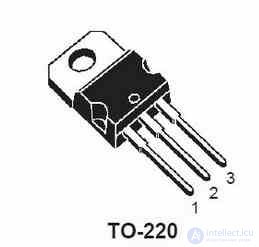 The drain-source channel is protected by a built-in diode connected in reverse.
Thus, the drain-source channel should test like an ordinary diode: when the red probe (positive) of the meter is connected to the source and the black one (negative) to the drain, the built-in diode will be forward-biased, and the meter display will show a value of 0.5 — 0.6 volts.
This is the voltage drop across the forward-biased diode. If you reverse the probe polarity, the built-in diode will be reverse-biased, and the display will show a one in the leading digit.
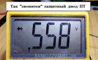 If the channel is shorted, the display will show not a one, but some voltage drop value.
To confirm the channel is shorted, switch the tester to resistance measurement mode on the 200 Ohm range and repeat the test.
With a shorted channel, the test will show some resistance value at both probe polarities.
It should be noted that if the channel tests like a good diode, this does not yet guarantee the transistor is fully functional.
Therefore, it is necessary to check the gate-source and gate-drain sections with the tester in resistance measurement mode. The IRF740 has an insulated gate, so there should be no resistance at all on the 200 Ohm range.
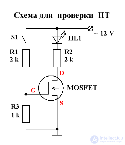 Those who like to dig deeper can build a small circuit for an unambiguous assessment of the transistor's serviceability.
When button S1 is pressed, the LED should light up, and when released, it should go out.
It is convenient to use an IC socket, into which the transistor is inserted, on which the rest of the test circuit's components are mounted.
A faulty transistor should be replaced with an identical one.
It should be noted that the EATON 800 is rated for an upper mains voltage limit of 284 V (peak value 401 V). The IRF740 has a maximum drain-source operating voltage of 400 volts. Not much margin!
Instead of the IRF740, you can install an IRF840 transistor with a drain-source operating voltage of 500 volts, drain current of 8 A, and drain-source channel resistance of 0.85 Ohm. This transistor has somewhat worse figures for resistance and drain current, but a higher operating voltage. The pinout and package of these transistors are the same, so the replacement will go without problems.
Another weak point of the EATON 800 is the electromagnetic relays installed on the main board. Two types of relays are used:
833H-1C-C with one group of switching contacts (RY3, RY1)
894-2CH-F-C with two groups of switching contacts (RY2).
Both relays have a 12 V DC coil. During operation, the relay contacts get burnt and their contact resistance increases. This leads to disruption of normal operation.
Relays with burnt contacts are best replaced.
If this is not possible, you should apply a constant 12 V voltage to the coil from a battery or another source several times. When the relay activates, its contacts come into contact, get cleaned, and their contact resistance decreases.
According to the datasheet (reference data), the resistance of the closed relay contacts should not exceed 0.1 Ohm.
Voltage can be applied to the coils without desoldering the relay from the board. But this should be done carefully and attentively, without mixing up the polarity of the applied voltage. The fact is that diodes are connected in parallel with the relay coil to protect the rest of the circuit from the self-induction EMF that occurs during switching.
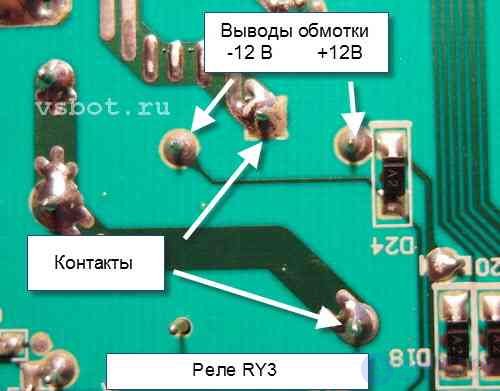 When voltage is applied to the winding, the diode connected to it should be closed (non-conducting). If you mix up the polarity, you can burn out the diode.
That is, the "plus" should be applied to the cathode (the line marking), and the "minus" of the applied voltage to the anode. Diodes have a line marking near the cathode on the case.
Diode D24 is connected in parallel with the RY3 relay winding, and diode D29 with the RY1 relay winding.
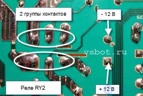 It is a good idea to measure the resistance of the closed contacts with a multimeter before applying 12 V to the coils and after. Basically, click the relays a few times, then place the probes on the contacts, apply voltage to the windings, and measure the resistance of the closed contacts.
The winding resistance of the 833H-1C-C relay is 400 Ohm plus or minus 10%, and of the 894-2CH-F-C relay 180 Ohm plus or minus 10%.
That's all, friends. Check the transistors and relays, replace them if necessary, and work in good health!
In conclusion, let us note that extended voltage limits can be set not only via software, but also using the buttons and indicators on the front panel. But I do not recommend setting the upper level to 284 V. It's risky…
Before closing the side cover, check whether the battery is charging.
It should be charging even if the UPS is not switched on (but the mains cable plug is connected to the supply mains). If the charge current is too small (a few milliamps), the battery needs to be replaced.
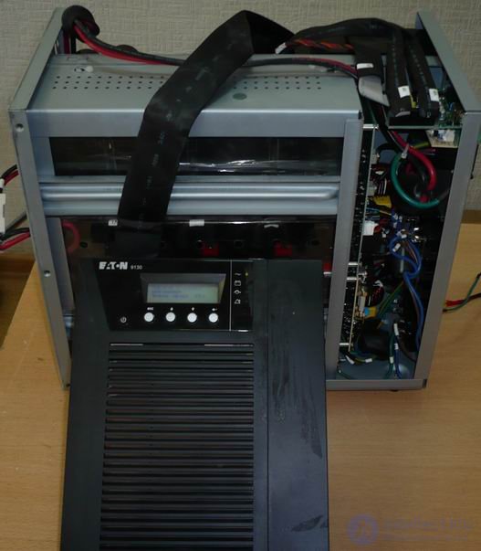
Fig. 1 EATON PW9130i3000T-XL UPS
An EATON PW9130i3000T-XL UPS came in for repair; when switched on, the error indicator on the front panel lit up, the UPS emitted a periodic beep, and the display showed a persistent "UPS starting up" message. Swapping phases at the outlet did not help. The log produced a bunch of messages, the essence of which was that the inverter does not start (at event #298 ABM discharge - testing was stopped). This means the UPS has broken down and requires repair. As expected, no schematics were found online, though perhaps the search just wasn't thorough enough.
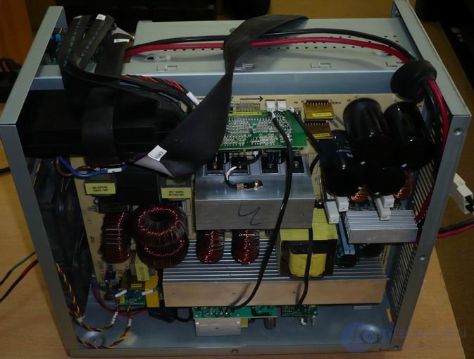
Fig. 2 EATON 9130 UPS, power board.
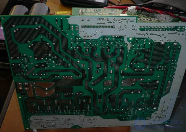
Fig. 3 EATON 9130 UPS, power board.
The fault was identified by visual inspection, but the price tag on the power switches made the technician sad — simply replacing them and seeing whether it blows up or not turns out to be expensive. Had to draw up the schematic of the driver for the power switches.
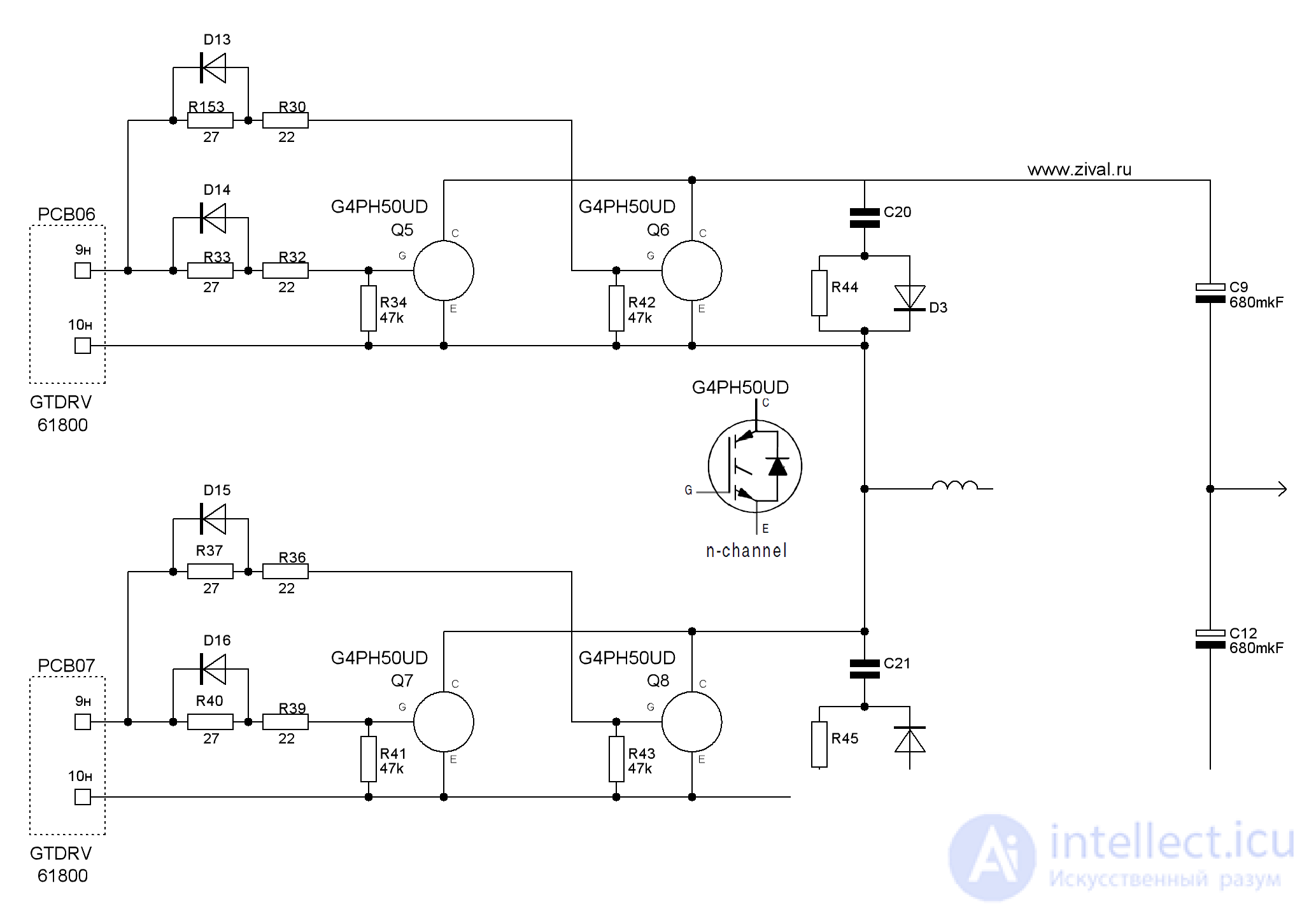
Fig.4 EATON 9130 UPS, schematic No. 1, power switches
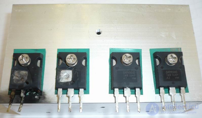
Fig. 5 As can be seen from the photo, there were no problems with diagnostics.
There are 4 power switches, n-channel IGBTs G4PH50UD (1200V, 24A). Two switches are connected in parallel with each other to increase the current handled, and both pairs are connected in a classic half-period pair configuration, which allows reducing the voltage applied to the transistor by 40%.
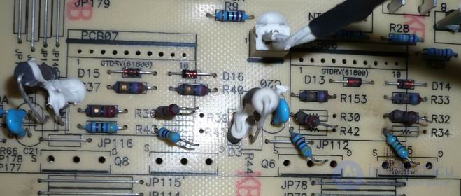
Fig. 6. Power section - R32,R30 (22 Ohm) are faulty. Power switches and drivers have been removed.
As can be seen from the schematic, the gate resistors R30, R32, R36, R39 (22 Ohm) are the first candidates for replacement, which is confirmed by continuity testing on the board, although R36, R39 (22 Ohm) survived. A good sign is the integrity of the gate resistors R33, R37, R40, R153 (27 Ohm) — most likely they were protected by a diode connected in parallel, which means the probability that the drivers survived is very high.
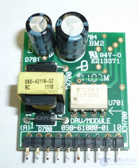
Fig. 7 Power switch driver 61800, top view
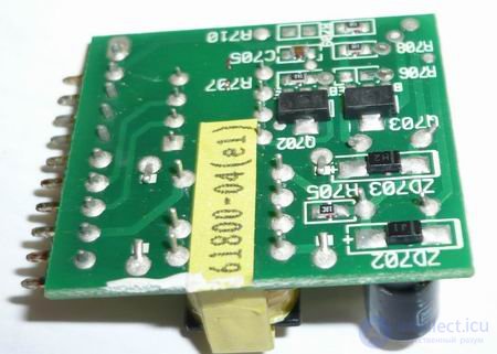
Fig. 8 Power switch driver 61800, bottom view
For peace of mind we remove and check the power switch drivers. The general operating principle of the driver is clear, but how it all works together is not entirely clear, and to be honest there's no desire to dig into it.
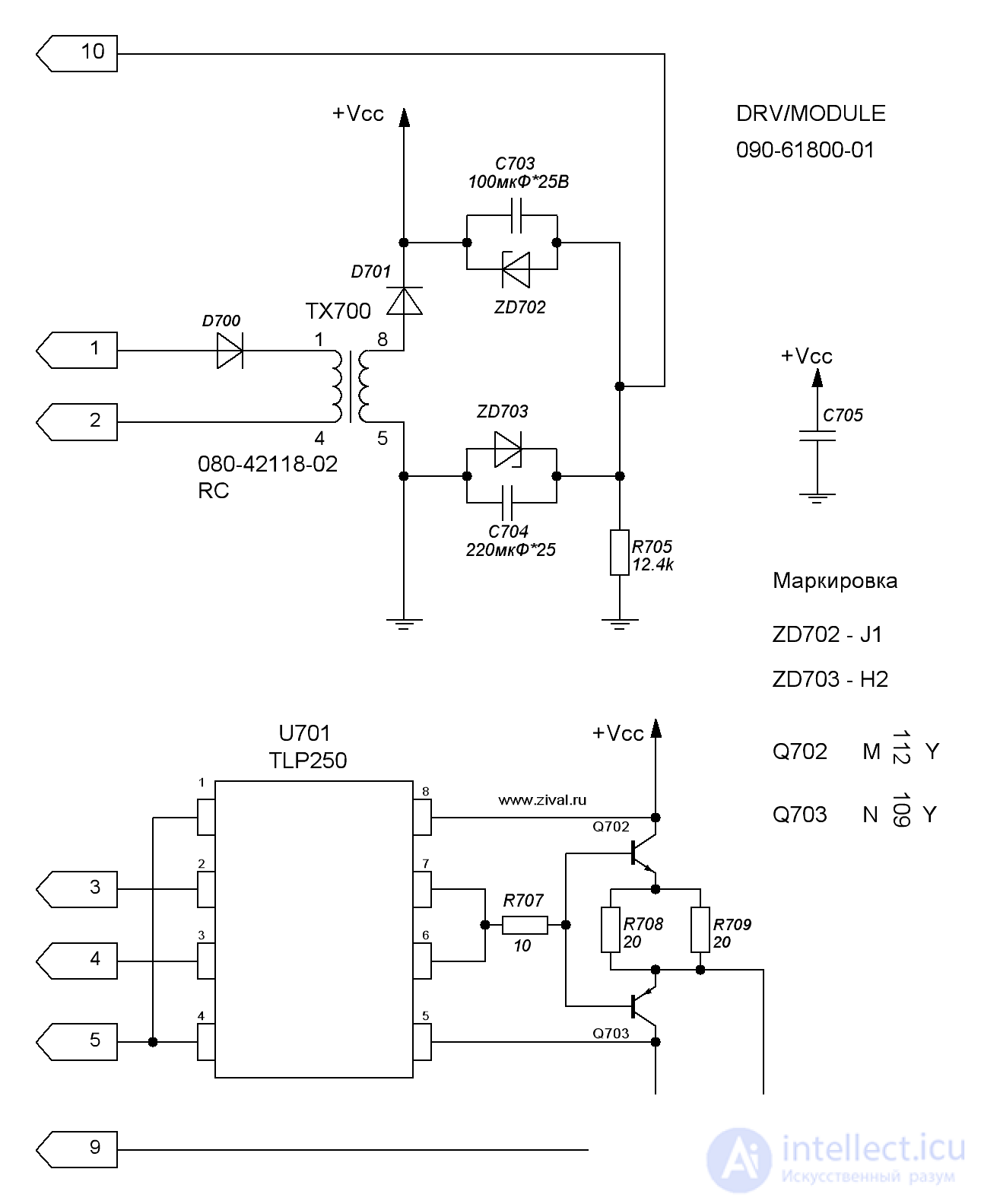
Fig. 9 EATON 9130 UPS, schematic No. 2, power switch driver.
The driver consists of a specialized driver for IGBT transistors U701 (TLP250), whose output feeds a signal inverter made of two transistors Q702, Q703.
Since the drivers are alive and the faulty resistors have been replaced, it can be switched on. It should be noted that the insulating pads were also replaced, as they did not survive the transistor removal. We replace all four!!! power switches, preferably from the same batch — any mismatch and it's all wasted again, although the circuit does allow replacing just the two paired switches, but we decided not to experiment.
But it turns out that the battery pack, made of 8 batteries connected in series, by the way 96V at the output is life-threatening, is faulty. Two batteries treacherously sag. So we replace the batteries too. You can imagine how much the repair ends up costing!
We switch on — charge, and watch. Charging up to 90% goes in bulk (constant-current) mode, after 90% in trickle mode. So it's better to charge the batteries separately, but we didn't have a 115V charger, so we charged them as part of the UPS — the repair ended up dragging on for 72 hours. Unpleasant hours — the UPS is as noisy as a good tractor, and easily out-noises a microwave; let's just say the UPS is only suitable for a server room, but not at all for home use.
On the road to knowledge and skills, my friend, you have taken an important first step, mastering the art of EATON UPS repair. This is only the beginning of your exciting journey in the world of the technical workshop. Many more interesting challenges and tasks lie ahead, but undoubtedly, it will be an exciting adventure full of discoveries.
Your ability to learn and your drive for growth are your secret to success. Feel free to give feedback and comments, share your findings and experience with the community. In this exchange of knowledge and experience you will find not only satisfaction, but also valuable friends, ready to support and inspire you.
And remember, that knowledge of EATON UPS repair is not just a skill, it is an opportunity to make the world more reliable and more resilient. You stand guard over uninterruptible power supply, and this is important. After all, in your hands lies part of the responsibility for the safety of technological processes and important data.
So keep moving forward, keep searching for new things, and together with your knowledge of EATON UPS REPAIR, you will surely achieve your goals. You are ready to create reliability in this world, and that is a great thing. Onward, to new heights!

Comments