
Lecture
Ultrasonography (ultrasound) is a method of examining the structure of any internal organs using reflected ultrasonic waves. It is an absolutely safe and painless diagnostic procedure.
Ultrasound can be performed an unlimited number of times, including for pregnant women, without risk to health. Ultrasound examination is a more superficial method compared to magnetic resonance imaging (MRI), but is often sufficient for diagnosing various injuries. Ultrasound can detect and visualize lesions and tissue changes that are tiny and imperceptible to other examination methods. Ultrasonography is a health-sparing way of examining the soft tissues of the body, in which high-frequency waves - ultrasound - are used to obtain an image.
No medical referral is required to have an ultrasound scan. After the procedure you receive the images and the radiologist's report.
In the tissues of the body, as in any solid, liquid or gaseous substance, mechanical (elastic) oscillations and waves can arise. Mechanical oscillations and waves at a frequency below 16 Hz are called infrasonic. The therapeutic application of such oscillations can be seen in the example of vibration massage. Mechanical oscillations and waves in the frequency range from 16 Hz to 20 kHz are called sound waves and are perceived by the ear. Mechanical oscillations and waves with a frequency above 20 kHz are called ultrasonic (or simply ultrasound) and are not perceived by the ear. The upper limit of the ultrasonic oscillation spectrum has not been established. At present, ultrasonic oscillations with a frequency of several hundred million hertz are obtained.
In therapeutic practice, continuous ultrasonic mechanical oscillations with frequencies of 22—44 kHz, 880 kHz and 2640 kHz are used. For pulsed therapy, series of low-frequency pulses with fill frequencies of 1 and 3 MHz, duration 0.5—10 ms and pulse repetition rate 16–100 pulses/s are applied. Pulsed modes are used to achieve non-thermal effects. The ratio of the non-thermal and thermal components of the therapeutic action of ultrasonic oscillations is determined by the intensity or mode (continuous or pulsed) of exposure. The intensity of the generated ultrasonic oscillations in continuous mode is 0.05-2 W/cm2, in pulsed mode – 0.1 - 2 W/cm2. The effective exposure area ranges from 0.7 to 5.4 cm2. Over the past twenty years, several types of ultrasound therapeutic apparatus have become widespread in therapeutic practice: stationary - UTS-1 and UTS-1M (frequency 880 kHz); portable UTP 1, UZ-T5, UZT101, UZT-104, LOR-1A, LOR-3 with a frequency of 880 kHz and UTP-3M (2640-2950 kHz), UZT-31 (2640 kHz). At present, UZT apparatus are used to perform the therapeutic action
In sound and ultrasonic waves, particle oscillations occur in the same direction as wave propagation. Such waves, called longitudinal, consist of alternating regions of compression and rarefaction of the substance, moving in the direction of wave propagation. In solid substances, in addition to longitudinal waves, transverse sound or ultrasonic waves can also form.
The distance between two nearest points of a wave oscillating in the same phase (for example, between the centers of two neighboring compression or rarefaction regions) is called the wavelength. Between the frequency of ultrasonic oscillations f and the wavelength λ there is a relationship
λ =c/f, where c —is the speed of wave propagation in the given medium. The speed of propagation depends on the elastic properties and density of the medium; it is higher in liquids than in gases, and higher in solids than in liquids.
In air, ultrasonic waves propagate at a speed of about 330 m/s. The speed of ultrasound propagation in various soft tissues of the body is in the range of 1445—1600 m/s, differing by no more than 10% from the speed of propagation in water (about 1500 m/s).
In bone tissue the speed of propagation is higher — about 3370 m/s. Thus, at the frequency of 880 kHz most commonly used in ultrasound therapy, the wavelength in water and soft body tissues is on the order of 1.6—1.8mm.
To create and sustain an ultrasonic wave, a constant transfer of the oscillation source's energy into the medium is required. This energy, in the process of oscillation of the medium's particles around the equilibrium position, is transferred from one particle to another so that in the ultrasonic wave, energy transfer occurs without transfer of the substance itself.
The amount of energy transferred in 1 s through an area of 1 cm2, perpendicular to the direction of wave propagation, is called the intensity of ultrasonic oscillations. Since the amount of energy per 1 s is power, the intensity is equal to the oscillation power per 1 cm2.
The oscillatory movements of substance particles occurring in an ultrasonic wave are characterized by a very small displacement amplitude and extremely large accelerations. Thus, for example, at a frequency of 880 kHz, particles of body tissues in which a wave with an intensity of 2 W/cm2 propagates (the maximum intensity used in ultrasound therapy) oscillate with an amplitude of about 3.5-10"6 cm. The maximum acceleration in this case reaches 90-106 cm/s2, which exceeds the value of free-fall acceleration of bodies by almost 100 thousand times.
The oscillating particles of the substance are acted upon by significant magnitudes of variable (acoustic) pressure. Thus, for example, in the therapeutic application of ultrasound with the above parameters, the amplitude of the variable pressure reaches 2.7 atm.
The enormous accelerations and significant pressures experienced by the particles of the medium during ultrasonic oscillations largely determine the effect of ultrasound (including its therapeutic effect) on body tissues.
As an ultrasonic wave propagates, losses of energy occur due to heating of the medium's particles. The intensity of the ultrasound decreases in this process according to an exponential law. The concept of "penetration depth" is used to characterize this process. Penetration depth is equal to the distance to the surface at which the intensity of the ultrasonic wave has decreased by a factor of e (e = 2.7 — the base of natural logarithms). The absorption of energy increases with the oscillation frequency, and the penetration depth decreases accordingly. At a frequency of 880 kHz, the penetration depth of ultrasonic energy into muscle tissue is about 5 cm, into fatty tissue — about 10 cm, into bone — about 0.3 cm. The low energy losses in layers of fatty tissue, and consequently their insignificant heating, combined with sufficient penetration of energy into the muscles, provide good conditions for the therapeutic application of ultrasound.
At the same time, the distribution of ultrasonic energy among the layers of body tissue has a characteristic feature, namely the intensive heating of bone tissue. This distinguishes the action of ultrasound from the action of an electromagnetic wave and must be taken into account when carrying out ultrasound therapy procedures.
The source of ultrasonic waves is some body that is in oscillatory motion at the corresponding frequency. To obtain ultrasound with a frequency of several tens of kilohertz, the phenomenon of magnetostriction is usually used, which consists in the fact that, under the action of a variable magnetic field, the le: ngth of a rod made of ferromagnetic material positioned along the field changes somewhat. This periodic lengthening and shortening of the rod sets into oscillatory motion the particles of the medium adjacent to the ends of the rod, in which an ultrasonic wave is formed. In medicine, for therapeutic purposes, ultrasound of a relatively high frequency of about €00—3000 kHz is used, which is obtained by means of the so-called inverse piezoelectric effect. The inverse piezoelectric effect consists in the fact that in many crystals (quartz, Rochelle salt, barium titanate, etc.) under the action of an electric field, a certain mutual displacement of the polar groups of atoms making up the basic structure of the substance occurs, which causes a corresponding change in the dimensions of the crystals.
Between air and the body, almost complete reflection of the ultrasonic wave occurs. Therefore, there must be no air gaps between the applicator head and the patient's body. For this purpose, the surface of the irradiated area of the body is covered with a layer of an intermediate medium, usually vaseline oil, which fills all possible air gaps between the emitter and the body.
On body surfaces of complex shape, for example the foot, exposure to ultrasound is carried out through water in a basin (fig. IV—4). The limb and the emitter are placed in a basin of warm water. The emitter is either positioned motionless at a small distance from the body surface, or is slowly and smoothly moved over the area of exposure. If exposure from below is required, a flat metal reflector is installed at the bottom of the basin, directing the emitter's wave onto the irradiated surface.
The action of ultrasonic oscillations on body tissues has a complex mechanism, in which three main components can be distinguished: mechanical, thermal and chemical.
The mechanical action of ultrasound, caused by oscillations of tissue particles, represents a peculiar "micromassage" of the tissues. The changes in the mutual spatial arrangement of cellular structures occurring in this process lead to their restructuring, to shifts in their functional state. The chemical action of ultrasound is a consequence of the aforementioned mechanical and thermal effects. The main biochemical shifts caused by ultrasound are changes in the intensity of oxidative processes, enhancement of diffusion processes, and others.
Dosimetry in ultrasound therapy consists in setting the specified value of ultrasound intensity and the duration of exposure. Intensity in W/cm2 is usually indicated on the scale of the apparatus's output power regulator; the usual intensity values applied with the mobile technique are 0.5—1.5 W/cm2, with the stationary technique 0.05—0.3 W/cm2.
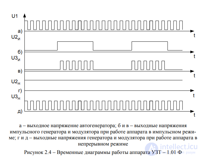
In addition to continuous action, a pulsed (intermittent) exposure mode is also widely used in ultrasound therapy. In this case the pulse duration is adjusted within the range of 4-10 ms, at a repetition frequency of 50 Hz. The average intensity of oscillations in this case is less than that indicated on the scale by as many times as the pulse duration is shorter than the repetition period.
During operation, periodic monitoring of the calibration of the intensity regulator scale must be carried out. For this purpose, the output ultrasonic power of the apparatus is measured using a special instrument. From the known values of power and the working area of the emitter, the intensity of the ultrasonic oscillations can be determined. Power measurements are based on the fact that a propagating ultrasonic wave exerts constant pressure on the surface of a body that obstructs its propagation. The magnitude of this pressure, with total reflection from the obstacle, is directly proportional to the intensity and inversely proportional to the speed of ultrasound propagation. Although the pressure exerted by the wave is very small (at maximum therapeutic intensities in water or body tissues — ten-thousandths of an atmosphere), it can be measured with sensitive instruments (see § 2 of section 2), which are calibrated in terms of the power radiated by the ultrasound source.
At the same time, in distributing ultrasonic energy between layers when using emitters with an area of 0.5 and 1 cm2, to avoid their overheating the 1.5»and 2 W/cm2 steps should not be used in continuous mode. | | * When the set procedure time has elapsed, an audible signal sounds, and the red lamp behind the procedure-timer dial goes out. At the end of operation, the apparatus is switched off by pressing the «Off» button.
The UZT-31 apparatus for ultrasound therapy. The apparatus is intended for the treatment of obstetric-gynecological conditions, but is also used in otorhinolaryngology, dentistry, dermatology and other fields of medicine.
Main technical data of the apparatus:
Block diagram of the UZT-31 apparatus
The high-frequency generator produces unmodulated electrical oscillations with a frequency of 2.64 MHz. Power amplification of these oscillations takes place in the output amplifier, to which one of the ultrasonic emitters is connected, converting electrical oscillations into mechanical ones. The modulator is designed to produce a pulsed mode at three pulse durations — 2, 4 and 10 ms, and a constant repetition frequency — 50 Hz. The power supply unit provides constant-voltage power to the circuits of the modulator and generator.
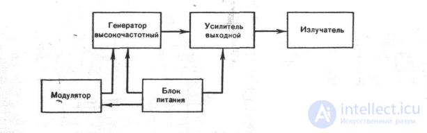
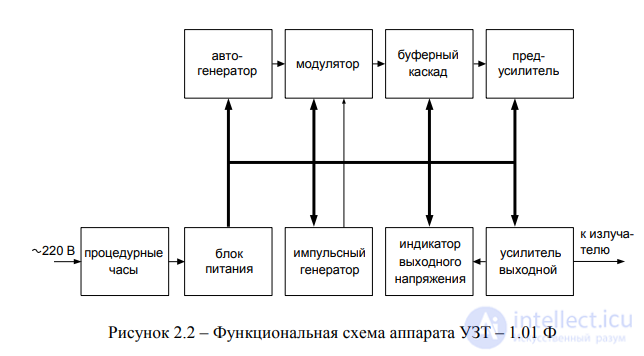
The schematic electrical diagram of the apparatus is shown in fig. IV—9, the diagram of the units in fig. IV—10—IV—12.
The high-frequency generator unit (fig. IV—10) includes a self-oscillator, a buffer stage and an amplifier. . The self-oscillator (transistor V2) is built according to an oscillator circuit with crystal stabilization. From the output of the self-oscillator, the high-frequency voltage is fed to the buffer stage, which is an emitter follower (transistor V4). The emitter circuit of the follower includes the contacts of pushbutton switch S1, which switch the divider on resistor 9 and potentiometers 10—13. The switch buttons are brought out to the apparatus's control panel («Intensity, W/cm2»). When one of the buttons is pressed, the corresponding potentiometer is switched into the emitter circuit, from whose wiper the voltage is fed through coupling capacitor 11 to the amplifier. By means of potentiometers 10—13 the intensity is adjusted at each step during production of the apparatus or its repair.
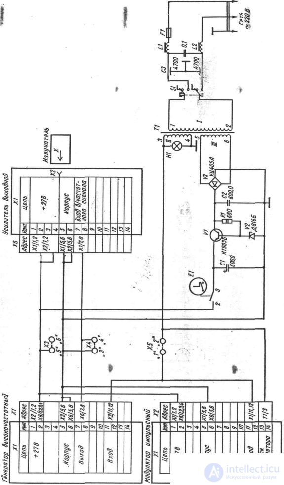
Schematic electrical diagram of the UZT-31 apparatus.
The amplifier (transistor V5) has at its output a four-terminal network (capacitors 13—17 and inductor 3), matching the output resistance of transistor V5 with the input resistance of the output amplifier (see below). The generator unit also contains the output stage (transistor V3) of the pulse modulator. The stage operates in switching mode according to a parallel circuit. When a rectangular pulse is applied to its input (through contacts 11—12 of plug XI) transistor V3 turns on, shunting the input of the buffer amplifier and thereby creating a pause in the generation of ultrasonic oscillations.
The pulse modulator (fig. IV—11) is built on digital microcircuit D1 and analog A1. The mains-frequency voltage taken from winding 3—4 (see fig. IV—9) of the power transformer is fed, through contacts 13—14 of plug XI to the input of a Schmitt trigger built on two elements Dl,l and D1.2 of digital microcircuit D1, Zener diode VI and resistor 1 — input protection elements of the microcircuit. The rectangular pulses coming from the output of the trigger, following at the mains frequency, trigger a monostable multivibrator (microcircuit A1, capacitors 1—5, potentiometers 3—5). The duration of the pulses generated by the monostable multivibrator is set by means of pushbutton switch S1 (the «Operating mode» buttons on the control panel). When one of the chains is connected to terminals 3—4 of the microcircuit — R3 — C2, R4 — C3, R5 — C4, C5 — the pulse duration will be 2, 4 or 10 ms respectively. Setting the nominal value of the pulse duration is done by means of potentiometers 3—5.
From the output of microcircuit A1 (pin 5) the pulses pass through an inverter (element D1.4) to the input of the modulator switch (contacts 11—12 of plug XI). The use of an inverter makes it possible to eliminate the influence of the switch's input resistance on the pulse duration. This makes it possible to adjust the modulator board independently of the switch mounted on the high-frequency generator board.
The output amplifier (transistor VI, fig. IV—12) provides the necessary intensity level at the large and small emitters. The output jack X2 («Output» on the control panel), to which the emitter cable is connected, is connected to the amplifier through a matching four-terminal network: capacitors 5—7, inductor 4 for the large emitter, and capacitor 5, inductor 3 — for the small emitter. Switching of the four-terminal network's circuits is performed by the contacts of pushbutton switch S/ (the «Emitters» buttons on the control panel). The second pair of contacts of switch S1 switches potentiometers 3, 4, by means of which the amplifier mode is set for each emitter.
The apparatus is powered from the mains through power transformer 77 (see fig. IV—9). The secondary winding feeds a rectifier — diode bridge V3. The rectified voltage is stabilized by a parametric stabilizer (transistor VI, resistor 1, Zener diode V2, capacitors 1, 2). The stabilized voltage of 27 V is fed through the contacts of the procedure timer E1 to power all three units of the apparatus.
Design of the apparatus. The apparatus (fig. IV—13) is made in a unified housing, also used for the «Ultra-ton» apparatus (see ch. III, section 3). On the control panel are located: on the left — four buttons 1 of the stepped intensity switch «Intensity, W/cm2»; on the right — knob 2 of the procedure timer, above it viewing window 3 of the lamp signaling that the mains voltage is switched on; in the center — two buttons 4 «Emitters», jack 5 «Output» for connecting the emitter cable, four buttons 6 of the pulse-duration switch «Operating mode».
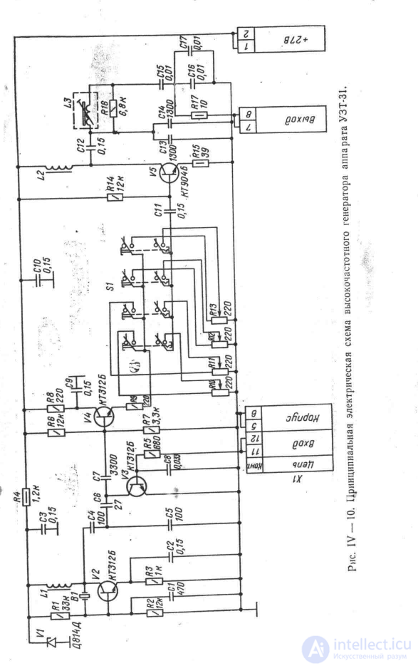
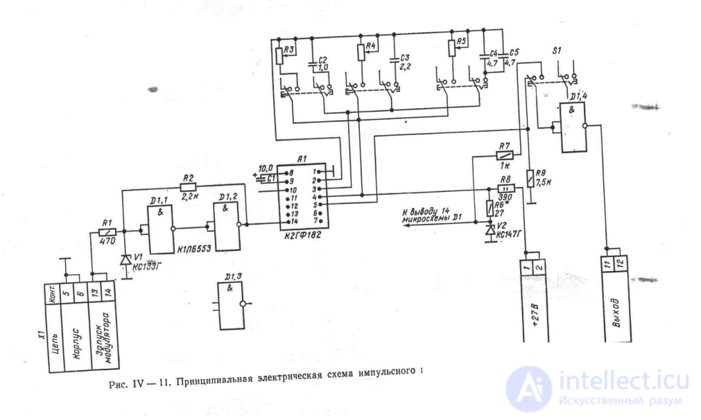
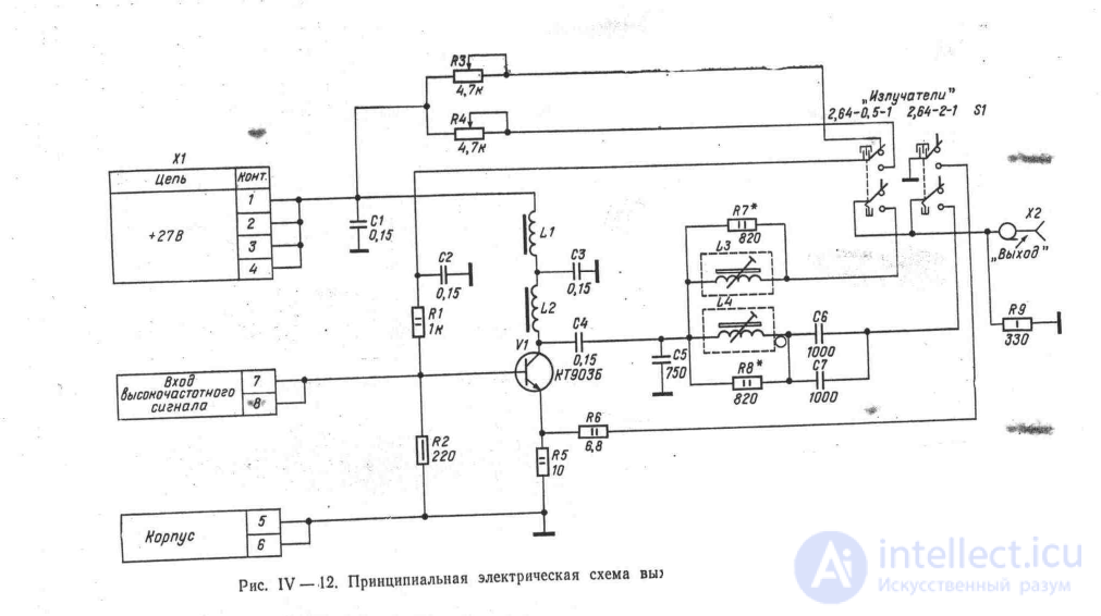
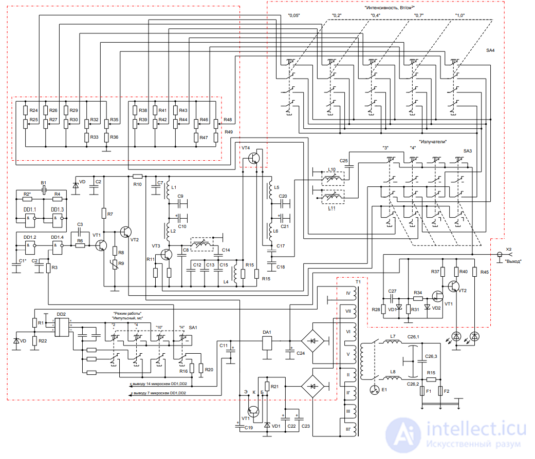 Figure – Schematic electrical diagram of apparatus UZ 51 T – 1.01
On the rear panel are located the «Mains» button of the mains switch, test jacks for checking the operating mode of the apparatus's units, a fuse holder, and a non-removable mains cord.
Fig. IV—13 shows emitter 7 with a working surface of 0.5 cm3 and emitter 8 with a working surface of 2 cm2, connected by coaxial cable 9 to the output of the apparatus.
The apparatus with the housing removed is shown in fig. IV—14. On the left of the chassis is mounted power transformer 1. The procedure timer 2 is attached to the front panel. The printed circuit boards are mounted vertically: board 3 of the power supply unit, board 4 of the modulator, board 5 of the generator, board 6 of the output amplifier. Mains switch 8 and test jacks 9 are mounted on printed circuit board 7.
Due to the use of a frequency of 2.64 MHz in the apparatus, the thickness of the emitter's piezoelectric plate is about 1 mm, and its mechanical strength decreases sharply. Such a plate can be used at an area not exceeding 1 cm2. For this reason, in the emitter with an area of 2 cm2 the piezoelectric transducer consists of two plates connected to each other by like-named electrodes. The plates are joined by the sintering method. The absence of an intermediate adhesive layer, usually used for this purpose, has improved the reproducibility of the resonant frequency of the composite piezoelectric transducer.
The apparatus kit includes a coaxial cable, a case containing two emitters and 3 glass vessels with a capacity of 50 ml for disinfectant, contact and medicinal substances.
Preparation for operation and control of the apparatus during procedures. With the mains switch button on the rear panel of the apparatus set to the released position, plug the mains cord into an outlet with a voltage of 220 V.
Prepare the accessories — fill the vessels in the case with the appropriate liquids (alcohol, vaseline oil, medicinal solution), place cotton wool in the special compartment of the case with a lid.
Connect the emitter to the connecting cable, and the cable to the «Output» jack on the control panel. Having pressed one of the «Emitters» buttons corresponding to the selected emitter, switch on the «Mains» button. In doing so, the indicator lamp above the procedure timer lights up.
To check the operability of the apparatus, turn the emitters working-surface up and pour a few drops of water onto it. Press the «Continuous» button of the «Operating mode» switch and one of the buttons of the «Intensity, W/cm2» switch. Switch on the generator by turning the procedure timer knob clockwise. A light ripple appears on the surface of the water on the emitter (at low intensity) or a small fountain (at high intensity). Oscillations of the water surface, but of smaller amplitude, should also occur when switching to pulsed mode (the «2 ms, 4 ms, 10 ms» buttons of the «Operating mode» switch). It should be kept in mind that during this check the emitter is unloaded, so to avoid its overheating and possible failure, the generator should not be switched on for more than a few seconds.
Turning the timer knob counterclockwise to the zero position switches off the generator. An audible signal should sound at this point.
Having carried out a similar check of the second emitter, make sure that the apparatus is ready for operation.
When carrying out the procedure, connect the selected type of emitter to the cable and set the oscillation mode and intensity prescribed by the physician. Having lubricated the area of the body to be treated with vaseline oil (or a medicinal ointment), apply the working surface of the emitter to it. Then switch on the generator by means of the procedure timer for the time set for the procedure.
When carrying out the procedure (using either the labile or the stable technique), it is necessary to monitor good contact between the emitter and the body. If there is no contact, ultrasonic oscillations do not pass into the body tissue, and the emitter overheats.
At the end of the procedure, the cleaned radiator is placed in a special slot in the case.
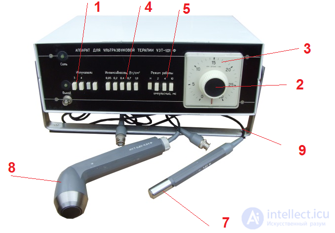
Fig. IV—13. General view of the UZT-31 apparatus.
The number of models of ultrasound diagnostic devices manufactured by various companies is quite large, and in order to navigate this diversity, it is useful to introduce a certain classification of devices.
It is natural to systematize ultrasound apparatuses by functional capabilities and purpose, as well as by technical level and quality of the functions performed.
Bearing in mind functional capabilities and purpose, universal and specialized ultrasound scanners can be distinguished.
Universal devices can be divided into three main types depending on the operating modes used in them.
1. Ultrasound scanners. Devices intended primarily for obtaining a two-dimensional black-and-white acoustic image.
Main operating modes (modes):
- B (or 2D) - two-dimensional image;
- M (or TM) - one-dimensional brightness echogram with time sweep.
Additional modes: B + B, B + M.
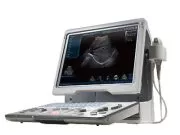
Example of an ultrasound scanner:
 |
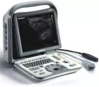 |
| Mindray DP-50 | SonoScape A6 |
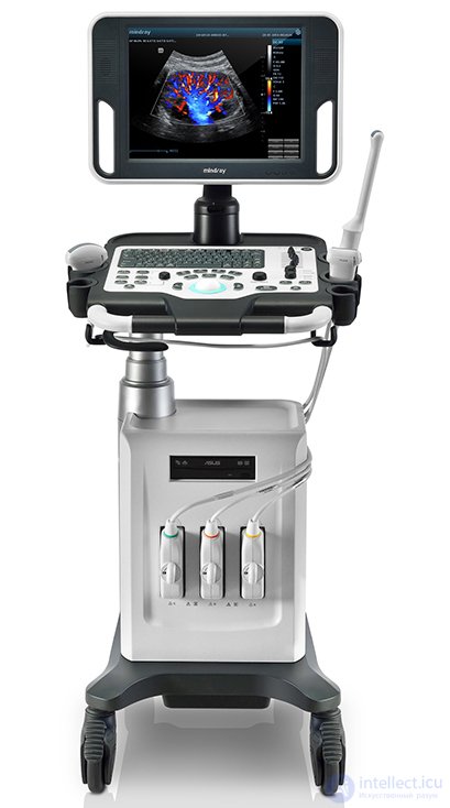
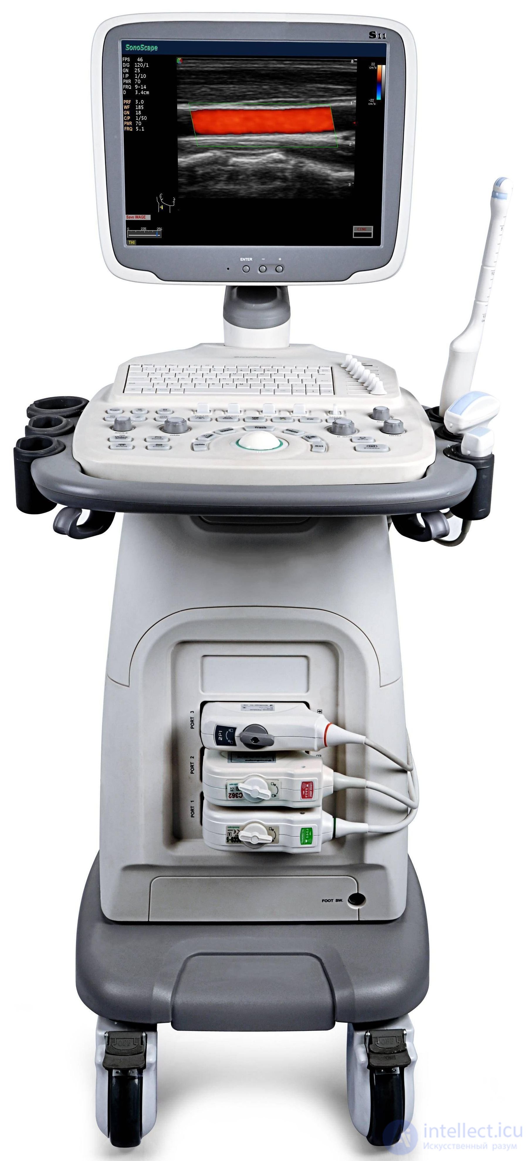
2. Ultrasound apparatuses with spectral Doppler. They are sometimes called duplex devices. They differ from ordinary ultrasound scanners in that they additionally have the ability to assess the spectrum of blood flow velocities using the Doppler method.
Main operating modes:
- B (2D);
- M (TM);
- D - spectral analysis of blood flow velocities using pulsed-wave Doppler (PW) and, in a number of cases, continuous-wave Doppler (CW).
Additional modes: B + B, B + M, B + D (duplex).
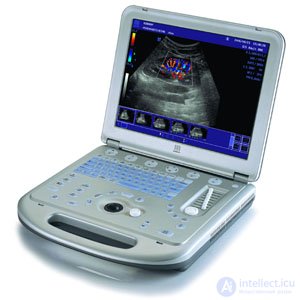
Example of an ultrasound scanner:
 |
 |
 |
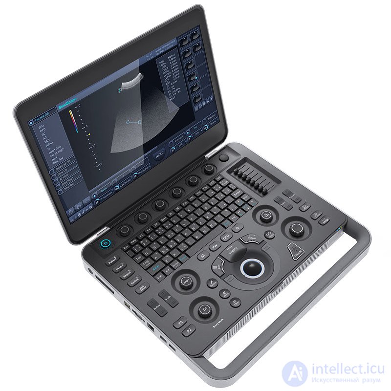 |
| Mindray M5 | Mindray DC-30 | SonoScape S11 | SonoScape S2N |
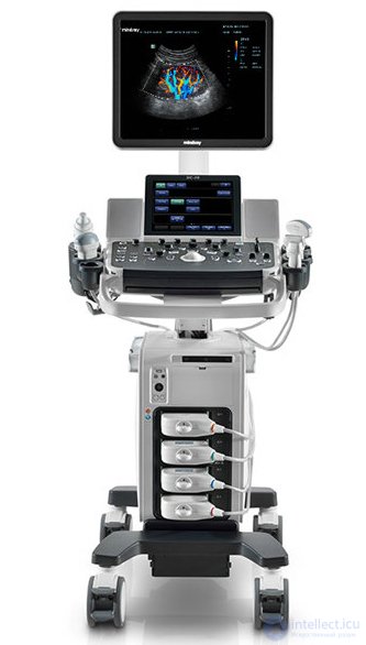
3. Ultrasound systems with color Doppler mapping. They are sometimes called color Doppler devices. These are devices with the maximum number of functions. In addition to the modes available in spectral Doppler scanners, this class of devices has the ability to display a two-dimensional distribution of blood flow velocities, highlighted in color on a two-dimensional grayscale image of tissues.
Main operating modes:
- B (2D);
- M (TM);
- D (PW and CW);
- CFM - color Doppler mapping of blood flow.
Additional modes: B + B, B + M, B + D (duplex), B + D + CFM (triplex).
In addition to those listed, special modes may be used:
- PD - power Doppler;
- TD - tissue Doppler;
- 3D - three-dimensional image;
- tissue (native) harmonic.
The group of specialized ultrasound diagnostic devices includes devices of rather limited medical application.
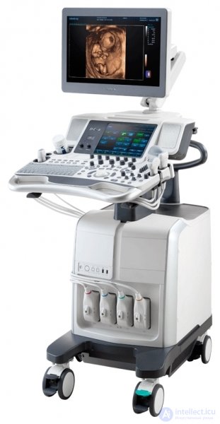
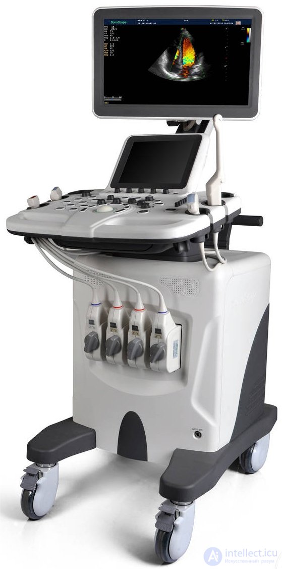
Example of an ultrasound scanner:
 |
 |
 |
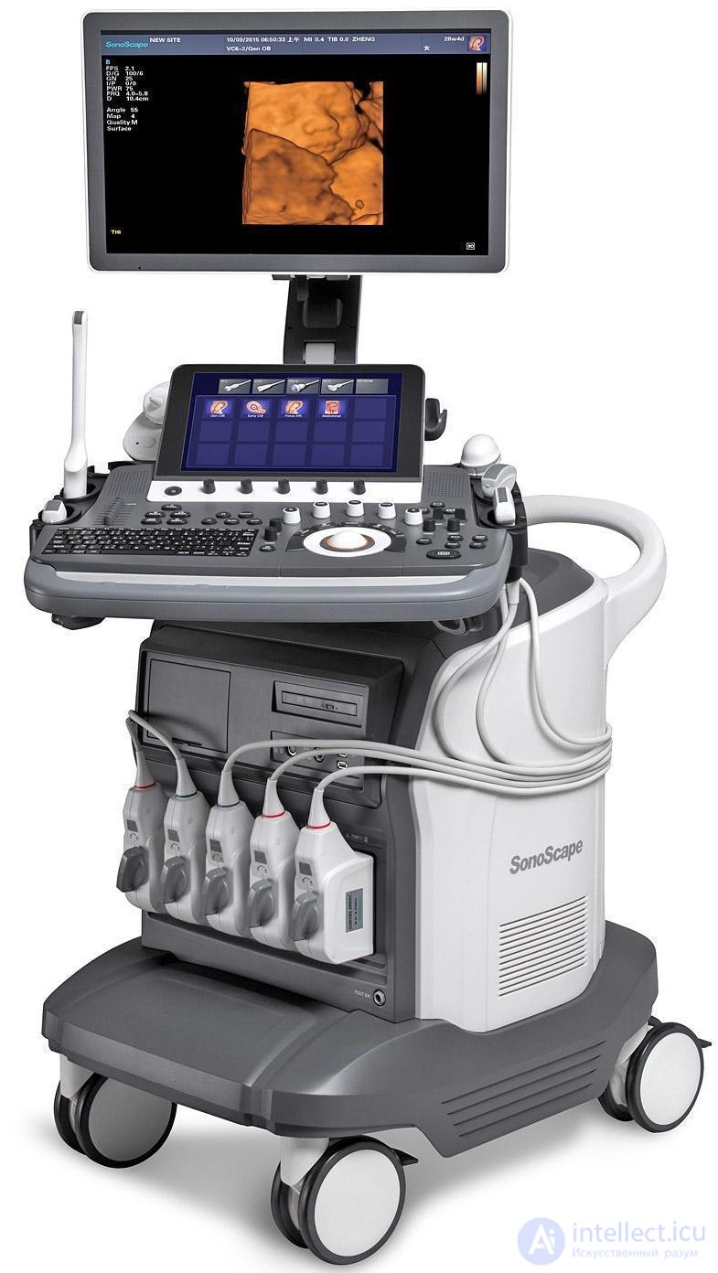 |
| Mindray DC-70 | Mindray DC-8 | SonoScape S30 | SonoScape S40Exp |
Ophthalmological ultrasound devices (echo-ophthalmometers). These are diagnostic devices for visualizing eye structures, using two-dimensional and (or) one-dimensional imaging.
Main operating modes:
- B(2D);
- A - one-dimensional echogram displaying signal amplitudes at various depths.
- D (PW and CW).
Fetal monitors. Ultrasound devices intended for measuring fetal heart rate (FHR) by the Doppler method.
Main operating mode: measurement of fetal FHR and statistical evaluation of FHR change parameters.
Ultrasound apparatuses for intravascular studies. Rarely manufactured devices that use special sensors for invasive examination of vessels, similar to those sometimes included in universal ultrasound scanners.
Main operating mode: B (2D).
Devices for transcranial examinations (echoencephaloscopes). Used for examining the brain (usually through the temporal region of the skull). Main operating modes ALOKA:
- A - one-dimensional amplitude echogram;
- D (PW) - in addition to mode A.
Devices for examining the nasal and frontal sinuses (sinuscopes).
Main operating mode: A - one-dimensional amplitude echogram.
Devices for veterinary medicine. Devices specifically for veterinary medicine are rarely manufactured. Universal devices with specialized sensors for veterinary use are usually used.
Main operating modes:
- -B(2D);
- M (TM).
Modes D and CFM may sometimes be used.
Devices for lithotripsy. These are devices that are part of extracorporeal lithotripters and provide guidance of the shock-wave focus onto calculi, as well as monitoring the process of calculus destruction. Main operating modes:
-B(2D);
-B+B (B/B).
Functional capabilities of the universal and specialized devices listed above are determined not only by their available operating modes, but also by the set of sensors and additional devices that can be connected to the ultrasound apparatus, computational programs, and devices for storing, archiving and recording diagnostic information.
Areas of medical application are mainly determined by the type of sensors working with the ultrasound device and the presence of specialized operating modes.
The quality of the information obtained depends on the technical level of the device - the more complex and advanced the device, the higher the quality of the diagnostic information. As a rule, devices are divided into four groups by technical level:
1) simple devices;
2) mid-class devices;
3) upper-class devices;
4) high-class devices (sometimes called high-end) ALOKA.
Among manufacturers and users of ultrasound diagnostic equipment, there are no agreed criteria for evaluating the class of devices, since there is a very large number of characteristics and parameters by which devices can be compared with each other. Nevertheless, it is possible to assess the level of complexity of the equipment, on which the quality of the information obtained largely depends. One of the main technical parameters determining the level of complexity of an ultrasound scanner is the maximum number of receiving and transmitting channels in the device's electronic unit, since the greater the number of channels, the better the sensitivity and resolution - the main characteristics of ultrasound image quality.
In simple (usually portable) ultrasound apparatuses, the number of transmit-receive channels is no more than 16, in mid-class and upper-class devices 32, 48 and 64. In high-class devices, the number of channels can be more than 64, for example 128, 256, 512 and even more. As a rule, high-class and upper-class ultrasound scanners are devices with color Doppler mapping.
High-class ultrasound apparatuses usually make maximum use of modern digital signal processing capabilities, starting practically from the sensor output. For this reason, such devices are called digital systems or platforms (digital system).
The types of probes and their names are determined by the use of different ultrasound transducers and scanning methods in them. Depending on the type of transducer, the following can be distinguished:
Operating frequency is the most important characteristic of a probe. It is desirable to strive to use probes with a higher frequency, since they provide higher image quality, however it should be remembered that this reduces the depth of examination. Therefore, the choice of probe frequency is determined by the maximum depth of location of the organs and structures of interest to the diagnostician. In a number of cases, when examining obese patients, it is necessary to use probes with a frequency of 2.5 MHz, which have a maximum working depth of " 240 mm, however the resolution when using such probes, and consequently the image quality, is worse than at a frequency of 3.5 MHz. On the other hand, for examining structures located at very shallow depths, probes with a frequency of more than 10 MHz are used.
The appearance of probes is very diverse, but most of the most commonly used types of probes in devices from various companies are similar and differ in insignificant design elements and dimensions. Fig. 1 shows the main types of probes for external examination and their characteristic appearance. The working surface of the probes, which contacts the patient's body, is shown darker in the figure.
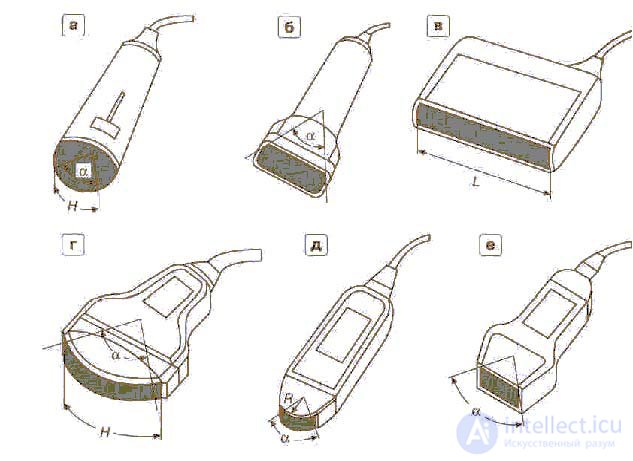
Fig. 1. Main types of probes for external examination, a, b- sector mechanical (a - cardiological, b - with water attachment); c - linear electronic; d - convex; e - microconvex; f - phased array sector.
In sector mechanical probes (fig.1a,1b) the working surface (protective cap) covers the volume in which the single-element or ring-shaped ultrasound transducer, moving through the angle, is located. The volume under the cap is filled with an acoustically transparent liquid to reduce losses during the passage of ultrasound signals. The main characteristic of sector mechanical probes, besides the operating frequency, is the angular size of the scanning sector ?, which is indicated in the probe's marking (sometimes the length of the corresponding arc H of the working surface is additionally given). Marking example: 3,5 MHz/90°.
In linear, convex, microconvex and phased (sector) electronic scanning probes, the working surface coincides with the radiating surface of the ultrasound transducer, which is called the aperture, and is equal to it in size. Characteristic aperture dimensions are used in probe markings and help when choosing a probe.
In linear probes, the characteristic parameter is the aperture length L (fig. 1c), since it is this that determines the width of the rectangular field of view. Marking example for a linear probe: 7,5 MHz/42 mm.
It should be kept in mind that the width of the field of view in a linear probe is always 20-40% less than the aperture length. Thus, if the aperture size indicated is 42 mm, the width of the field of view is no more than 34 mm.
In convex probes the field of view is determined by two characteristic dimensions - the length of the arc H (sometimes its chord), corresponding to the convex working part, and the angular size of the scanning sector a in degrees (fig. 1d). Marking example for a convex probe: 3,5 MHz/60°/60 mm. Less often, the radius R of curvature of the working surface is used for marking, for example: 3,5 MHz/ 60R (radius - 60 mm).
In microconvex probes, the characteristic parameter is the R - radius of curvature of the working surface (aperture); sometimes the arc angle a, determining the angular size of the viewing sector, is additionally given (fig. 1e). Marking example: 3,5 MHz/20 R (radius - 20 mm).
For a phased array sector probe, the angular size of the electronic scanning sector in degrees is given. Marking example: 3,5 MHz/90°.
The probes shown in fig. 1 are used for external examination. In addition to them, there is a large number of intracavitary and highly specialized probes, which use the same types of ultrasound transducers.
It is advisable to introduce a classification of probes by areas of medical application.
1. Universal probes for external examination [abdominal probe). Universal probes are used for examining the abdominal region and pelvic organs in adults and children.
Convex probes with an operating frequency of 3,5 MHz (for adults) or 5 MHz (for pediatrics), less often 2,5 MHz (for deeply located organs), are mainly used as universal probes. The angular size of the scanning sector: 40°-90° (less often - up to 115°), the arc length of the working surface - 36-72 mm.
Until recently, linear probes with an operating frequency of 3,5 (less often 5) MHz and a working part length from 64 to 125 mm were widely used as universal probes (larger sizes were especially popular in obstetrics for fetal observation). Now convex probes are preferred. In the basic configuration of almost any device, a convex probe of 3,5 MHz/60°/60 mm or one with similar characteristics is most often specified.
Example: UST-934N-3,5 ; UST-979-3,5 ; UST-9123; UST-9126.
2. Probes for superficially located organs (small parts probe). Used for examining shallowly located small organs and structures (for example, the thyroid gland, peripheral vessels, joints, etc.).
Operating frequency - 7,5 MHz, sometimes 5 or 10 MHz. Probe type - linear, 29-50 mm in size, less often convex, microconvex or sector mechanical with a water attachment (fig. 1b) with an arc length of 25-48 mm.
Example: UST-5512U-7,5 ; UST-5710-7,5 ; UST-5545.
3. Cardiac probes (cardiac probe). Sector-type probes are used for examining the heart, which is related to the specific feature of observation through the intercostal space. Mechanical scanning probes (single-element or with a ring array) and phased electronic probes are used. Operating frequency - 3,5 or 5 MHz.
Sometimes microconvex probes with a frequency of 3,5 (5) MHz and a radius of curvature from 10 to 20 mm are used for cardiology.
Recently, a transesophageal probe has been used for cardiac observation in high-class devices with color Doppler mapping.
Example: UST-944B-3,5 ; UST-978-3,5 ; UST-5266-3,5; UST-5299; UST-5293; UST-5297; UST-5280-5; UST-52101; UST-5280-5.
4. Probes for pediatrics (pediatric probes). The same probes as for adults are used in pediatrics, but only with a higher frequency (5 or 7,5 MHz), which makes it possible to obtain higher image quality. This is possible due to the small size of the patients. Special probes are also used in pediatrics. For example, for examining the brain of newborns through the fontanelle, a sector or microconvex probe with a frequency of 5 or 6 MHz is used (neonatal probe).
Example: UST-935N-5 ; UST-9103-5 ; UST-992-5; UST-5294-5.
5. Intracavitary probes (intracavitary probes). There is a wide variety of intracavitary probes, which differ from each other in areas of medical application.
6. Biopsy or puncture probes (biopsy or puncture probes). Used for precise guidance of biopsy or puncture needles. For this purpose, probes are specially designed in which the needle can pass through a hole (or slit) in the working surface (aperture). It should be said that transvaginal and transrectal probes are very often designed so as to enable biopsy, and therefore can also be considered biopsy probes.
Due to the technological complexity of manufacturing specialized biopsy probes and, consequently, their higher cost, most companies use so-called biopsy adapters - devices for guiding biopsy needles. The adapter can be rigidly attached to the body of an ordinary probe and is removable.
Example: UST-9113P-3,5; UST-5045P-3,5.
7. Highly specialized probes. Most of the probes discussed above have a fairly wide range of applications. At the same time, a group of narrow-application probes can be distinguished, and they deserve special mention.
8. Broadband and multi-frequency probes. Broadband probes are increasingly used in modern complex devices. These probes are structurally designed similarly to the ordinary probes discussed above, and differ from them in that they use a broadband ultrasound transducer, i.e. a probe with a wide band of operating frequencies.
In broadband probes, the relative bandwidth can exceed 1, which leads to a significant improvement in resolution, especially in the near and mid zones by depth. At greater depths, the bandwidth expansion has less effect due to the stronger attenuation with depth of the high-frequency components of the signal.
In some devices, switching of the operating frequencies of a broadband probe is used - in this case the probe operates at various switchable central frequencies depending on the depth of interest to the researcher. The probe is in this case called multi-frequency, and the relative bandwidth at each of the frequencies is the same as in an ordinary probe. Two-frequency and three-frequency probes are most often used. Typical examples of frequency combinations in two-frequency probes: 3-5, 4-7 or 5-10 MHz.
9. Doppler probes. These probes are used only for obtaining information about the velocity or spectrum of blood flow velocities in vessels.
10. Probes for obtaining three-dimensional images. Special probes for obtaining 3D (three-dimensional) images are rarely used. Ordinary two-dimensional image probes are more often used together with special devices that provide scanning along the third coordinate.
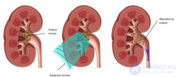
Lithotripsy is a non-invasive procedure involving the physical destruction of hardened formations, such as kidney stones, bezoars or gallstones. The term comes from the Greek words meaning "stone-breaking".
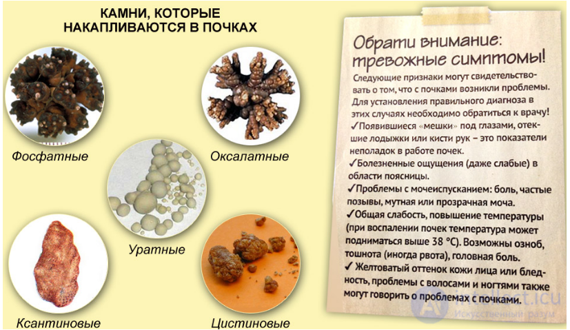
Kidney stones can cause the patient enormous discomfort while they pass through the urinary tract. Ultimately, these stones can lead to loss of function of the affected kidney. Surgical operation (dichotomy), can be used to remove the stones, however this procedure involves all the risks, complications, discomfort and loss of working capacity that are inherent in most surgical interventions. In contrast, lithotripsy (stone crushing) is among the surgical procedures performed non-invasively, or with minimal invasive surgical intervention, and therefore does not have such risks and complications. This procedure consists of crushing the stone in vivo so that it passes through the urinary tract in the form of small particles, the elimination of which is not accompanied by significant discomfort and loss of working capacity (Bush, Branneb, 1988).
In percutaneous lithotripsy, a probe is inserted through a small incision to the site where the kidney stone is located, with the process of probe insertion monitored using X-ray fluoroscopy. The crushing process itself is carried out either using a mechanical shock wave caused by a controlled electrical discharge at the tip of the probe, or using a transducer generating ultrasound waves built into the probe. The crushed stones are removed from the kidney in pieces using a special device on the probe. Some of them pass out on their own through the urinary tract.
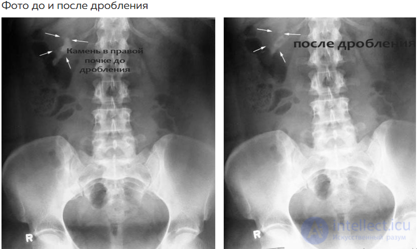
Extracorporeal shock-wave lithotripsy is a completely non-invasive procedure that can be used to remove kidney stones. Fig. 15 shows the main structural elements of the devices used to perform such procedures. A series of mechanical shock waves is generated at the focus of an elliptical reflector in such a way that they concentrate at the conjugate focus a few centimeters from the reflector. Both the reflector and the patient are immersed in desalinated degassed water so that the patient can be moved until the stone reaches the point of concentration of the shock waves. Correct positioning of the patient is very important, so a two-axis X-ray apparatus is used for positioning, which also serves to monitor the process of stone destruction. A high-voltage pulse (about 20 kV) is applied to the spark gap, in which the discharge causes a shock wave. This wave propagates through the water to the conjugate focus. The patient is placed on a special movable platform, which allows their position to be changed with high precision, while the operator monitors the location of the stone on the monitor of the two-axis X-ray apparatus. Once the patient is in the required position, shock waves are generated in the spark gap by repeated discharge. Up to 2000 discharges may be required to break a kidney stone 1—2 mm in diameter into small fragments that can pass painlessly through the urinary tract.
After such treatment, most patients can return to normal life after 2 days. This is significantly less than is required for recovery after surgical stone removal. Therefore, although such an apparatus is an expensive and complex device to operate, its advantages are obvious, both from the point of view of patients and from the point of view of the efficiency of medical institutions.
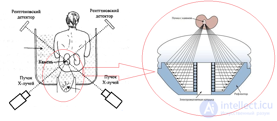
Fig. 15 Extracorporeal shock-wave lithotripsy.
To ensure that the stone is at the focus of the elliptical reflector of the shock-wave generator, a two-axis X-ray apparatus is used (X-rays = roentgen rays).

Comments