
Lecture
Every year, cases of failure to operate or non-selective operation of protective devices in secondary electrical circuits are recorded in the power supply systems of industrial enterprises. A significant proportion of such cases are accompanied by damage to the main equipment. One of the causes of failures is insufficient sensitivity of the protective devices. When these installations were designed, the complex of factors affecting metallic and arc short-circuit currents was not sufficiently taken into account. As a result, overestimated calculated values of short-circuit currents were used for selecting protective devices. To ensure reliable operation of the elements of relay protection and automation systems, it is necessary to diagnose the DC auxiliary power electrical installations. To solve this problem, the "Electric Power Stations" department of MEI, together with OJSC "Mosenergo", created a software and hardware complex (SHC), which includes:
- the GUCHOICE program "Selectivity map of circuit breakers and fuses";
- the GUDCSETS program "Short circuits in DC electrical installations with voltage up to 1 kV";
- a specialized device for experimental determination of short-circuit currents (SCDD).
The GUCHOICE program allows analysis of the selectivity of protective devices based on time-current characteristics. The basis of the program is a database of time-current characteristics of domestically produced circuit breakers and fuse links. To check selectivity, protective devices corresponding to those installed in a specific network — for example, in the supply busbar (SB) ring of circuit breaker closing electromagnets — are selected from the database according to rated parameters. Their time-current characteristics are plotted on the computer screen in a unified named logarithmic coordinate system. The protective characteristics of circuit breakers with adjustment, for example of the A3793C series, are plotted taking into account the settings established during commissioning. It is also possible to take ambient temperature into account. The program allows plotting the tripping characteristics of six protective devices in the same coordinate axes (Figure 6.1). If non-selectivity is detected, a protective device with a characteristic satisfying the selectivity requirement can be selected from the database.
The GUDCSETS program allows calculation of short-circuit currents in order to check the sensitivity of protection devices. The program fully complies with GOST recommendations. During calculations, the following are comprehensively taken into account:
- thermal decay of current, caused by changes in cable resistance due to non-adiabatic heating by short-circuit currents (taking into account heat transfer to the insulation of current-carrying conductors);
- the influence of ambient temperature and current load on cable resistance;
- the possibility of feed-in from DC motors;
- the resistance of circuit breaker trip units, contact connections and fuse links;
- the non-linearity of the current-voltage characteristic of the battery and the external current-voltage characteristics of charging/float-charging units;
- the non-linear resistance of the electric arc.
Preparation of the calculation scheme and its subsequent editing are carried out interactively using a database of standard graphic symbols for elements of DC auxiliary power electrical installations (Figure 6.4).
Parameterization of scheme elements can be performed manually or by using the program's database, which contains the information necessary for calculations about batteries, disconnect switches, cables, fuses, circuit breaker trip units, etc.
The combined use of the GUDCSETS and GUCHOICE programs allows determining the magnitude and duration of voltage reduction at nodes of DC auxiliary power electrical installations when various types of short circuits are cleared at different electrical distances, which is important for assessing the operability of DC consumers.
The complex includes a portable computer and a power unit. The diagnostic complex ensures simultaneous performance of both calculation work and obtaining short-circuit current values experimentally. Experimental current values make it possible to take into account the actual condition of the battery and the contact connections of the short-circuited circuit.
The SCDD power unit is computer-controlled and provides for the creation of load pulses of a specified magnitude and duration. The load resistance can be varied from 25 to 2500 mOhm, and the pulse duration from 2 to 10000 ms. The transient processes created by the power unit are recorded using an analog-to-digital converter and processed by the computer to obtain the necessary diagnostic information. The technical base of the SCDD is universal and allows for expansion of its functional capabilities, up to and including use in the diagnostics of AC electrical installations with a voltage of 0.4 kV.
The most complete information about the technical condition of the auxiliary power circuits can only be provided by combined calculation and experimental studies. Experimental studies conducted separately do not give an idea of the possible boundaries of short-circuit current variation. It is known that the sensitivity of protective devices should be checked using the minimum possible current values, while checking selectivity generally also requires knowledge of the maximum possible current values. Maximum possible current values are needed to check the switching capacity of devices and to check cables for thermal resistance and fire safety. To experimentally determine the boundary current values, it would be necessary to reproduce various options of repair and post-emergency schemes on a live electrical installation, switch charging/float-charging devices on and off, simulate arc short circuits, create sustained short circuits to heat cables to temperatures corresponding to such short circuits, and discharge the battery to the level specified by operating rules.
The use of the GUCHOICE program allows analysis of the characteristics of protective devices, identification of the threat of their non-selective operation during short circuits, and taking necessary measures. Comparison of the calculated short-circuit current values obtained using the GUDCSETS program with the experimental data obtained using the SCDD makes it possible to assess the serviceability of many elements of the DC auxiliary power electrical installation. Usually, a sign of a fault in the elements of the auxiliary power circuits is a difference exceeding 10% between the calculated value of the metallic short-circuit current and its value obtained experimentally. Comparison of the calculated and experimental short-circuit current values makes it possible to detect dangerous deterioration of battery condition. Among batteries that have been in operation for several years, batteries are identified with a level of short-circuit currents significantly lower compared to new batteries. As a rule, such batteries cannot ensure reliable operation of protective devices.
Comparison of the calculated and measured short-circuit current values makes it possible to check the quality of electrical connections of panels and secondary circuits. Contact defects caused by weakening of the steel ring spring on the contact post of a fuse or disconnect switch, or by a loosened electrical clamp bolt, manifest themselves only when currents flow that are comparable in magnitude to short-circuit current values. Such defects cause a reduction of 25% or more in the short-circuit current value determined experimentally compared to the calculated value.
The ability to adjust the magnitude and duration of the current pulses created by the SCDD makes it possible to use it for testing circuit breakers with trip unit settings up to 2500 A without removing them from panels and switchboards. In this case, the source of the test current is the standby battery.
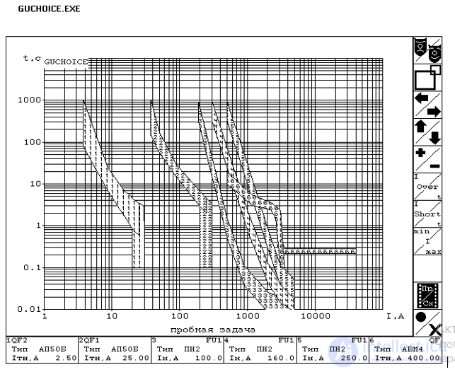
Figure 6.1 - Checking the selectivity of protective devices using the GUCHOICE program
The CA 8350 power network parameter analyzer is a representative of analyzers designed for measuring power parameters of electrical networks with interference. This is a three-phase analyzer, fully controlled via a graphical interface. All types of programming and output of measurement data to the display are performed using a touch screen using the Windows operating system context. The basic configuration automatically includes a fast Fourier transform function and an oscilloscope mode. The computing unit is an INTEL Pentium 500 processor. The device can measure current and voltage parameters, active and reactive power, spectral analysis of harmonic components up to the 50th harmonic, analysis of the system with positive phase sequence, negative phase sequence and zero phase sequence. The analyzer can be used to plot vector diagrams of voltages and currents, and to record short circuits.
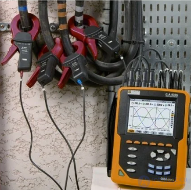
The 3-phase Qualistar CA 8332 and CA 8334 power quality analyzers are designed for the energy and operational services of industrial enterprises and instantly provide a picture of the main characteristics of the power network, which is supplemented by calculated parameters and numerous processing functions (Figure 6.2).
|
Figure 6.2 - Qualistar CA 8332 power quality analyzers |
The main measured parameters are currents, voltages, frequency, active, reactive and apparent power of an individual phase and of all phases, active, reactive, received and transmitted energy, apparent energy, voltage, current and power of harmonics up to the 50th order.
Additional functions of the device:
|
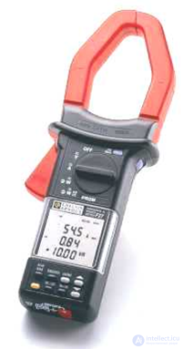
Figure 6.3 - F27 current clamp meter
|
- graphical presentation of data;
- alarm signals, display of transient processes;
- recording, dating and characterization of disturbances (overloads, dips, dropouts, etc.);
- data storage;
- immediate printout of the screen image to a printer.
Main calculated parameters:
- neutral current;
- phase current and voltage imbalance;
- total harmonic distortion factor.
The multifunctional F27 current clamp meter - power and harmonics meter is designed for testing, operational monitoring and analysis of power quality in AC (sinusoidal and non-sinusoidal) and DC networks. The measured parameters are currents and voltages, frequency, active, reactive and apparent power in 1- and 3-phase networks, harmonic factor, and values of individual harmonics up to the 25th order.
|
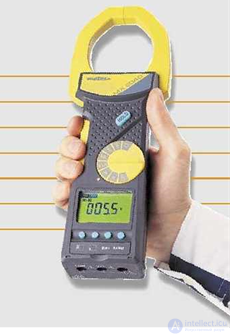
Figure 6.4 - MX 2040 current clamp meter |
The RS232 optical output and software are used to print out measurement results on a printer and to process them (Figure 6.3).
Universal current clamp meters MX 2040 and MX 240 are designed for measuring DC and AC voltages and currents in single-phase and three-phase systems, as well as power, energy, and frequency. The current clamp meters have a 3-phase input and allow the following functions:
- measurement of power factor and determination of compensating capacitance;
- transmission of an analog signal via adapters;
- transmission and processing of a data stream on a computer;
- display of two parameters to speed up measurements (Figure 6.4).
Automated diagnostic system ASK "Test" is designed to monitor the parameters of relays and relay units of automation and telemechanics under the conditions of a repair and maintenance workshop.
Areas of application of ASK "Test":
- verification of correct installation of relay units;
- determination of electrical and time parameters of relays included in relay units: pickup voltage, dropout voltage, dropout delay time, overtravel voltage for polarized relays, dropout time;
- determination of electrical and time parameters of relays: pickup voltage, dropout voltage, pickup delay time, dropout delay time, non-simultaneity of pickup, winding resistance, contact resistance.
The architecture of the diagnostic system is designed so that up to four measurement units, operating independently of each other, can be connected to a single computer. The total number of control outputs of such a system is 576.
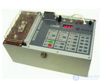
Saturn-M test equipment is designed for testing and adjusting circuit breakers with thermal and electromagnetic trip units for 220-380 V connections at a frequency of 50 Hz, as well as for testing the characteristics of relay protection devices for 6-35 kV connections and evaluating the short-circuit (SC) current of the phase-to-neutral circuit of 380 V connections and the SC current on 380 V busbars (Figure 6.5).
The test equipment provides:
|
Figure 6.5 - Complete "Saturn-M" test equipment |
- the ability to test relay protection and automation equipment for 6-35 kV connections with secondary current together with a load transformer, whereby it is used to regulate the primary current of the transformer, measure the RMS value of the secondary current, set a given duration of current flow, and measure the protection pickup time;
- the ability to test the characteristics of relay protection of electrical connections for 6-35 kV with primary current without a load transformer from a 380/220 V network at current values up to 2000 A, and with a load transformer at current values up to 12000 A;
- the ability to evaluate the short-circuit (SC) current of the phase-to-neutral or phase-to-phase circuit of 380 V connections for selecting the characteristics of relay protection, fuse links, and circuit breakers.
The range of current regulation and measurement in the circuit without a load transformer is 10..2000 A.
The range of primary current regulation in the circuit with a load transformer is 0.5..300 A.
The range of current measurement with a built-in current transformer is 10..2500 A, with an external current transformer - 0.1..99.99 kA.
The range of setting and measuring the duration of current flow and the device tripping time is 0.01..99.99 s.
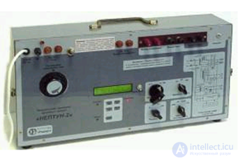
Neptun complete test equipment for testing simple protection devices is designed for testing simple relay protection and automation devices such as current relays, voltage relays, and time relays directly at power facilities (Figure 6.6).
The devices are powered from a single-phase AC network with a frequency of 50 Hz and a voltage of 220 V and perform the following main functions:
- generation of a sinusoidal current of adjustable magnitude;
- generation of a sinusoidal or DC output voltage of adjustable magnitude;
|
Figure 6.6 – Neptun complete test equipment |
- measurement of the generated current and voltage values;
- measurement of time parameters.
The "Neptun" device produces the following output signals:
- AC voltage with a frequency of 50 Hz from 0 to 240 V or from 0 to 25 V at a current of up to 2 A with smooth regulation (briefly - up to 5 A);
- DC voltage from 0 to 320 V or from 0 to 35 V at a current of up to 2 A with smooth regulation;
- AC current with a frequency of 50 Hz from 0 to 10 A (25 V max.), from 0 to 20 A (12 V max.), or from 0 to 40 A (6 V max.) with smooth regulation.
The "Neptun" device allows measuring the delivered active power. The power measurement range is from 0 to 1000 W.
The "Neptun-2" device features higher output power - the maximum continuous current of the voltage channel is increased to 5 A, and the AC current channel has the following subranges: 0 - 25 A (50 V max.), 0 - 50 A (25 V max.), and 0 - 100 A (12 V max.). The output power measurement range is also expanded to 2000 W.
The RETOM-41M test device is designed for automated testing and commissioning of relay protection and automation devices of all generations:
- modern microprocessor-based relays and complex protection systems;
- domestic semiconductor relay protection and automation devices;
- the entire range of electromechanical panels and protection and automation kits;
- domestic and foreign fault location devices;
- emergency control panels and telemetry circuits;
- electricity meters.
The test device is used in the commissioning and operation of relay protection and automation devices with issuance of a test report.
The device contains 3 current sources, which can operate in the following modes:
- three-phase mode 3 x 0...20 A, 3 x 250 VA;
- single-phase mode 1 x 0...60 A; 1 x 750 VA;
- DC mode 1 x 0...20 A; 1 x 250 W;
- three-phase mode 3 x 0...120 V, 3 x 60 VA;
- single-phase mode 1 x 0...240 V, 1 x 120 VA;
- DC mode 1 x 0...320 V, 1 x 40 W;
Technical data of RETOM-41M:
- phase adjustment range in the current and voltage channels 0...360 º, minimum phase adjustment step 0.1º, phase setting error ± 0.05 %;
Review questions

Comments