
Lecture
Contents
1. Maximum TV repair complexity category.
This category includes TV repairs involving the elimination of atypical and hidden TV defects. Depending on the brand, model, and type of breakdown, the TV fault may be obvious. But often it is quite difficult to determine the root cause of a TV fault during diagnostics, which is accompanied by replacing the identified non-working board components whose defect caused the TV fault. For example, during repair of the TV motherboard. TV repair is a painstaking process requiring the technician to have logical thinking and jeweler's precision. The mainboard is the brain of the TV, the main control element of the TV system. Therefore TV mainboard repair can be classified as maximum complexity. A TV service center's arsenal may include a perfectly good used mainboard, for which the TV service will, of course, provide a warranty if repairing the mainboard is not practical and a decision is made to replace the main board. A large number of LCD TVs with damaged screens, often new ones, serve as donors of TV parts.
The maximum complexity category primarily includes TV matrix (panel) repair.
LCD matrix repair is complex work requiring specific knowledge in the field of TV repair. The matrix repair process, if possible at all, has certain subtleties. Not every TV technician, even a highly qualified one, can perform TV matrix repair.
Sometimes, in order to find and eliminate the key TV fault, the technician needs to perform a whole series of preliminary measurements and eliminations, and then replace the faulty board component found. The needed part may not be in stock. In this case, the TV service specialist will select a suitable part matching the parameters. If a TV repair started at home turns out to be complex, and the technician needs more than 2 hours to carry out the TV repair or requires special equipment, then the TV repair, as a rule, continues at the TV service center.
2. Medium TV repair complexity category.
Most TV breakdowns fall into the medium complexity category. In this case, the technician may need 1.5 - 2 hours for an on-site TV repair. Such repair is often associated with a standard TV fault.
Philips LCD TV repair can be difficult due to design features, even if the fault is not very complex. Take, for example, repairing the power supply of a Philips LCD TV. This TV fault is simple, but getting to the PSU during the repair of a Philips LCD TV is a real problem. The disassembly-reassembly stage during a technically simple TV repair can drag on due to the presence of multiple fragile plastic latches or an LCD panel glued to the frame of the housing. Technicians encounter such problems when repairing MYSTERY and SUPRA TVs.
And in the conditions of an on-site TV repair, this process will be even more difficult.
Inside an old CRT TV there will inevitably be a blanket of decade-old dusty deposits. And under normal conditions, a TV needs stable cooling. TV software configuration (flashing/firmware update of an LED TV), as well as fine-tuning an LCD TV using the service menu, can be classified as medium complexity TV repair.
3. Simple TV repair complexity category.
Fixing a mechanical TV breakdown. For example, soldering the antenna jack or quickly replacing an obviously failed TV unit. Simple power supply repair, for example, replacing bulged capacitors or a diode bridge, which by professional standards can be classified as simple and elementary. Such technician's work involves contact soldering, mainly in the repair of LCD TVs older than 7 years, as well as in the repair of CRT TVs, which are still fairly common and work quite well. As a rule, a simple on-site TV repair requires up to 1 hour of the technician's working time.
After completing the work, the technician provides the client with a report on the TV or monitor repair performed, and issues a warranty card. The services are completely transparent, understandable and open to the client.
Compare your TV's fault with examples from the practice of TV repair in Chelyabinsk. The website provides a description of the most typical TV breakdowns and their causes. The concept of repairing LCD and plasma TVs of various models is set out. A TV service specialist will answer all your questions regarding TV repair.
Troubleshooting in TVs, monitors and TV tuners can be a complex process requiring experience and knowledge in electronics and repair. However, if you have a basic understanding of electronic components and circuits, you can use the following general algorithm to find faults:
Check the connection and power source:
Visually check for visible damage:
Perform basic diagnostics:
Check the input and output ports:
Examine the circuit and device blocks:
Use measuring instruments:
Check and replace components:
Perform testing:
Retesting and final check:
Document the results:
It is important to remember that safety should be your priority when working with electronics. Before starting the repair, make sure the device is disconnected from the power source, and take all necessary precautions to avoid electric shock. If you are not confident in your skills, it is recommended to contact an experienced electronics repair specialist.
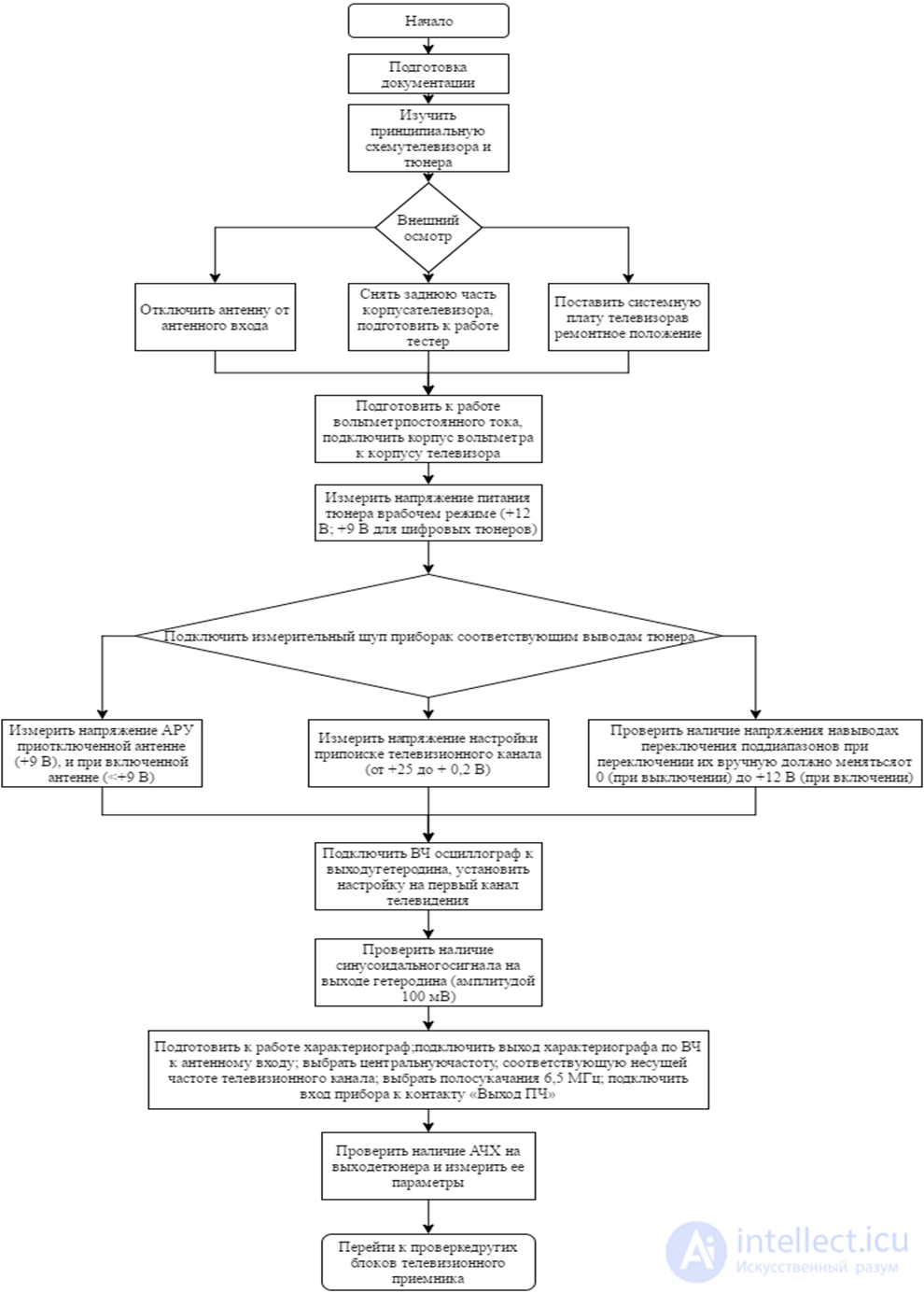
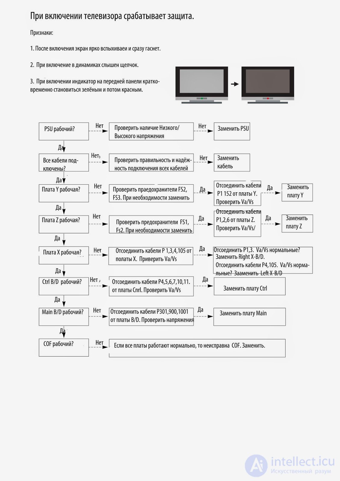
Finding a defect is much harder than fixing it, especially for a beginner technician. The universal method proposed by the author of the article will allow you to quickly and effectively diagnose a modern TV.
WHERE TO START THE REPAIR?
When repairing TV receivers, there are situations when the TV does not turn on and shows no signs of life. This significantly complicates locating the defect, especially considering that imported equipment often has to be repaired without circuit diagrams. The technician faces the task of identifying the fault and eliminating it with the least amount of time and effort. To do this, it is necessary to follow a certain fault-finding methodology.
If a repair shop or a private technician values their reputation, it is necessary to start by cleaning the unit. Armed with a soft brush and a vacuum cleaner, one should clean the inner surface of the housing, the surface of the CRT, and the board of the TV receiver. After thorough cleaning, an external inspection of the board and its components is carried out. Sometimes the location of the fault can be determined immediately by swollen or burst capacitors, by burnt resistors, or by transistors and microchips burned all the way through. It happens that after cleaning the dust off the CRT, instead of a transparent bulb we see a milky-white inner surface (loss of vacuum).
Much more often, visual inspection does not reveal external signs of faulty parts. And then the question arises - where to start?
| Breakdown | Cause of the breakdown | ||
|---|---|---|---|
| Bands or dim screen. | The most likely cause lies in the cable or the scan unit. | ||
| TV does not turn on or there is no picture. | If you use a CRT TV, the likely fault will be in the power supply or scan units. Digital TVs may not turn on due to faults in the power supply and digital units. | ||
| TV shows nothing. | Possibly, if you have a CRT TV, the scan unit has broken, and if it's a digital one, then the inverter unit or the screen itself. | ||
| TV does not "pick up" channels. | The least problematic option is improper installation or operation of the antenna and cable. There is also a chance of a defect occurring in the RF channel unit. | ||
| The TV shows channels with interference. | Obviously the problem lies in the incoming signal. Perhaps the settings were made incorrectly, the antenna cable is connected incorrectly, or it has broken. | ||
| The jack is damaged. | The plug's serviceability is diagnosed and, if necessary, replaced. |
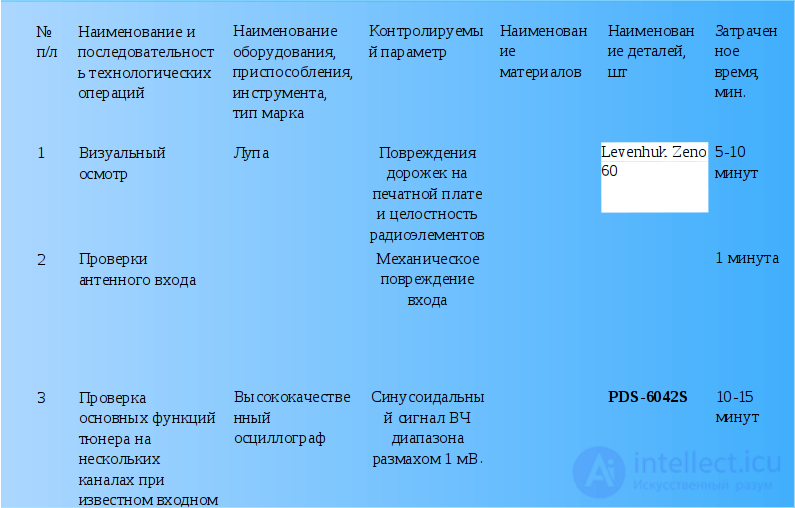
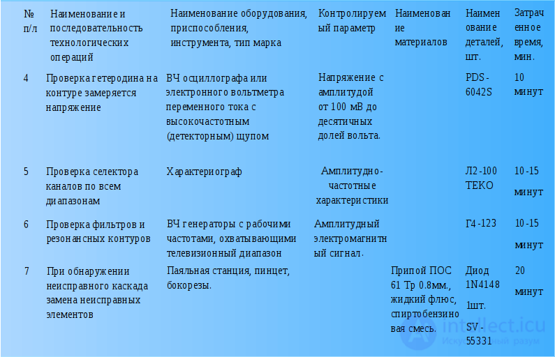
It is most advisable to start the repair by checking the PSU's serviceability. To do this, we disconnect the load (the line output stage) and connect an incandescent lamp, 220 V, 60...100 W, in its place.
Usually the line scan supply voltage is 110...150 V depending on the CRT size. Looking at the secondary circuits, on the board next to the PSU's switching transformer, we find the filter capacitor, which most often has a capacitance of 47...100 uF and a rated voltage of about 160 V. Next to the filter is the line scan supply voltage rectifier. After the filter, the voltage goes to the output stage through a choke, a limiting resistor, or a fuse, and sometimes there is simply a jumper on the board. By unsoldering this element, we will disconnect the PSU's output stage from the line scan stage. In parallel with the capacitor, we connect an incandescent lamp - a load simulator.
On first power-up, the PSU's switching transistor may fail due to a fault in the surrounding components. To prevent this from happening, it is better to power up the PSU through one more incandescent lamp with a power of 100...150 W, used as a fuse and connected in place of the desoldered component. If there are faulty elements in the circuit and the current draw is high, the lamp will light up, and the entire voltage will drop across it. In such a situation, it is necessary, first of all, to check the input circuits, the mains rectifier, the filter capacitor, and the PSU's power transistor. If, upon power-up, the lamp lit and immediately went out, or began to glow weakly, then it can be assumed that the PSU is functional, and it is better to carry out further adjustment without the lamp.
Having switched on the PSU, measure the voltage across the load. Carefully look at the board to see if there is an output voltage adjustment resistor near the PSU. Usually there is a label next to it indicating the voltage value (110...150 V).
If there are no such elements on the board, pay attention to the presence of test points. Sometimes the supply voltage value is indicated near the terminal of the line transformer's primary winding. If the CRT diagonal is 20...21", the voltage should be in the range 110...130 V, and for a CRT size of 25...29" the supply voltage range is usually 130...150 V.
If the supply voltage is higher than the specified values, you need to check the integrity of the elements in the PSU's primary circuit and the feedback circuit, which serves to set and stabilize the output voltage. Electrolytic capacitors should also be checked. When they dry out, their capacitance decreases significantly, which leads to improper circuit operation and an increase in secondary voltages.
For example, in the Akai CT2107D TV, when the electrolytic capacitor C911 (47 uF, 50 V) dries out, the voltage in the secondary circuit can rise from 115 V to as much as 210 V.
If the voltages are too low, you need to check the secondary circuits for shorts or large leakages, the integrity of the protective diodes R2K, R2M in the line scan supply circuit, and the 33 V protective diodes in the field scan supply circuit.
For example, in the Gold Star CKT 2190 TV, when the line scan supply filter capacitor (33 uF, 160 V) was faulty and had a large leakage current, the output voltage was about 30 V instead of 115 V.
In the Funai TV-2000A MK7 TV, the R2M protective diode was punctured, which caused the protection to trip and the TV would not turn on; in the Funai TV-1400 MK10, a breakdown of the 33 V protective diode in the field scan supply circuit also caused the protection to trip.
Having dealt with the PSU and made sure it is functional, we restore the connection in the line scan supply circuit, having first removed the lamp that was used in place of the load.
For the TV's first power-up, it is advisable to install an incandescent lamp used in place of a fuse.
If the line scan output stage is functional, the lamp will light up for a few seconds when switched on and then go out, or will glow weakly.
If, when switched on, the lamp flashed and continues to burn, you need to make sure the line scan output transistor is serviceable. If the transistor is serviceable but there is no high voltage, check for the presence of control pulses at the base of the line scan output transistor. If the pulses are present and all voltages are normal, it can be assumed that the line transformer is faulty.
Sometimes this is immediately apparent from strong heating of the latter, but it is very difficult to reliably tell whether the FBT is functional by external signs. To determine this accurately, the following method can be used. We apply rectangular pulses with a frequency of 1...10 kHz and small amplitude to the transformer's collector winding (the oscilloscope's calibration signal output can be used). We connect the oscilloscope input to the same point.
With a functional transformer, the maximum amplitude of the resulting differentiated pulses should be no less than the amplitude of the original rectangular pulses.
If the FBT has shorted turns, we will see short differentiated pulses with an amplitude two or more times smaller than the original rectangular ones. This method can also be used to determine faults in the transformers of mains switching power supplies.
The method also works without desoldering the transformer (of course, you need to make sure there is no short circuit in the secondary circuits of the surrounding components).
Another line scan fault, in which the PSU does not turn on and the lamp connected in place of a fuse glows brightly - is a breakdown of the line deflection coils. This fault can be identified by disconnecting the coils. If the TV then turns on normally, the deflection system (DS) is probably faulty. To confirm this, replace the deflection system with a known-good one. In doing so, the TV should be switched on for a very short time to avoid burning the CRT. Replacing the deflection system is not difficult. It is better to use a DS from a similar CRT with the same diagonal size.
The author has had to install a deflection system from a Philips TV with a 21" diagonal into a Funai 2000 MK3 TV. After installing a new DS in the TV, it is necessary to perform beam convergence adjustment using a television signal generator.
If the line scan is functional, then on the screen, at a minimum, a horizontal line should glow, and with a functional field scan - a full raster. If there is no raster and a bright horizontal line is visible on the screen, you should reduce the screen brightness by adjusting the accelerating voltage [Screen] on the FBT. This is necessary in order not to burn the CRT's phosphor, and only after that should you look for the fault in the field scan.
Diagnostics in the field scan unit should begin with checking the power supply to the oscillator and the output stage. Most often, power is taken from the line transformer's winding. The supply voltage for these stages is 24...28 V. The voltage is supplied through a limiting resistor, which should be checked first. Common faults in the field scan are a breakdown or open circuit of the rectifier diode and failure of the field scan IC. Rarely, but it still occurs, is an interturn short in the field deflection coils.
If the deflection system is suspected, it is better to check it by temporarily connecting a known-good coil. Monitoring should be done with an oscilloscope, observing the pulses directly on the field coils.
It happens that the PSU and the scan unit are functional, but the TV screen does not glow. In this case, you need to check the filament voltage, and if present, the integrity of the CRT filament.
In the author's practice, there were two cases when the line transformer's filament winding was broken (Sony and Waltham TVs). Do not rush to replace the line transformer. First, it should be carefully desoldered, cleaned of dust, and the filament winding's terminals carefully examined.
Sometimes the break is located near the terminal, under a layer of epoxy resin. Using a hot soldering iron, carefully remove part of the resin and, if the break is found, fix it, after which it is advisable to fill the repair site with epoxy resin.
If the break cannot be found, you can wind a filament winding on the core of the same transformer. The number of turns is selected empirically (usually this is 3...5 turns, MGTF 0.14 wire). The ends of the winding can be secured with glue or mastic.
If the scan is normal, the screen glows, but there is no picture, the faulty unit can be identified by the following signs.
With no sound and no picture, the fault should be looked for in the RF channel (tuner and video processor).
With sound present and no picture, the fault should be looked for in the video amplifier or chroma unit.
With picture present and no sound, the video processor or the low-frequency amplifier is most likely faulty.
After checking the RF channel's supply voltage, you need to apply video and audio signals through the low-frequency input (a TV signal generator or an ordinary VCR can be used).
If there is no picture or sound, you should use an oscilloscope to trace the signal path from the source where the signal was applied to the CRT cathodes, or, if the audio channel is faulty, to the loudspeakers, and replace the faulty element if necessary.
If, after applying the signal to the low-frequency input, the picture and sound appear, then the fault should be looked for in the preceding stages.
When checking the video processor, you need to apply an IF signal to the SAW filter input from a generator or from the tuner output of another TV.
If the picture and sound do not appear, we check the signal path with an oscilloscope and replace the video processor if necessary (when replacing the IC, it is better to solder in a socket right away).
If picture and sound are present, then the fault should be looked for in the tuner or its surrounding components. First of all, you need to check whether power is being supplied to the tuner.
Check the serviceability of the key transistors through which voltage is supplied to the tuner when switching bands. Trace whether a signal from the control processor reaches the bases of these transistors, check the value and adjustment range of the tuning voltage, which should vary within the range 0...31 V.
When diagnosing tuner faults, you need to apply a signal from the antenna to the mixer, bypassing the RF amplifier stages. For this, it is convenient to use a probe, which can be made from a disposable syringe with the plunger removed. An antenna socket should be installed at the top of the syringe, and the central contact connected to the needle through a 470 pF capacitor. The ground is brought out with an ordinary wire; for convenience, it is better to solder an "alligator" clip to the ground wire. We connect the probe to the antenna plug and apply the signal to the tuner stages.
Using such a probe, it was possible to find the fault in the tuner of a Grundig T55-640 OIRT TV. In this set, the first UHF stage was faulty. The fault was fixed by feeding the signal through a 10 pF capacitor directly from the antenna jack, bypassing the first transistor, to the next tuner stage. The picture quality and sensitivity of the TV after this modification remained fairly high and did not even affect teletext operation.
Special attention should be paid to diagnosing the TV control unit.
When repairing it, it is advisable to use the schematic or reference data for the control processor. If such data cannot be found, you can try to download it from the manufacturer's website via the Internet.
A fault in the unit can manifest as follows: the TV does not turn on, the TV does not respond to signals from the remote control or the front panel buttons, there is no adjustment of volume, brightness, contrast, saturation and other parameters, there is no tuning to TV channels, settings are not saved in memory, there is no indication of control parameters.
If the TV does not turn on, first of all check for power on the processor and the operation of the clock generator. Then you need to determine whether a signal from the control processor reaches the power-on circuit. To do this, you need to find out the principle of how the TV is switched on.
The TV can be switched on with a control signal that starts the power supply, or by removing the block on the passage of line drive pulses from the master oscillator to the line scan unit.
It should be noted that on the control processor the power-on signal is labeled either Power or Stand-by. If the signal from the processor is present, the fault should be looked for in the power-on circuit, and if there is no signal, the processor will have to be replaced.
If the TV turns on but does not respond to signals from the remote control, first check the remote itself. It can be checked on another TV of the same model.
To test remote controls, you can build a simple device consisting of a photodiode connected to a CP-50 connector. The device is connected to an oscilloscope, with the oscilloscope sensitivity set to within 2...5 mV. Point the remote at the LED from a distance of 1...5 cm. On the oscilloscope screen, if the remote is working, bursts of pulses will be visible. If there are no pulses, diagnose the remote.
Check in sequence the power supply, the condition of the contact traces and contact pads on the control buttons, the presence of pulses at the output of the remote control's IC, the serviceability of the transistor(s), and the serviceability of the emitting LEDs.
Often, after a remote control is dropped, the crystal resonator fails. If necessary, replace the faulty component or restore the contact pads and button coating (this can be done by applying graphite, for example with a soft pencil, or by gluing a metallized film onto the buttons).
If the remote is working, trace the passage of the signal from the photoreceiver to the processor. If the signal reaches the processor but nothing changes at its output, it can be assumed that the processor is faulty.
If the TV cannot be controlled from the front panel buttons, first check whether the buttons themselves are working, and then trace the presence of scanning pulses and their delivery to the control bus.
If the TV turns on from the remote and pulses reach the control bus, but the live adjustments do not work, you need to find out through which processor pin the microprocessor controls each particular adjustment (volume, brightness, contrast, saturation). Then check the signal paths for these adjustments, all the way to the actuating devices.
The microprocessor outputs control signals with a linearly varying duty cycle, and upon reaching the actuating devices, these signals are converted into a linearly varying voltage.
If the signal reaches the actuating device but the device does not respond to this signal, then this device needs repair, and if there is no control signal, the control processor needs to be replaced.
If there is no tuning to TV channels, first check the sub-band selection block. Normally, through buffers implemented on transistors, the processor supplies voltage to the tuner pins (0 or 12 V). Most often it is exactly these transistors that fail. But it also happens that there are no sub-band switching signals from the processor. In this case, the processor needs to be replaced.
Next, check the tuning voltage generation block. The supply voltage usually comes from a secondary rectifier off the line output transformer and is 100...130 V. From this voltage, a stabilizer forms 30...31 V.
The microprocessor controls a switch that generates the tuning voltage of 0...31 V using a signal with a linearly varying duty cycle, which after filters is converted into a linearly varying voltage.
Most often the 30...33 V stabilizer fails. If the TV does not save settings in memory, on any tuning check the data exchange between the control processor and the memory IC over the CS, CLK, D1, DO buses. If there is exchange but the parameter values are not stored in memory, replace the memory IC.
If the TV has no indication of control parameters, in indication mode check for the presence of bursts of video pulses of service information on the control processor over the R, G, B lines and the brightness signal, as well as the passage of these signals through the buffers to the video amplifiers.
Associated with faults in the RF transistor, mixer or local oscillator, faults in the input circuits, failure of the RF transistor, mixer or local oscillator, faults in the AGC voltage generation and supply circuits
10.2 No tuning to a particular channel or band switching
Associated with the failure of switching diodes or the corresponding varicaps, absence of tuning voltage or its control
10.3 Blurry picture, ghosting, "snow" on the picture.
Associated with improper operation of the RF circuits, faults in the antenna or antenna input, improper operation of the AGC circuit, loss of frequency properties of the RF amplifier.
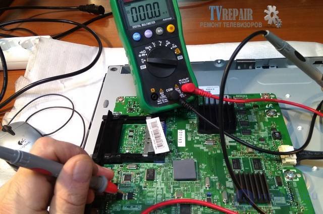
The system board in a TV performs a huge number of processes and can rightfully be called the main TV board, as well as the motherboard, the SSB unit, or the Main Board. It concentrates the control units for the entire TV device as a whole and for each of its parts individually. Repairing the system board at home is quite labor-intensive due to the complex diagnostics of this unit without appropriate measuring and service equipment. The only way out in this case is to use accumulated knowledge on typical defects from repair-related websites, including ours. In the "TV Faults" section, a lot of material of this kind has been published, and judging by the comments on it, this material has helped more than a few dozen people with DIY TV repair at home.
This is not the full range of responsibilities of the system board, but only a part of them. The development of TV technologies, the introduction of Smart TV, multimedia and other innovations keep adding new components and units to the SSB board. Below is a block diagram of the main board of a Philips TV on the TPM4.1E LA chassis, put into production a few years ago:
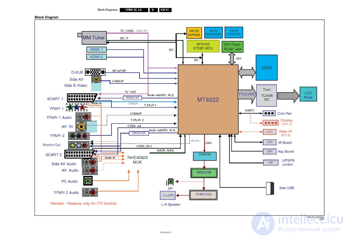
The core of the system board is the MT8222 central processor, which performs most of the functions assigned to this unit, together with the DDR, SPI Flash ROM, and NVRAM storage and data exchange devices. EDID memories are designed to match external devices using Plug and Play technology with the TV chassis, allowing it to recognize connected external equipment and adapt to it without user intervention, or with minimal intervention. The tuner and sound channel are mandatory for the main board, while the WT6703 STDBY MCU processor executes commands from the remote control and keypad. The video signal, converted by a certain algorithm, is fed over the LVDS bus to the matrix controller (Tcon), usually implemented as a separate unit, and then to the LCD panel.
 Information is transferred between the central processor and the other units of the system board over the bidirectional SDA and SCL communication lines. If a malfunction occurs in the operation of any unit, or no response about its normal state is received, the TV can be switched into an emergency mode. In this case, in Sony, Panasonic, and Philips equipment, an error indication mode is activated, which can be monitored by the flashes of LED indicators on the front panel of the device. The number of flashes and their frequency can explicitly or implicitly indicate the problematic area of the motherboard or another unit that is in a critical state. Information about the errors is available in the service manuals for the specific TV model.
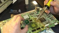 Returning to the block diagram, I'll draw attention to the Com Pair service port, intended for connecting the like-named device for diagnostics, log retrieval, and programming of Philips-brand TVs. Many modern TV receivers have a service interface for connecting diagnostic equipment produced by the manufacturer for warranty servicing of the equipment. As we understand, this instrument is not available to the average consumer. Therefore, relying on your own abilities, it should not be forgotten that diagnosing and repairing the system board of an LCD TV is the domain of professional repair technicians, who possess not only an understanding of the unit's operating logic and skills in restoring it, but also modern diagnostic equipment and tooling.
The most common defects of the TV's main board are the following:
If in the first case DIY SSB repair is still possible using original spare parts or universal converters, then resolving the firmware issue on your own without a programmer and software is not something everyone can manage.
No picture on the TV screen is one of the most common failures of this type of equipment regardless of model and brand.
There are quite a few probable causes for the picture disappearing from the screen. Very often the fault is triggered by lack of screen backlight.
Repairing a TV's backlight is an especially complex category of repair. Trusting it to a non-professional is extremely risky. Without the relevant knowledge, experience, and tools, it is impossible to do it yourself.
So if your TV turns on, responds to the remote, and has sound but no video, the best solution is to contact the VseRemont24 service center!
In good-quality TVs, the picture disappears after many years of flawless operation. Unfortunately, cases where brand-new equipment stops displaying an image happen just as often (if not more often).
 It may take less than a year(!) for your TV to break, if you were unlucky enough to buy low-quality equipment.
Most modern TVs with a liquid-crystal display use LED (light-emitting diode) backlighting. These are the models that dominate the Russian consumer electronics market.
An LCD TV screen is a liquid-crystal matrix, which is lit from behind by rows of soldered LED strips.
In other words, LED backlighting is a set of many small diode "bulbs" located in the TV behind the liquid-crystal matrix.
There are only two possible causes of TV backlight failure:
It is easy to confirm that a backlight fault is the cause of the missing picture. Shine a flashlight beam onto the screen of a running TV. With this forced illumination, you will be able to make out the image.
This is as far as self-diagnosis can go. After this, you need to call in a technician, who will diagnose the TV by disassembling it.
The technician removes the stand and the back cover of the TV, disconnecting the ribbon cable from the joystick. This gives access to three TV boards:
Removing the boards is a very painstaking task requiring maximum concentration. Any careless movement can result in the TV being permanently broken (for example, a torn ribbon cable). Even simply touching the matrix with dirty hands will later result in poor image quality.
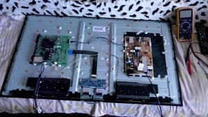 An experienced technician will carefully remove:
After these steps, nothing prevents proceeding to checking the backlight itself.
Sometimes a burned-out LED is visible to the naked eye — one or several bulbs are scorched at the mounting point, the color of their lenses changes, and they melt.
If there are no visible traces of burnt individual diodes, all the LED bulbs will have to be checked.
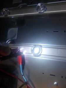
First, power is connected to each LED strip in turn. Whichever strip does not light up has the open circuit and/or short circuit.
Then power is applied one by one to each LED in the faulty strip. Whichever LED does not light up is the faulty one.
The lens is removed, and the faulty diode itself is desoldered (a hot-air soldering station is used for this). A new LED is then soldered in place of the faulty one. The lens is glued back in its original position.
The TV backlight repair is complete!
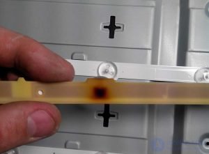 Afterward the technician checks that the backlight works (voltage is applied) and reassembles the TV in reverse order.
If the TV displays an image and there are no light or dark spots anywhere on the screen, the repair was successful!
If the diagnostics show that the LED strip is fine, the problem is hidden in the driver in the power supply.
Every LED driver is unique. After checking with a multimeter, a preliminary circuit analysis is required. Then, based on the data obtained, changes are made to the current in the LED strips, along with any repair or component replacement that is necessary.
Did you know that some TV dealers deliberately set the screen backlight level to maximum in all modes, in order to speed up LED failure and bring the moment of repair closer?
Maximum brightness contributes to premature failure of the LED backlight. That's why a repaired TV is set to a not-too-high (optimally 75%) brightness.
Typical problems
1) When it is not the backlight that is damaged but the matrix itself, its connecting ribbon cables, or the video processor, the image output may look as follows
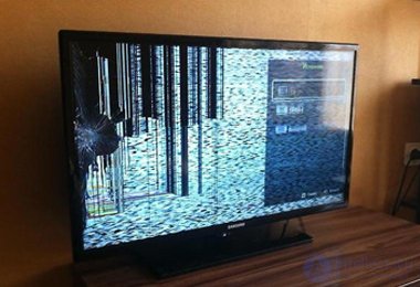
2) Dark spots on a white image
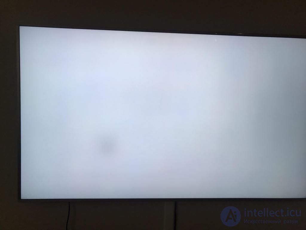 \
\
The spots do not disappear when switching channels. Even with the TV off, glare is visible in their place. Moreover, the darkened areas can be not only black or dark gray, but also white or colored. This indicates color-rendering errors or other faults.
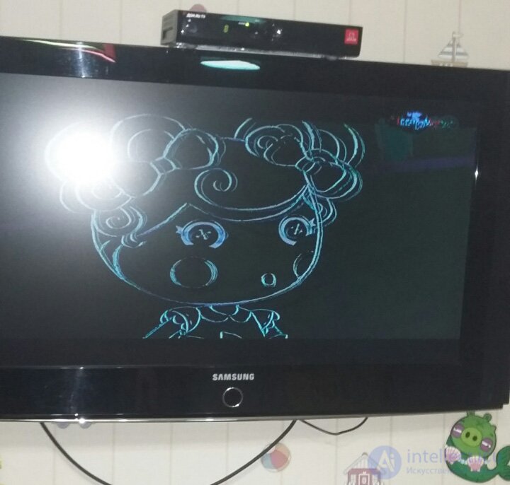
3) distorted image gamma
.
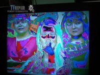
The fault in the Samsung LED TV shown in the photo looks quite distinctive: the TV image appears as a negative. There is a maximum color-gamut malfunction. During this Samsung TV repair, the technician's work was also related to the t-con board. In particular, a rather rare and fairly expensive gamma-corrector chip for this Samsung TV model was replaced, along with its firmware, which is necessary for correct operation after integration into the t-con board.
4 Matrix defect in a Samsung UE40h6410 TV.
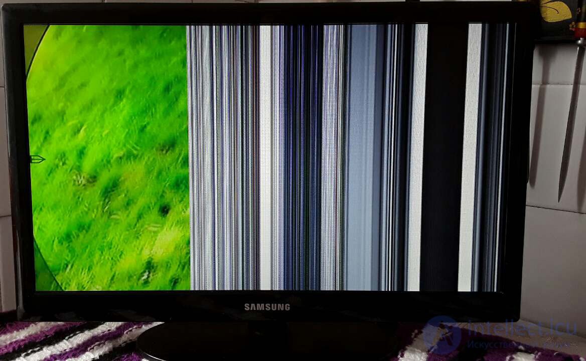
Matrix defects are fairly common in this series of Samsung TVs. This can show up as vertical stripes on the screen, or as a completely dark screen. In the second case there is no image, but there is sound and the TV channels can be switched. The symptoms of this TV fault are similar to those of a faulty matrix backlight. But in this case, when illuminated with a flashlight, no image can be made out.
5) A vertical stripe on the TV screen, 1 pixel thick.

This kind of image defect cannot be fixed, because the column decoder is damaged, which is an integral part of the LCD matrix and cannot be replaced. Most LCD TVs cannot have this kind of fault repaired. For example, it is not possible to restore the column decoder of a Chinese-made AU Optronics matrix. Sony LED TVs are fitted with such matrices. For example, repairing a Sony LCD TV, model kdl42w705b, with several colored vertical stripes on the screen that periodically appear and disappear, is not performed.
6) static darkening of part of the image
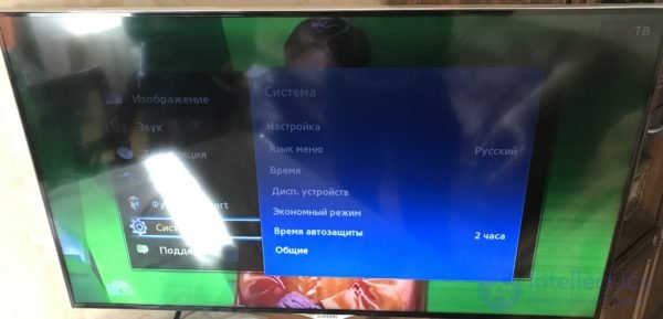
Darkening over part of the screen indicates that the TV's matrix backlight needs to be repaired
Modern LCD monitors, in principle, do not require systematic maintenance, due to their high level of technological sophistication.
But some maintenance operations can still be performed. These include operations such as:
Cleaning dust off the screen and casing with special wipes designed specifically for LCD monitors.
Cleaning dust off the monitor's internal electronic boards.
Some faults can be fixed yourself in a short time, while in other cases only replacement with a new unit will help. This article will cover the types of faults and how to repair a DVB-T2 digital set-top box for a TV yourself.
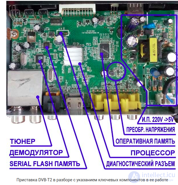
A disassembled DVB-T2 set-top box with its key operating components labeled
It should be noted right away that it is not always possible to fix a receiver. The main reason is that the device is already inexpensive (from 750 rubles) and, in the case of serious damage, it is more cost-effective to buy a replacement.
It is also not recommended to attempt repairing a digital receiver yourself if it is a complex universal set-top box. Such devices include several decoders, support different TV formats, and also have additional inputs and slots. When dealing with this kind of device, it is safer to take it to a service center for repair.
If the fault is minor and can be fixed without much effort and by hand, then you can open the casing and find the cause of the failure.
Before repairing it, you need to know what a DVB-T2 receiver consists of. It is in fact a complex device, including many components.
But in this case, only a few of them are of interest:
The other hardware or software components are not of interest for the reason that without professional skills it is impossible to fix their fault.
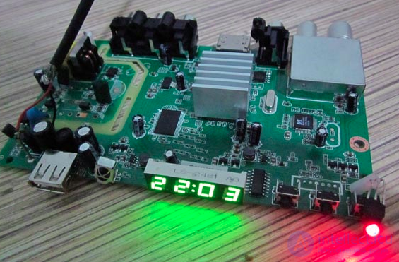
Working LED indicators on a digital receiver when power is applied clearly show correct current supply
The first thing to check is whether the current supply is working correctly. Depending on the result after powering on, you need to proceed differently:
First you need to check the indicator itself, for which it is enough to connect any small bulb (for example, from a flashlight) to the contacts with wires. If it lights up, the indicator is faulty; otherwise, you need to check the power supply.
If the above methods do not help solve the problem, an incorrect current supply can only be related to damage on the device board. In most cases this is destruction of contacts related to overheating or a short circuit. It is better to send an expensive DVB-T2 set-top box straight to a service center for repair, and replace a cheap receiver.
Important! If diagnostics show that the voltage converter is faulty, then only replacing it will help. Repair work in most cases does not lead to success.
Problems with it often lead to the complete stoppage of the DVB-T2 set-top box, and here there are several causes at once:
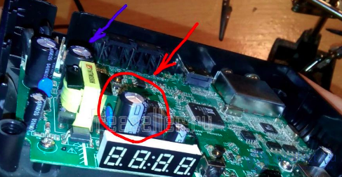
A swollen or damaged capacitor on the board always leads to a current supply that does not match the rated value for the DVB-T2 digital receiver
Attention! If only minor glitches in the interface or system options are observed, the first step is recommended to be an update, and only then should further steps be taken.
Minor glitches often occur because the device is running outdated software that is no longer supported by the developer.
A fault with the connectors often leads to poor picture quality or even a complete absence of image. In this case, no visible software glitches occur. Unlike most other set-top box components, connectors are easy to replace and solder in.
First, the RF IN input must be checked, since even the slightest disconnection from the board will primarily lead to strong noise. When using an old TV with a "wobbly" jack, strong interference could be observed.
Only with digital broadcast reception the situation is even worse, for two reasons:
With outputs it is simpler, and for operation it is enough to just have contact with the board. However, if a "wobbly" output is encountered, it is better to solder it more securely. Sooner or later such jacks come loose under the weight of the plug.
By standard, digital TV has a total of 3 RCA (tulip) audio-video outputs.
If there is a "silent movie" situation, the white or red output is faulty. When the opposite situation occurs and there is only sound, it is the yellow connector.
On the housing of an expensive receiver, instead of RCA there may be a Scart or HDMI connector. This is a single output, but with a larger number of contacts, which can only be resoldered with professional equipment.
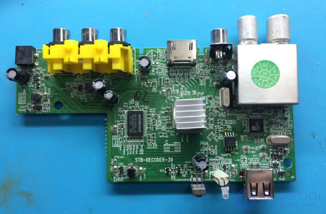
Decoder of a digital DVB-T2 set-top box, the antenna input and audio-video outputs are clearly visible on the board
If the digital TV set-top box is fully operational, but only the digital channels are not showing, the problem lies in the failure to recognize binary code. This is handled by the Digital DVB-T2 decoder, which may be faulty or not performing its function due to the absence of a command to do so.
To find the error in the software operation, you need to connect the decoder's contacts with wires to the UART diagnostic port. The device can be purchased at any radio market (100 - 200 rubles).
Its USB input needs to be plugged into a computer, and the HyperTerminal utility should be launched.
In the window that opens, enter the following settings:
After that, the DVB-T2 receiver is powered on and reading starts.
As a result, the following messages can be observed:
Attention! Reflashing the decoder has nothing to do with the software of the set-top box itself. The installer will have to be found separately, since it is included in the executable file for flashing the entire firmware. As an alternative option, you can reflash the entire DVB-T2 equipment.
Replacing the decoder is justified only for reasonably worthwhile DVB-T2 set-top boxes. Repairing a cheap model will cost more than buying a new receiver.
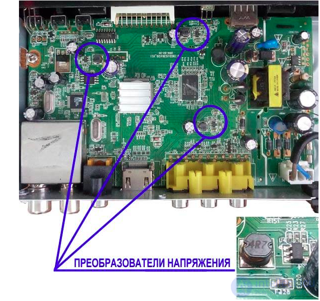
Digital DVB-T2 set-top boxes always have several voltage converters to supply different currents to the processor
If, after turning on the set-top box, a very weak startup sound can be heard which then abruptly stops, the processor is receiving a current different from what is required before repair. Here you need to check the voltage on the inductor or capacitor of each converter board. The rated value for a particular board should be 3.3, 1.8, 1.2 V respectively.
With correct voltage, you need to check the physical condition of the capacitor, since its swelling leads to an incorrect current supply. For the inductor, this problem is not relevant due to its durability, and in any other cases one can only speak of overheating or destruction of the board's contacts.
One voltage converter board can be replaced — replacement with labor will cost around 300 rubles. If 2 – 3 boards fail, then only replacing the DVB-T2 set-top box makes sense. Repairing the main device in this case is not practical.
As the only alternative, buying a faulty donor set-top box, in which all the boards are intact, can be used. In this case the model does not matter, the only thing that matters is the rated output current value.
To be fair, it should be noted that the reason for an incorrect current supply to the processor can also be the power supply. More precisely, the separator. If its board is faulty, and the receiver received a different voltage, but not a critical one, the main device will also continue to work.
But after conversion, the difference between the actual and rated current will be large. The first sign of a problem with voltage supply is general overheating of the set-top box. Repairing the power supply makes no sense, it is better to buy a new one.
For digital television, the key criterion is the quality of the received signal. The decoder can recognize information only when all the binary data arrives.
In addition, it should be taken into account that digital broadcasts use VHF waves, which attenuate faster.
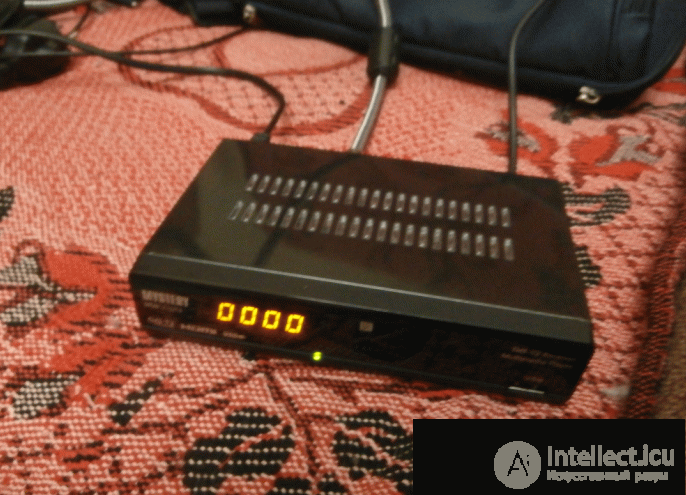
A cheap 20-channel DVB-T2 receiver works great as a donor when repairing an expensive device
From this it can be concluded that for digital reception, information must reach the decoder in full. Consequently, there should be no noise. And while only the antenna cable can carry it before the set-top box, on the next stretch of the path there are already more options.
Radiation dispersion in the receiver can be caused by:
If the problem with the plug or input is easily solved by replacement, a damaged conductor on the board is a complex problem. The whole point is that it not only transports the signal, but also prevents its dispersion.
Even a high-quality repair at home is unlikely to achieve high-quality transport of the television signal. The solution is to replace the conductor from a donor set-top box.
A TV Box is a special device that makes it possible to turn a regular TV into a Smart TV. At the same time, modern equipment periodically glitches, as a result of which the TV set-top box freezes. In most cases there is no serious problem here, so everything can be solved on your own.
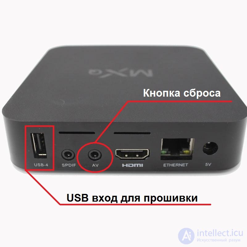
In addition, it sometimes happens that a smart TV box glitches as a result of hardware faults. The exact nature of the fault can only be determined after professional diagnostics. We do not recommend performing serious repairs yourself – in this case, there is always a risk of damaging the device. It is better to turn to trusted technicians for help, who can guarantee the quality of their work.
If there is a sign of no power, the main cause lies in damaged contacts. Small damage can be restored with liquid aluminum — a standard repair with a soldering iron. If the contact is completely burned out — only board replacement will help.
Important! Sudden voltage surges always lead to burnout of contacts on any board. If this is visually detected, the first thing to do is to check the power supply!
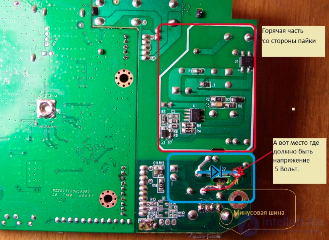
Contact damage — a common cause of failure of any electronic device
Mechanical damage (housing, control buttons) of cheap DVB-T2 boxes is best replaced using non-working analogs. In most cases, it is impossible to restore a specific element yourself.


Comments