
Lecture
Diagnosing and repairing a power bank is usually done following a specific sequence, because the device inside is fairly simple: batteries + control board + charging controller + 5V boost converter. Below is a practical diagnostic scheme used in repairs.
First, the condition of the device is checked without disassembly.
What to check:
1. External signs
case cracks
signs of drops
case bulging (a sign of swollen batteries)
2. Connectors
USB output
micro-USB / USB-C input
Look for:
connector play (looseness)
broken contacts
debris inside
3. Indication
do the LEDs light up
do they blink while charging
does it turn on when the button is pressed
Possible conclusions:
| Symptom | Possible cause |
|---|---|
| No indication | battery discharged / board not working |
| Blinks when connected | battery protection |
| Does not charge the phone | faulty boost converter |
Connect a charger.
Measure the current draw.
Normal:
0.5 – 2 A (depending on the model)
If:
0 A
connector is broken (open circuit)
board has burned out
0.01–0.1 A
battery protection triggered
dead battery
pulsates
bad battery
After opening, check:
1. Batteries
swelling
damage
signs of overheating
2. Board
burned components
torn traces
poor soldering
Most power banks use Li-ion or Li-Po cells rated at 3.7 V.
Measure the voltage of each cell.
Normal values:
| Voltage | Condition |
|---|---|
| 4.2 V | fully charged |
| 3.7 V | normal level |
| 3.0 V | nearly discharged |
| <2.5 V | deep discharge |
If the battery is:
0 V → protection triggered or open circuit
<2 V → often already damaged
The battery usually has a protection board.
Check:
whether there is voltage at the board input
whether there is voltage at the board output
If:
the battery has 3.7 V, but the output is 0 V
→ the protection has disconnected the battery.
Causes:
short circuit
overload
deep discharge
Sometimes a brief direct recharge helps.
The board converts 3.7 V → 5 V USB.
Measure the voltage at the USB output.
Normal:
5.0 – 5.2 V
If:
| Symptom | Cause |
|---|---|
| 0 V | converter does not start up |
| 3–4 V | bad battery |
| fluctuates | overload |
Connect:
USB tester
a load of 1–2 A
Observe:
voltage
current
heating
If the voltage drops below 4.7 V, this means:
battery is worn out
bad converter
The most common problem.
Repair:
resolder
replace the connector
Signs:
case is bulging
low capacity
discharges quickly
Repair:
battery replacement
Signs:
does not charge
does not output 5 V
Repair:
board replacement
it's easier to install a new powerbank module
If using 18650 cells.
Sometimes:
contact is oxidized
the nickel strip has come off
Device structure:
USB input (charging)
│
charging controller
│
Li-ion battery
│
BMS protection
│
boost DC-DC
│
USB output 5V
Needed for repair:
multimeter
soldering iron
USB tester
lab power supply (preferable)
USB load
Tip:
In most cases, repairing a power bank comes down to three things:
battery replacement
resoldering the connector
controller board replacement
Below is an architectural block diagram of a power bank, made in datasheet style (functional block diagram). Such diagrams show not the repair process, but how the device is structured internally.
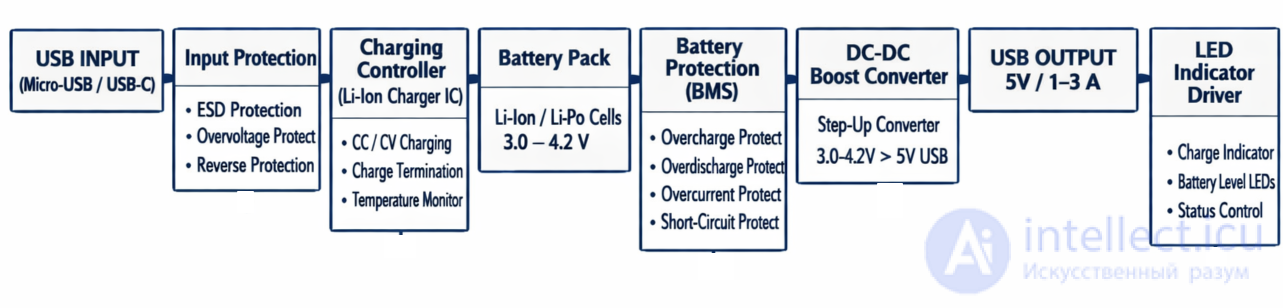
Protects the device from:
static (ESD)
reverse polarity
excessively high voltage
Lithium battery charging controller.
Modes:
Pre-charge — if the battery is heavily discharged
CC (constant current) — main charge
CV (constant voltage) — topping off to 4.2V
Termination — end of charge
Usually:
1× Li-Po
or
1–4 × 18650
Voltage:
3.0 V — discharged
3.7 V — nominal
4.2 V — full charge
Disconnects the battery if:
overcharge
deep discharge
short circuit
excessive current
Boost converter:
3.0–4.2 V → 5 V
Uses:
an inductor
MOSFET
PWM controller
Determines:
whether a device is connected
whether the output needs to be enabled
Many power banks shut off if the current is < 50-100 mA.
Shows:
battery level
charging
output operation
Interesting fact:
In modern power banks, all these blocks are often located inside a single chip.
For example:
IP5306
IP5328
AXP192
ETA9740
Below are 10 typical functional diagrams of power banks that are most commonly found in real devices. They differ in the level of integration: from simple modules to modern single-chip solutions.

Features:
a single 18650 cell
cheap power banks
often used in DIY
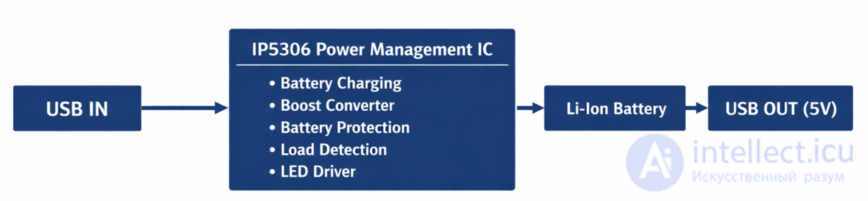
Features:
everything in a single chip
90% of Chinese power banks
supports auto shutoff
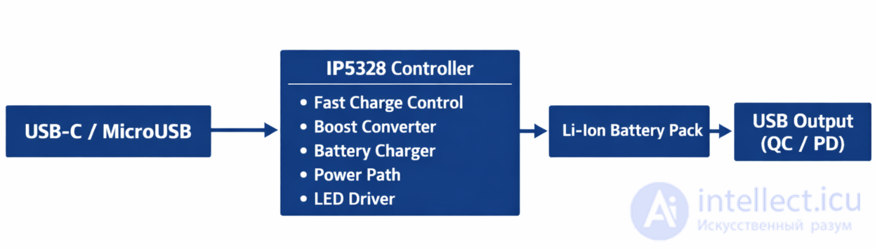
Features:
QuickCharge support
modern models

Features:
high power
often found in DIY projects

Features:
improved Li-Ion charging
sometimes used with solar panels

Features:
large capacity
standard circuit

Features:
used in large powerbanks
more complex BMS
Solar Panel
│
▼
Solar Charger IC
│
▼
Li-Ion Battery
│
▼
Boost Converter
│
▼
USB OUT
Features:
slow charging
popular in outdoor/hiking powerbanks
USB IN
│
▼
Power Path Controller
│
├─ Device powered directly
└─ Battery charging
│
▼
Battery
│
▼
Boost Converter
│
▼
USB OUT
Features:
the device can be powered and charge at the same time
USB-C PD Controller
│
▼
Power Management IC
│
├── Battery Charger
├── PD Negotiation
├── Boost / Buck Converter
└── Protection System
│
▼
Li-Ion Battery Pack
│
▼
USB-C Output
(5V / 9V / 12V / 20V)
Features:
Power Delivery
bidirectional USB-C
Which functional circuits are most common
Real repair statistics:
| Circuit | Frequency |
|---|---|
| IP5306 | ~50% |
| TP4056 + Boost | ~25% |
| IP5328 | ~10% |
| USB-C PD controller | ~10% |
| others | ~5% |
💡 Useful fact for repair:
If you open 10 random powerbanks, roughly 5 of them will have an IP5306 chip.
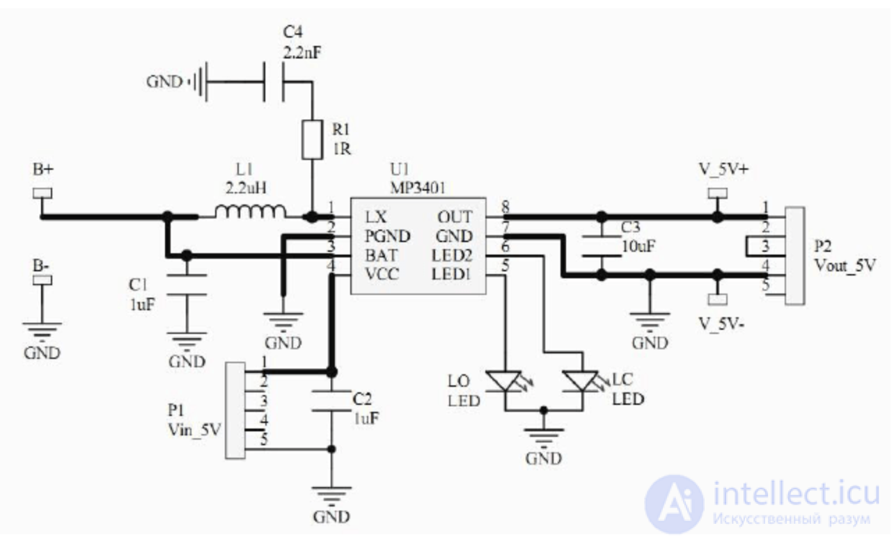
Powerbank controller circuit based on the MP3401 chip.
For repair, it is highly desirable to find the controller circuit. As a rule, it is a chip in a standard configuration. The chip type can be found on its case.
Below is a powerbank fault service chart — a table typically used during repair. It links symptom → possible cause → what to check → repair type.
| Symptom | Possible cause | What to check | Repair type |
|---|---|---|---|
| Powerbank does not turn on at all | deep battery discharge | battery voltage | pre-charging or battery replacement |
| faulty power controller | presence of power on the board | board replacement | |
| poor battery contact | battery soldering | resolder the contacts | |
| Indicators do not light up | no power | voltage on the battery | restore power |
| faulty LED driver | LED control signal | board replacement | |
| Powerbank does not charge | broken input USB | mechanical condition of the connector | connector replacement |
| faulty charge controller | charging current | chip replacement | |
| bad cable or power supply | input voltage | replace the cable | |
| Charging is very slow | bad cable | voltage drop | replace the cable |
| weak power supply | measure input current | use a more powerful adapter | |
| battery degradation | capacity test | battery replacement | |
| Powerbank discharges quickly | battery lost capacity | load test | battery replacement |
| high leakage on the board | quiescent current | board replacement | |
| faulty DC-DC converter | converter efficiency | controller replacement | |
| Does not charge the phone | no 5V at the output | USB voltage | DC-DC repair |
| battery protection disabled | BMS output | protection reset | |
| faulty boost converter | voltage after the inductor | chip replacement | |
| Output voltage below 5V | weak battery | battery voltage | battery replacement |
| overload | load current | reduce the load | |
| faulty DC-DC | voltage on the inductor | controller replacement | |
| Powerbank turns off after a few seconds | low load current | consumption current | normal behavior |
| bad battery | voltage sag | battery replacement | |
| overcurrent protection | check for short circuit | eliminate short circuit | |
| Gets very hot | short circuit | line resistance | eliminate short circuit |
| faulty converter | consumption current | board replacement | |
| damaged battery | battery temperature | battery replacement | |
| Case swelling | battery swollen | visual inspection | urgent replacement |
| Powerbank only charges sometimes | bad USB contact | connector | resolder |
| cracked trace | board inspection | restore the trace | |
| Indicator shows full charge, but battery is empty | faulty fuel gauge | level signal | controller replacement |
| Very small capacity | worn cells | capacity test | battery replacement |
Practice shows that 80% of powerbank failures — are just 4 causes:
Usually a technician takes just 4 measurements:
1. Battery voltage
2. Whether there is charging current
3. Whether there is 5V on the USB
4. Behavior under load
Based on these four parameters, the problem can almost always be identified.
Below is a typical powerbank diagnostics and repair flowchart — a sequence of checks from simple to complex.
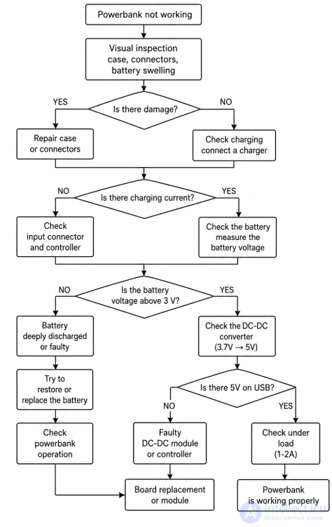
Diagnostics always follows this order:
External inspection
Checking charging
Checking the battery
Checking the protection board
Checking the step-up converter
Load test
This allows the problem to be quickly found in 80% of cases.
Below is a more professional powerbank diagnostic flowchart, formatted as is typically done in a service manual / troubleshooting guide. Such diagrams use standard elements: start, checks, decisions, and repair actions.
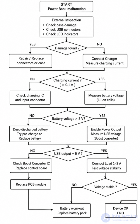
How to read this diagram (as in service manuals)
Typical logic:
START — the device does not work
Visual inspection — rule out mechanical problems
Charging test — check the input circuit
Battery test — battery condition
Boost converter test — check the 5 V converter
Load test — check under real load
A feature of service diagrams:
they are built to minimize disassembly — first external causes are checked, then power, and only at the end the electronic board.
The method is called a quick internal resistance test + voltage sag test. But an important point right away: you cannot measure the exact capacity in 5 minutes, you can only quickly assess the battery condition (alive / dead / normal).
USB tester (preferably)
USB load 1–2 A
or a phone + USB tester
PowerBank → USB tester → USB load (2A)
Immediately check the voltage.
Normal values:
| Voltage | Condition |
|---|---|
| 5.0–5.2 V | excellent battery |
| 4.8–5.0 V | normal |
| 4.6–4.8 V | worn |
| <4.6 V | battery almost dead |
After 5 minutes check how many mAh the USB tester showed.
For example:
2A × 5 minutes
5 minutes = 1/12 hour
2000 mA × 1/12 = 166 mAh
Now multiply by 12.
Example:
USB tester showed 150 mAh
150 × 12 = 1800 mAh (approximate capacity)
This is a quick estimate.
The powerbank converts:
3.7V → 5V
Therefore the real capacity will be:
reading × 1.3 – 1.5
Example:
1800 mAh × 1.4 ≈ 2500 mAh battery
Signs:
| Symptom | Cause |
|---|---|
| voltage drops below 4.5 V | high internal resistance |
| powerbank shuts off | battery has degraded |
| gets hot | cell is damaged |
This is a very common powerbank problem.
The controller disconnects the battery if:
Vbattery < 2.5V
You need a lab power supply.
Voltage: 4.2V
Current: 50–100 mA
Connect directly to the battery.
Wait until the voltage rises to:
2.8 – 3.0 V
After that:
connect a regular charger
the controller starts working again
If there is no lab power supply.
Take:
a 5V charger
a 100–200 Ω resistor
Circuit:
5V
│
resistor
│
+ battery
Hold for 10–30 seconds.
The battery will rise to ~3V.
Sometimes it's done like this:
good Li-ion
│
├──── + to + of discharged
│
└──── - to -
Through a 10–20Ω resistor.
For 10–20 seconds.
If there is:
| Sign | What to do |
|---|---|
| voltage < 1.5V | discard |
| battery has swollen | discard |
| gets very hot | discard |
| does not hold a charge | replace |
Never apply directly to a Li-Ion cell:
5V without current limiting
This can lead to:
overheating
swelling
fire
In powerbank repair:
about 40% of faults are simply a deeply discharged battery.
Sometimes it is enough to raise it to 3V, and the device works again.
Parts for repairing powerbanks can be bought in three main places: local electronics stores, national marketplaces and international platforms. Below is where it is actually more convenient and cheaper.
Almost all repair modules are sold there.
What you can buy:
powerbank boards
charging controllers
USB connectors
cases
ready-made modules
For example, a module based on IP5306 can be bought for about 1-2 dollars.
Also sold:
TP4056 charging boards
BMS boards
modules with QuickCharge
Example of an online store:
Electrochip
There you can buy:
TP4056 modules
USB connectors
powerbank cases
charging controllers
For example, a TP4056 charging module costs ~0.5 dollars
If you repair often — this is the best source.
You can buy:
powerbank boards
controllers
indicators
cases
boost converters
Pros:
very cheap
huge selection
Cons:
delivery 2–4 weeks
Best of all:
batteries from disassembled laptops
old powerbanks
batteries from electric scooters
It is only worth buying new 18650 cells from trusted sellers, because there are many counterfeits.
If you repair regularly, it is worth keeping a stock:
| Part | What for |
|---|---|
| TP4056 | battery charging |
| IP5306 | full powerbank controller |
| MT3608 | boost converter |
| BMS 1S | battery protection |
| USB connectors | frequent failure |
| 18650 batteries | battery replacement |
For example:
IP5306 powerbank board
≈ 2–3 dollars
Sometimes it's cheaper to replace the board entirely than to look for the faulty component.
Technicians' tip:
Often the cheapest source of spare parts is broken powerbanks.
From a single one you can salvage:
batteries
the board
connectors
the enclosure

Comments