
Lecture
Nowadays, uninterruptible power supplies are a complex system with microprocessor control, whose main task is to protect connected equipment from harmful effects that lead to data loss and damage to devices, as well as to ensure autonomous operation of computer systems during power supply disturbances.
There are three main types of modern uninterruptible power supplies (UPS). Let's consider the pros and cons of each, as well as the basic circuit diagrams of their design.
There are three main types of modern uninterruptible power supplies (UPS). Let's consider the pros and cons of each, as well as the basic circuit diagrams of their design.
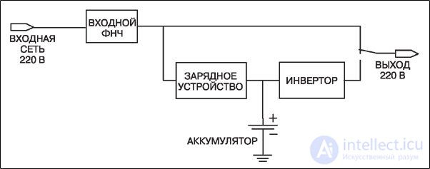
Offline UPS (off-line, Standby, back ups, or reserve) – is a type of uninterruptible power supply whose operating principle consists in switching the equipment to a backup battery (which is a component of the UPS) when power failures occur.
| PROS: | CONS: |
| simplicity cost-effectiveness compactness |
lack of input voltage stabilization when operating from the mains higher battery wear (compared to other types) |
APPLICATION:
for short-term protection of home PCs, office computer equipment.
UPS circuit diagram with offline technology
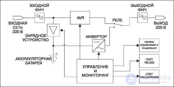
Line-interactive – is a type of UPS that is capable of regulating the output voltage when the input voltage decreases or increases over a wide range – without switching to battery operation. UPS units of this type are divided into devices with approximated sine wave and fully sinusoidal output voltage.
| PROS: | CONS: |
| compactness cost-effectiveness input voltage stabilization low cost |
lack of output voltage waveform correction when operating from the mains stepped output voltage change presence of switching time to battery power |
APPLICATION:
for protection of groups of computers, network and other critical computing and telecommunications equipment.
Line-interactive UPS circuit diagram
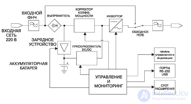
Double conversion (online) – is a type of UPS in which electrical energy is converted twice – low-quality input voltage into a DC voltage on the internal bus, from which an output voltage with reference characteristics is formed. The switching time to battery operation in an online UPS is zero.
| PROS: | CONS: |
| constant voltage and frequency stabilization complete filtering of surges and high-frequency interference from the main power grid no influence of connected equipment on the main power grid instantaneous switching to batteries in case of failures |
complexity of design and higher cost additional power consumption in double-conversion mode |
APPLICATION: File servers, workstations, data centers, and other critical computing and telecommunications equipment that place increased demands on power quality.
UPS circuit diagram with online technology
Suppose you decided to buy an uninterruptible power supply (UPS) specifically so that, should anything happen, your valuable home electrical appliances would not suffer from abnormal shutdowns and would not burn out from voltage surges. A reasonable goal, but … suddenly it turns out that the UPS is faulty. Either it constantly beeps about operating in emergency mode, even though the mains voltage is completely normal, or it doesn't turn on at all… What to do? Take it to a service center for repair? Don't rush…
First, it makes sense to inspect it carefully and check — can the device be repaired on your own? On the one hand, a UPS is a fairly complex device, but on the other hand — even in complex devices, a large percentage of faults consist of trivial contact issues.
By the way — it is precisely these that are most often the cause of a situation where the UPS doesn't turn on at all. Very often, to "fix the fault" it is enough to check the fuse (circuit breaker) or "ring out" the cord with the plug leading to the outlet.
Before opening the power supply, you can try turning on the UPS to be sure of the diagnosis. A correctly made diagnosis is half the cure.
But it may happen that the UPS for some reason keeps switching to emergency mode (signaling this with a desperate beeping), even though nothing serious is happening in the mains.
Why does it do this? To understand this, you first need to look at the UPS circuit diagram and estimate what could break in it.
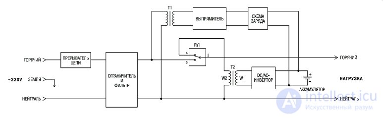
The most common UPS design is a combination of a voltage stabilizer and a mains filter with a branch of part of the voltage to a rectifier, battery, and DC-to-AC converter. Under normal conditions, electricity from the stabilizer is supplied directly to the load (in which case contacts 5 and 3 on relay RY1 will be connected), and if the mains voltage disappears, the relay connects contacts 4 and 3 — and the voltage inverter (converter) starts operating from the battery, which should ideally be enough for 15-20 minutes of operation of the previous load.
So — if the wrong relay is installed (or simply misadjusted), it may trigger not on a complete loss of mains voltage, but simply on its reduction, which is possible if the UPS has a relay-type stabilizer installed.
To fix such a fault, it will be enough to turn the relay adjuster a quarter turn in the direction of reduced sensitivity.
The next possible source of UPS malfunction is the battery. It may lose capacity due to improper use, or it may dry out or "break down" — in which case the UPS either will not operate for the intended time, or the controller will start giving a UPS fault signal.
What to do in this case?
First of all — don't panic. If the UPS has just been purchased, it is quite possible that the battery in it is not yet charged. In that case, on first power-on the controller will "detect a fault," but after a few minutes it will settle down, since the battery will start charging.
Nevertheless, after such a signal it is still better to additionally check the battery capacity. This is quite simple to do — leave the UPS switched on without a load for a day so the battery fully charges, then connect a precisely known load (for example — a 100-watt light bulb) and disconnect the UPS from the mains.
In this case, it should start operating in emergency mode — and in this mode the bulb should light normally for about 20 minutes. There is no need to torture the UPS further — too deep a discharge is also dangerous for the battery. If the battery in the UPS cannot withstand the required 20 minutes — then nothing can be done about it: you will have to deal with each battery individually. Perhaps they can be "cured"…
And finally, there is one more piece of advice… conditionally useful (so to speak).
If, in your search for the fault, you removed the cover from the device, take a look at the board on which all the "electronic guts" of the UPS are concentrated.
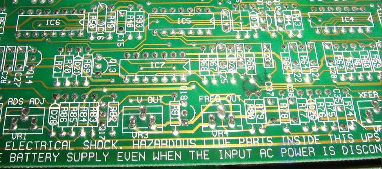
In some devices (especially — those made in China), the ribbon wires may peel away from the plastic base and tear. If you discover such a mishap, you can fix it yourself with a soldering iron.
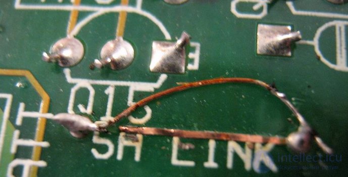
We warn you right away: this method of fault repair is called "throwing a booger" in electricians' slang, and it will deprive you of your right to warranty service. So it's better not to resort to it prematurely…
Uninterruptible power supplies, like any other equipment, need timely maintenance, the absence of which can lead to the UPS failing to start. This is possible for a wide variety of reasons. There is a set of typical faults that can cause the UPS not to turn on, however, it is worth remembering that each UPS device may have its own peculiarities, which can introduce adjustments to the process of diagnosing and repairing the UPS.
Since the UPS is the most important part of the power system, its failure exposes the equipment to a certain risk. The simplest way to eliminate a fault is to study the instructions. There is a good chance that you will find there a description of the problems that may arise during operation of the specific uninterruptible power supply model. Most manuals contain at least a little information on how to fix a minor fault.
To avoid problems, it is advisable to use the software that comes paired with the UPS. With its help, you can monitor the state of the system and take the necessary measures in a timely manner.
How to check the UPS for functionality? To do this, you need to turn off the electricity and track the load operating time. If the operating time is short, then most likely the fault is caused by high battery wear. In this case, repairing the computer UPS will consist of a trivial battery replacement. It is important to remember that old batteries cannot be thrown away due to their high environmental impact — batteries that have outlived their usefulness must be handed in for recycling.
If the UPS beeps at startup, this may be a signal that an overload has occurred. It may also signal that the battery has failed the test provided for by the system. The cause of the unpleasant beeping can be understood using the indicators on the front panel or using the software.

Eaton 9PX UPS control panel
Why doesn't the UPS work on battery? Such a problem can be caused by a faulty charger, as a result of which the battery is unable to provide the declared autonomous operation time. You can check the charge by measuring the voltage at the terminals without disconnecting from the mains. It should be 13-14 V for a UPS with one battery and 26-28 V for series-connected batteries.
If the UPS for the computer is not working, you should first check the condition of the battery. In general, its service life is a maximum of 4-5 years. If your UPS is more than 5 years old, the problem is most likely the battery. The condition of the battery can be determined by the voltage level. If it is above 12.4 V, everything is fine, but if it is less than 12 V, it is time to say goodbye to it.
You can also test the battery using an ordinary 100 W light bulb. To do this, connect the light bulb to the battery and see how long the battery charge lasts. Typical batteries used in uninterruptible power supplies are lead-acid with a capacity of 7 Ah. A new battery of this type provides about 20 minutes of operation for a 100 W light bulb. As a result, if the battery shows a time that is less than 70% of normal, it needs to be replaced.
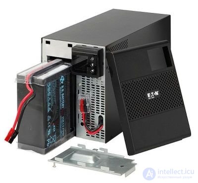
If the battery is functioning properly, the causes of the malfunction may lie in incorrect battery connection. The cause may also be improper operation of the UPS program, which indicates that the device needs calibration. Otherwise, the causes may lie in a fault in the UPS components, which cannot be identified independently.
It is not uncommon for the UPS to simply not turn on. What should be done in this case? In low-power uninterruptible power supplies, the control board is usually powered from the battery, which is why the UPS does not turn on due to low charge. In this situation, you need to try charging the battery. Some devices can charge under these conditions, so it is enough to simply plug the UPS outlet into the mains and wait some time. You can also remove the battery and charge it with a suitable charger.
If you have just purchased the device but it does not turn on, you need to check whether the battery is connected. According to transportation rules, such devices must be transported with the battery disconnected. Another reason the UPS does not start may be a stuck power button. There may also be cable breaks caused by a short circuit.
Another reason the UPS is not working may be overload. This is quite simple to check — you need to disconnect the entire load. If the UPS then works, you need to identify the equipment causing the overload. This can be done by sequentially connecting loads to the UPS. Afterward, that load should be excluded. If the UPS does not turn on even without a load, the device should be taken for diagnostics to a service center. Replacing the battery yourself may not solve the problem, so there is no point in simply buying a second battery.
Servicing powerful UPS units can be dangerous. This is due to the presence of large currents and voltages, which, in the event of a short circuit, can damage the equipment and cause burns. For this reason, all precautions should be observed, and it is even better to contact a specialized center.
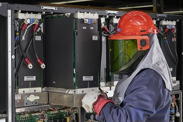
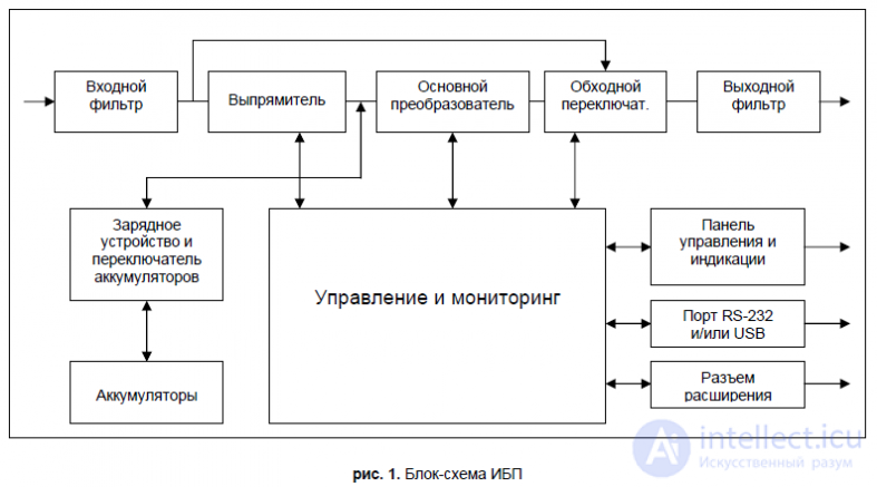
When repairing a UPS, the following methods should be used:
A. Assembly analysis method. This method allows, using the human senses (sight, hearing, touch, smell), to find the location of a defect with the following signs:
B. Measurement method. Based on the use of measuring instruments when searching for defects: a voltmeter, an ohmmeter, an oscilloscope.
When protection trips periodically, for example, it is preferable to start by analyzing the voltages on the transistor leads measured with a high-resistance voltmeter. This is because when checking a faulty transistor with an ohmmeter, a periodic break in its lead may be temporarily eliminated, but such a restoration of the circuit's functionality is unreliable, and the "lost" defect will inevitably reappear later.
C. Substitution method. Based on replacing a suspect component with a known good one.
D. Elimination method. Based on temporarily disconnecting (in case of possible leakage or breakdown) or bridging leads (in case of possible break) of suspect elements.
Group stabilization of UPS output voltages is characterized by the fact that as the load current of one of the secondary rectifiers increases, the load on the switching transformer increases, and this affects the output voltage values of all rectifiers connected to it. Therefore, when searching for a defect, both "continuity testing" of load circuits and disconnection of suspect circuits should be widely used.
E. Stimulus-response method. Based on analyzing the circuit's response to various manipulations performed by the technician:
F. Burn-in method. Allows finding intermittently recurring defects and checking the quality of the repair performed (in the latter case, the burn-in should last at least 4 hours).
G. Tapping method. Allows identifying assembly defects on a powered-on UPS by rocking components, tugging on conductors, tapping the chassis with a rubber mallet, etc.
H. Equivalents method. Based on temporarily disconnecting part of the circuit and replacing it with a combination of elements that have the same effect on it. Such sections of the circuit may include pulse generators, auxiliary DC voltage sources, and load equivalents.
In this case, any specific characteristics of the unit obtained from its documentation, or read off its housing, can and should be used when repairing it.
When troubleshooting a fault, the technician should not only apply these methods in their pure form, but also combine them.
Typical causes of emergency conditions in a UPS circuit include: mains voltage "surges," causing an increase in the pulse amplitude at the collector of the switching transistor; a short circuit in the load circuit; an avalanche-like rise in collector current due to saturation of the switching transformer's core, for example, due to a change in the magnetization characteristic of the core during overheating or an accidental increase in the duration of the pulse that turns on the transistor.
One of the most typical faults is the "breakdown" of the rectifier bridge diodes or the powerful switching transistors, leading to a short circuit in the UPS's primary circuit. Breakdown of the rectifier bridge diodes can lead to a situation where the mains AC voltage is applied directly to the electrolytic smoothing capacitors of the mains filter. In this case, the electrolytic capacitors at the output of the rectifier bridge explode.
A short circuit in the UPS primary circuit can occur, mainly, for two reasons:
As a result, impulse noise with an amplitude of up to 1 kV may occur in the mains, which usually leads to "breakdown" across the collector-emitter junction of the powerful switching transistors.
The third cause of a short circuit in the UPS primary circuit is the incompetence of repair personnel who take measurements with a grounded oscilloscope in the UPS primary circuit!
In the event of a short circuit in the UPS primary circuit, the current-limiting thermistor with a negative temperature coefficient burns out (with an explosion). This happens after replacing the blown fuse and reconnecting to the mains, if the underlying cause of the short circuit has not been eliminated. Since these resistors can sometimes be hard to obtain, technicians repairing UPS units sometimes simply install a short-circuiting jumper in the place where the thermistor should be.
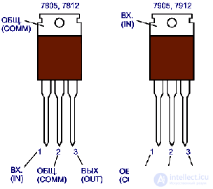
Fig. 11. Pinout of three-terminal integrated regulators in a TO-220 type package.
Please also note that when replacing powerful switching transistors, it is best to use transistors of the same type and from the same manufacturer. Otherwise, installing a different type of transistor can lead either to their failure or to the UPS startup circuit not functioning (in the case of using transistors more powerful than those originally in the circuit).
The second typical UPS fault is failure of the TL494 control chip.
The chip's functionality can be verified by evaluating the operation of its individual functional blocks (without desoldering it from the UPS circuit). The following procedure can be recommended for this:
Operation 1. Checking the functionality of oscillator DA6 and reference source DA5.
Without plugging the UPS into the mains, apply a supply voltage of 10-15V from a separate source to pin 12 of the control chip.
The functionality of oscillator DA6 is assessed by the presence of a sawtooth voltage with an amplitude of 3.2V at pin 5 of the chip (provided the frequency-setting capacitor and resistor connected to pins 5 and 6 of the chip, respectively, are functioning correctly).
The functionality of reference source DA5 is assessed by the presence of a constant voltage of +5V at pin 14 of the chip, which should not change when the supply voltage at pin 12 changes from +7V to +40V.
Operation 2. Checking the functionality of the digital path.
Without plugging the UPS into the mains, apply a supply voltage of 10-15V from a separate source to pin 12 of the control chip.
The functionality of the digital path is assessed by the presence of rectangular pulse sequences at pins 8 and 11 of the chip (if the chip's output transistors are connected in a common-emitter configuration) or at pins 9 and 10 (if they are connected in a common-collector configuration) at the moment power is applied.
Check for a phase shift between the sequences of output pulses, which should be half a period.
Break the printed trace (after first removing power from pin 12 of the chip) that shorts pins 14 and 13 of the chip, and connect pin 13 to pin 7 ("ground"). Verify the absence of a phase shift between the sequences of output pulses at pins 8 and 11 (or 9 and 10).
Operation 3. Checking the functionality of the "dead zone" comparator DA1.
Without connecting the UPS to the mains, apply a supply voltage of 10-15V from a separate source to pin 12 of the control chip.
Make sure the output pulses at pins 8 and 11 disappear when pin 14 of the chip is shorted to pin 4.
Operation 4. Checking the functionality of the DA2 PWM comparator.
Without connecting the UPS to the mains, apply a supply voltage of 10-15V from a separate source to pin 12 of the control chip.
Make sure the output pulses at pins 8 and 11 disappear when pin 14 of the chip is shorted to pin 3.
Operation 5. Checking the functionality of the DA3 error amplifier.
Without connecting the UPS to the mains, apply a supply voltage of 10-15V from a separate source to pin 12 of the control chip.
Check the voltage level at pin 2, which should differ from zero. By varying the voltage at pin 1, supplied from a separate power source, within the range of 0.3V to 6V, monitor the change in voltage at pin 3 of the chip.
Operation 6. Checking the DA4 error amplifier. Without connecting the UPS to the mains, apply a supply voltage of 10-15V from a separate source to pin 12 of the control chip.
Check the voltage level at pin 3, having first set amplifier
DA3 to the "hard 0" state at the output. To do this, the voltage at pin 2 must exceed the voltage at pin 1. Check for the appearance of voltage at pin 3 when the potential applied to pin 16 exceeds the potential applied to pin 15.
The third characteristic fault is the failure of the rectifier diodes in the UPS secondary circuits (as a rule, this is a breakdown or a decrease in the diode's reverse resistance).
You must make the correct choice of replacement diode based on current, cutoff switching frequency, and reverse voltage!
Do not forget that Schottky diodes are used in the +5V generation channel, while ordinary silicon diodes are used in the other channels!
We remind you of the need to ensure good heat dissipation for the rectifier diodes in the +5V and +12V generation channels!
When checking rectifier diodes, it is advisable to unsolder them from the circuit, since, as a rule, numerous elements are connected in parallel with them, and checking the diodes without unsolderding them from the circuit becomes incorrect in this case.
We draw your attention to the fact that the UPS may generate all output voltages while the PG signal is 0V, and the processor will be blocked.
Do not forget that quite a lot of elements are involved in the PG signal generation circuit, which can also fail.
The faults listed are the main ones and, as a rule, not difficult to find.
Keep in mind: sometimes malfunctions occurring in the UPS circuit during measurements lead to emergency operating modes of the power transistors. Malfunctions can be caused by an increase in the stray capacitance of the UPS circuit elements at the point where the instrument's measuring probes are connected!
The mains fuse (3-5A) is always located on the UPS circuit board and practically protects the mains from short circuits in the UPS, rather than protecting the UPS from overloads.
Almost always, the burnout of the mains fuse signals that the UPS has failed.
A distinctive indicator of a working UPS can be the rotation of the fan, which is started by the +12V (or -12V) output voltage. However, to bring the UPS into its rated mode and correctly monitor all UPS output voltages, an external load is required, either on the system board or on resistors that provide the full range of current loads specified in Table 2. To assess the UPS's operability as a first approximation, a load resistor with a rating of about 0.5 Ohm and a dissipated power of at least 50W can be used on the +5V generation channel.
A functional UPS should operate silently. This follows from the fact that the conversion frequency is beyond the upper threshold of the audible range. The only source of acoustic noise is the running fan.
If, in addition to the fan's hum, you hear squealing, "ticking," or other sounds, this unambiguously indicates a UPS fault or that it is in an emergency mode! In this case, you should immediately disconnect the UPS from the mains and eliminate the fault.
For more complex cases of UPS failure, it is necessary to have a good understanding of the principles of UPS operation, the cause-and-effect relationship between individual circuit units, and, of course, to have the schematic diagram of the given power supply unit.
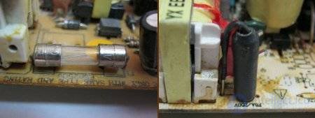
If you find that the fuse has blown, do not rush to replace it and turn on the PSU. In 90% of cases, a blown fuse is not the cause of the fault, but its consequence. In this case, you should first check the high-voltage part of the PSU, namely the diode bridge, the power transistors, and their surrounding circuitry.
Fixed resistors used in UPS circuits can be grouped into two main classes: wire-wound and composition.
The equivalent circuit of a resistor depends on the type of resistor and its manufacturing process.
However, for most cases, the circuit shown in fig. 12, c is suitable.
In a typical composition resistor, the shunt capacitance shown here has a value of about 0.1-0.5pF.
The inductance value is determined mainly by the leads, with the exception of wire-wound resistors, in which the resistor itself makes the main contribution to the inductance.
With the exception of wire-wound resistors or other types of resistors with very low resistance, the resistor's inductance can usually be neglected when analyzing a circuit.
However, the resistor's inductance makes it sensitive to interference from external magnetic fields. Shunt capacitance is significant only for high-resistance resistors.
Foreign manufacturers usually use a coded designation of resistor parameters in the form of a set of colored rings on their bodies.
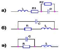
Fig. 12. Equivalent circuits of radio components: a) - capacitor; b) - inductor coil; c) - resistor.
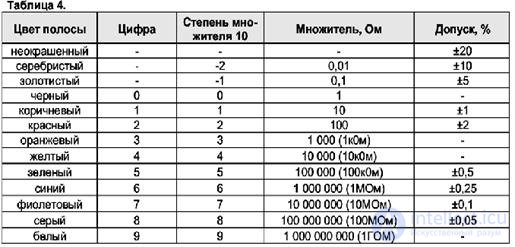
Each color corresponds to its own digit. Ordinary resistors are marked using four rings.
In this case, the first ring corresponds to the first digit of the resistor's rating, the second ring - to the second digit.
The third ring indicates the power of the multiplier of 10.
The fourth ring indicates the manufacturing tolerance for the deviation of the resistor's rating (table 4).
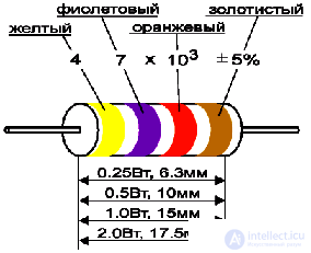
Fig. 13. Example of color coding of resistors and their overall dimensions depending on the allowable dissipated power.
An example of the color ring coding of resistors is shown in fig. 13.
Precision resistors are marked using a five-ring system.
In this case, the first ring corresponds to the first digit of the rating, the second - to the second digit, the third - to the third digit, the fourth - to the power of the multiplier of 10, and the fifth - to the tolerance.
Determining a resistor's rating should begin with the ring located closer to one of the resistor's ends, or the one that is wider than all the other rings.
In UPS circuits, you may encounter resistors whose markings differ from the standard. Such resistors either have no markings at all, or are marked with a single black ring.
The resistance of such resistors amounts to small fractions of an Ohm, and they are in fact resistors with almost zero resistance.
These resistors are installed in some UPS units at the most critical parts of the circuit and, in essence, perform the function of fuses.
When the current flowing through these resistors exceeds the allowable value, the resistor burns out (open-circuit state) and protects the circuit elements from failure.
In foreign literature, such resistors are known under the name SAFETY
RESISTORS (safety resistors).
Resistor faults encountered in practice can be divided into:
Despite the fact that cases of decreased nominal resistance of resistors are considered impossible in the technical literature, the authors have nevertheless encountered such cases in practice. Apparently, such faults are related to the manufacturing technology features of such resistors.
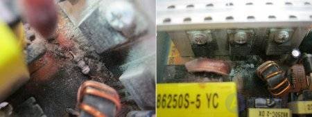
A resistor fault cannot always be determined by its external appearance (darkening, scorching, paint chipping off)!
In practice, there are frequent cases where a faulty resistor looks no different from a working one. In such cases, a faulty resistor can only be identified by ohmic "continuity testing" for compliance with its rating after unsoldering it from the circuit.
On the other hand, darkening of a resistor does not always mean it has failed. In addition, darkening of a resistor makes it difficult to determine its rating from the color code applied to its surface, since the colors of the rings become hard to distinguish from each other. In these cases, you can get around the problem either by obtaining the necessary information from the schematic diagram (if available), or from the rating of a similar resistor in a similar design.
When determining the ratings of low-power resistors with small dimensions, it is advisable to use a magnifying glass, since similar colors (for example, brown and violet; gray and silver; red and orange) are difficult to distinguish with the naked eye.
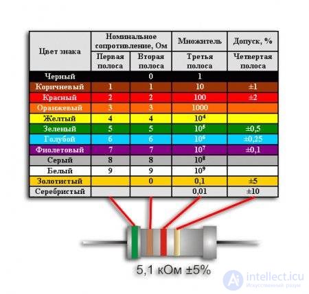
The resistor's rating is determined by the color coding. Resistors should only be replaced with identical ones, since a small difference in resistance ratings can cause the resistor to overheat. And if it is a pull-up resistor, the voltage in the circuit may go beyond the logic input limits, and the PWM will not generate a Power Good signal. If the resistor has burned to a crisp, and you don't have a second identical PSU to check its rating, then consider yourself out of luck. This is especially true for cheap PSUs, for which it is practically impossible to obtain schematic diagrams. Below is a table of resistor color coding:
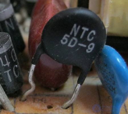
The purpose of the thermistor is to reduce the inrush current at power-on. When a high-voltage pulse occurs, the thermistor's resistance sharply decreases to fractions of an Ohm and shunts the load, protecting it and dissipating the absorbed energy in the form of heat. In the event of a mains overvoltage, the thermistor sharply decreases its resistance, and the increased current through it burns out the fuse. The other elements of the power supply unit remain intact.
The thermistor fails due to voltage surges, caused for example by a lightning storm. Thermistors also fail if you mistakenly switched the PSU to 110V operating mode. It is usually not difficult to identify a failed thermistor. It usually turns black and cracks, and soot appears on the surrounding elements. The fuse usually blows along with the thermistor. Fuse replacement can only be carried out after replacing the thermistor and checking the other elements of the primary circuit.
Capacitors are most often divided into categories according to the dielectric material from which they are made.
Note. Capacitors of various types have characteristics that make them suitable for some applications and unsuitable for others.
Failed capacitors are easily identified by bulging tops or leaked electrolyte. Capacitors are replaced with equivalent ones. Replacement with capacitors of slightly larger capacitance and voltage rating is permitted. If the capacitors in the standby power circuit have failed, the PSU will power on only after several attempts, or will refuse to power on at all. A PSU with failed output filter capacitors will shut down under load or will also completely refuse to power on, going into protection mode.
Sometimes dried-out, degraded capacitors fail with no visible damage. In such a case, the capacitors should first be desoldered and their capacitance and internal resistance checked. If there is nothing to check the capacitance with, replace all capacitors with ones known to be good.

A real capacitor is not a pure capacitance but also has resistance and inductance, as shown in the equivalent circuit in fig. 12, a. The inductance L is created both by the leads and by the structure of the capacitor itself; R2 is the parallel leakage resistance, and its value depends on the volume resistivity of the dielectric material; R1 is the effective (equivalent) series resistance of the capacitor, which depends on the dielectric loss tangent of the capacitor.
Note. One of the most important considerations when selecting a capacitor type is its operating frequency.
The maximum frequency at which a capacitor operates effectively is usually limited by the inductance of the capacitor and its leads.
At a certain frequency the capacitor has its own resonance with its inductance.
At frequencies above the self-resonant frequency, the capacitor exhibits inductive reactance that increases with frequency.
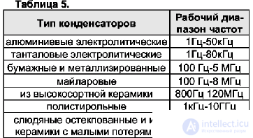
Table 5 gives approximate frequency ranges in which capacitors of various types can be used.
The upper frequency limit is determined by the capacitor's self-resonance or by the increase in loss tangent at high frequencies. The lower limit is determined by the maximum capacitance value achievable in practice.
Paper and Mylar capacitors are mid-frequency capacitors with relatively high series resistance and inductance.
They are usually used for filtering, bypassing and decoupling, as well as in timing circuits and noise suppression circuits.
Mica and ceramic capacitors have very low series resistance and inductance.
These are high-frequency capacitors typically used for high-frequency filtering, bypassing, as coupling and timing elements, and for frequency separation.
They are usually very stable over time, with temperature changes, and with voltage.
High-grade ceramic capacitors (with a high dielectric constant) are mid-frequency capacitors.
They are relatively unstable over time, with changes in temperature and frequency.
Their main advantage is a high capacitance per unit volume compared to standard ceramic capacitors.
They are usually used for bypassing, blocking and decoupling. One of the drawbacks of these capacitors is that transient voltages can cause damage to them.
Therefore, it is not recommended to use them as bypass capacitors connected directly between the power supply rails.
Polystyrene capacitors have exceptionally low series resistance and a very stable capacitance-frequency characteristic.
Of all the capacitor types listed, they are closest to an ideal capacitor.
Typical applications for them are filtering, bypassing, decoupling, timing circuits and noise suppression.
The characteristics of dry tantalum electrolytic capacitors are similar to those of aluminum electrolytic capacitors.
However, their series resistance is lower, and their capacitance per unit volume is higher than that of the latter.
Some solid tantalum capacitors have sufficiently low inductance and can be used at somewhat higher frequencies than aluminum electrolytics.
In general they are more stable over time with respect to temperature changes and shock loads than aluminum capacitors.
Special attention should be paid to aluminum electrolytic capacitors, as they are the components most prone to failure compared to other capacitor types.
The main advantage of an electrolytic capacitor, which accounts for its widespread use, is the large capacitance that can be obtained in a small package.
However, an aluminum electrolytic capacitor can have a series resistance of 1 ohm (a typical value is about 0.1 ohm). The series resistance value increases with rising frequency (due to dielectric losses) and with decreasing temperature.
Due to their large size, aluminum electrolytic capacitors also have high inductance, so they are low-frequency capacitors and are not recommended for use at frequencies above 30 kHz.
They are most often used for filtering, bypassing and decoupling at low frequencies.
When used at high frequencies, they must be bypassed with a low-capacitance capacitor having low self-inductance. This is necessary because the capacitance of an electrolytic capacitor falls as frequency increases.
For calculations, an empirical relationship can be used that gives a good approximation in the operating frequency range:
C = 0.77 ۰ Crated ۰ 0,001۰f
where Crated is the rated capacitance of the capacitor.
For example, a capacitor with a rated capacitance of 22uF at a frequency of 800Hz will represent an effective capacitance of only 5uF!
Therefore, to ensure quality filtering across the entire frequency range, an electrolytic capacitor must be bypassed with a high-frequency ceramic capacitor, since the capacitance of an electrolytic capacitor at high frequencies is very small.
One of the drawbacks of electrolytic capacitors is that they are polarized and must be maintained at a constant voltage of the correct polarity, i.e. the capacitor can only work with pulsating current and cannot work with alternating current.
In practice, breakdown of rectifier diodes is a frequent occurrence.
In such cases the capacitor becomes subjected to alternating current flowing through it in both directions.
This leads to rapid heating of the capacitor followed by failure and possible explosion.
Explosion of an electrolytic capacitor can cause injury!
Be careful when powering on a UPS under repair! Do not lean close to the circuit trying to "see" the processes taking place in it - this is dangerous! Only after you have made sure that no explosion occurred immediately upon power-on can you proceed to examine the circuit - by this time it will have heated up and be ready to blow... so wait a few seconds.
To extend the service life of electrolytic capacitors, they should operate at a voltage not exceeding 80% of the maximum rated working voltage.
By connecting two polar capacitors of equal capacitance in a back-to-back series configuration, a non-polar capacitor can be obtained that is capable of operating in AC circuits.
The resulting capacitance of such a capacitor equals half the capacitance of a single capacitor, and the permissible voltage equals the permissible voltage of a single capacitor.
When using electrolytic capacitors in AC or pulsating DC circuits, the ripple voltage must not exceed the maximum permissible value specified in reference materials.
Otherwise the capacitor will overheat. Temperature is the primary cause of aging, and therefore electrolytic capacitors should never be used at a temperature exceeding the value recommended for them.
This is precisely why the casing of a foreign-made electrolytic capacitor bears not only its rated value and working voltage, but also the maximum permissible operating temperature.
The capacitance of electrolytic capacitors is marked on their casing in units or fractions of a microfarad, for example: 100uF = 100uF, 2.2uF = 2.2uF.
The polarity of foreign-made electrolytic capacitors is marked with (-) symbols, located along the entire length of the capacitor casing on the side of its negative terminal.
Markings for capacitors of other types vary depending on the manufacturer. In addition, some manufacturers use coded designations for capacitor ratings.
The code consists of three digits and expresses the capacitor's rating in picofarads. The first two digits of the code are significant, and the third digit represents the power of the multiplier 10.
For example, if a capacitor bears the marking 472K, its rating is 47 x 100 = 4700pF.
Common capacitor faults encountered in practice can be divided into:
The condition of a capacitor can be checked by desoldering it from the circuit and testing it with an ohmmeter ("continuity/buzz test", for breakdown), as well as by measuring it with a capacitance meter (for open circuit and conformance to rating).
In doing so, it is recommended to set the maximum measurement range when using an analog (needle) ohmmeter.
The condition of electrolytic capacitors, due to their large capacitance, can be roughly estimated from the initial deflection of the ohmmeter needle. For comparison, it is useful to have on hand a known-good electrolytic capacitor of the same capacitance as the one being tested.
If the capacitor under test is good, the needle deflection should be approximately the same as for the reference capacitor. The polarity of the ohmmeter probe connections should match the polarity of the capacitor leads ((+) of the ohmmeter to the lead of the capacitor's positive plate).
With a good capacitor, the ohmmeter needle, after deflecting, should slowly return to the start of the scale.
If this does not happen and the needle stops well short of the start of the scale, the capacitor under test has an elevated leakage value and should be replaced.
Do not forget to discharge the capacitor before testing it by briefly shorting the leads with a screwdriver or tweezers! Otherwise you risk damaging your measuring instrument.
Detecting such capacitors presents a particular difficulty during repair.
Desoldering and testing with an ohmmeter does not produce a result in these cases.
Such a capacitor can only be detected by a disruption of the circuit's operating mode at the location where it is installed.
In such cases, it is best to replace the suspected capacitor with a known-good one, or to build a special test circuit to check it under voltage.
Sometimes there are cases where, as a result of careless handling of a board, ceramic capacitors mounted on it sustain mechanical damage.
Such capacitors immediately catch the eye during a careful inspection of the board.
They have chipped edges, cracks, etc. Even though they may still be functional, such capacitors are best replaced right away.
These are special cases of inductors with a magnetic core.
In a real coil, the wire it is wound from has a series resistance, and there is a distributed capacitance between the turns of the winding.
Two inductors coupled to each other through a common magnetic core form a transformer.
Real transformers (unlike ideal ones) have capacitance between the secondary and primary windings.
The equivalent circuit of an inductor is shown in fig.12,6. The interturn capacitance is represented here as a shunting capacitor with lumped parameters, so that at a certain frequency there is a parallel resonance.
This resonant frequency determines the upper frequency at which the inductor can be used.
Another important characteristic of inductors is their sensitivity to stray magnetic fields and their ability to generate such fields.
Therefore, power pulse transformers of UPS units are subject to strict requirements for ensuring electromagnetic compatibility, for winding leakage inductance while ensuring good flux linkage between windings, and also for a design with high insulation strength (as a rule, the breakdown voltage is at least 2kV). These requirements are primarily due to the rectangular shape of the voltage waveform at a high frequency (about 30kHz), as well as the large amplitude of the pulses in each half-period of the voltage.
Pulse transformers are designed to transmit short-duration electrical pulses of fairly high power.
The resulting distortion of the flat part of the pulse is determined by the finite value of the primary winding inductance L1, while the distortion of the leading edge is determined by the leakage inductance Ls.
These pulse edge distortions are caused by parasitic oscillations arising in the circuit formed by the leakage inductance Ls and the self-capacitance C0.
Therefore, when designing a pulse transformer, special measures are taken to reduce these parasitic parameters.
These measures mainly come down to the following.
The windings are arranged in such a way that during operation the smallest possible pulse voltage is applied between their leads. It is recommended to place the winding with fewer turns on the inside, and the winding with more turns on the outside of the coil.
To obtain a low value of leakage inductance, one of the windings is wound in two layers, between which the second winding is placed.
In some pulse transformers, the primary and secondary windings are wound simultaneously with two wires, so that the turns of one winding are located between the turns of the other.
Films of inorganic dielectrics are usually used as interlayer and interwinding insulation.
The transformers themselves are impregnated with compounds or varnishes.
In the power pulse transformers of personal computer PSU units, E-shaped (E-shaped) ferrite cores are widely used, as they are the most manufacturable for the winding process and are characterized by a high fill factor.
Based on the above, an unfortunate conclusion can be drawn: when a power pulse transformer fails, repairing it or manufacturing a new one is a very complex matter that requires special equipment, materials, tooling, and high qualification.
In addition, a pulse transformer is an original, non-standardized part that is designed and used for a specific PSU circuit and, as a rule, is not suitable for other circuits.
If even one of the above parameters is violated as a result of repairing a pulse transformer, it will perform unsatisfactorily, which leads to disruption of the optimal ratio of power losses across the PSU elements and to a rapid repeat failure of the UPS.
Fortunately, power pulse transformers fail irreversibly quite rarely, which is explained by their high reliability, built into their manufacturing technology, since the pulse transformer is one of the most critical elements of the UPS circuit.
Let us now consider the main design features of current transformers, which are used in many UPS circuits as the sensor of the current protection circuit.
A characteristic feature of a current transformer, unlike a voltage transformer, is that its secondary winding must always be closed onto a load whose resistance does not exceed a certain value.
An open state of the secondary winding is an emergency mode. Let us explain this in more detail.
Since the primary winding current does not change when the secondary winding circuit is broken, unlike in a voltage transformer, the alternating magnetic flux in the core has a very large amplitude, because there is no opposing compensating magnetic flux generated by the secondary winding current.
The rate of change of the magnetic flux when the polarity of the current flowing through the primary winding reverses is also very high.
Therefore, the EMF induced by this flux on the open secondary winding will be very high. The magnitude of this EMF is such that it can cause insulation breakdown.
For safety in the event of insulation damage between the primary and secondary windings, the secondary winding must always be grounded.
In addition, the large amplitude of the alternating magnetic flux in the core leads to a significant increase in core remagnetization losses. Therefore, the transformer begins to overheat significantly.
In the PS-6220C UPS circuit, for example, the function of the load for the secondary winding of current transformer T4 is performed by resistor R42 (470 Ohm). The current transformer in this class of UPS generally has two design implementations. In one variant, it is a transformer on an E-shaped (E-shaped) ferrite core, on the center leg of which a bobbin with the secondary winding wound on it is located. The primary winding is located over the secondary winding and consists of a single turn of mounting wire in plastic insulation (fig.14, a, b).
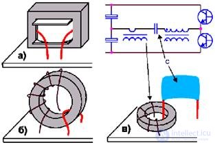
Fig.14. Current transformer designs encountered in practice on an E-shaped (E-shaped) (a) and on a toroidal (b, c) core.
In another variant, the secondary winding is wound on a toroidal ferrite core, and the primary winding is the lead of a capacitor that is connected in series with the primary winding of the power transformer (fig.14, c).
However, other design variants of the current transformer are also encountered.
The output filter chokes (except for the group stabilization choke) are inductors with a single-layer winding of large-cross-section copper wire on an open cylindrical ferrite core (ferrite rods).
The large wire cross-section is due to the significant value of the UPS output currents, and the open core shape is due to the choke operating with a large bias (magnetization) current.
A closed core shape in this case would lead to the core entering magnetic saturation and the choke losing its filtering properties.
Faults in inductive elements can be divided into:
Failure of output filter chokes in a UPS is an extremely rare occurrence due to their high reliability.
Failure of transformers can often be determined by visual inspection from darkening of individual areas of the outer insulation, the appearance of air bubbles under the insulation, foaming, and the seepage of impregnating compound from under the insulation.
The integrity of the windings for an "open circuit," as well as the presence of an interwinding short circuit and a short circuit of any winding to the core, are easily checked using ohmic "continuity testing."
The rest of the faults listed above are extremely difficult to detect, since the ohmic resistance of the transformer windings is very small (units and even fractions of an Ohm!).
If there is a suspicion of an interturn short circuit or a loss of magnetic properties by the core, then the transformer needs to be replaced with an identical one.
Fault and diagnostics of the group stabilization choke (GSC).
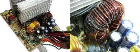
It fails due to overheating (when the fan stops) or due to design flaws in the PSU itself (example: Microlab 420W). A burnt-out GSC is easily identified by darkened, flaking, charred insulating varnish. A burnt-out GSC can be replaced with an identical one or a new one can be wound. If you decide to wind a new GSC, you should use a new ferrite ring, since due to overheating the old ring's parameters could have drifted.
продолжение следует...
Часть 1 General Questions on Repairing Uninterruptible Power Supplies (UPS)
Часть 2 9.4 Diagnosing and testing diodes and Zener diodes - General

Comments