
Lecture
Based on operating experience, a list of the most commonly encountered characteristic defects of electrical machines can be given.
Stator core:
- damage to inter-laminar insulation, causing local overheating;
- loosening of the core pressing, causing vibration of the steel laminations with damage to the inter-laminar insulation; splaying of the end packets, causing sheet cracking;
- change in the shape of the stator of hydrogenerators due to loosening of the joints between stator sectors, which can lead to rotor-to-stator rubbing.
Stator winding:
- loosening of the bar fastening in the slot, causing abrasion of the bar insulation;
- damage to the semiconducting coating of the bar, causing the appearance of partial discharges (PD); delamination of the insulation, causing its accelerated aging;
- breakdown of the insulation of the elementary conductors, causing an increase in circulating currents and local overheating of the winding;
- loosening of the end-winding fastening, causing abrasion of the insulation, displacement of the conductors and increased vibration of the end windings;
- contamination, oiling and moistening of the insulation, causing a reduction in the dielectric strength of the insulation;
- cracks in the insulation, leading to a reduction in its dielectric strength.
- for machines with direct water cooling, a very dangerous defect is moistening of the insulation due to loss of tightness of the cooling system, causing breakdown in the bar zone at the slot exit.
Direct cooling system:
- blockage of the direct cooling channels, leading to local overheating of the winding;
- loss of tightness, leading to the appearance of distillate inside the housing and moistening of the insulation.
Rotor:
- cracks in various parts of the turbogenerator rotor or the hydrogenerator shaft, leading to increased vibration at the rotational frequency and a change in vibration phase;
- loss of integrity of the retaining rings and wedges of the rotor winding, leading to increased vibration.
Field winding:
- damage to the ground-wall insulation and turn-to-turn short circuits, leading to increased vibration at the rotational frequency and the appearance of bearing currents;
- wear of the hollow conductors under water cooling, leading to thermal imbalance of the rotor and increased vibration.
Air gap (for hydrogenerators and large induction motors):
- change in the shape of the gap or in the coaxiality of the stator and rotor cores, leading to current asymmetry in parallel branches and to possible rotor-to-stator rubbing with subsequent destruction of the latter.
Bearings and thrust bearings:
- breakdown of insulation, leading to the appearance of bearing currents and increased bearing heating;
- wear of the working surfaces and misalignment, which also lead to an increase in temperature and vibration level.
Rotor shaft seals (for hydrogen-cooled turbogenerators):
- wear of the seals or their damage, leading to an increase in hydrogen consumption and ingress of oil inside the housing;
- misalignment of the seals, leading to their increased heating.
Means and methods for monitoring the condition of individual components. Stator core. Loosening of the core pressing leads to increased vibration, which is monitored by special sensors mounted on the machine housing. Damage to the inter-laminar insulation leads to local overheating, which is monitored either by temperature sensors installed in the active steel of the stator, or by thermal imagers, or with the help of special thermal indicator coatings. These coatings are applied to the surface of machine components that are critical with respect to overheating, and upon reaching the limiting temperature they release certain gases and aerosols, which are detected by chemical analysis of the cooling gas. Coatings of different chemical composition are applied to different machine components, which makes it possible not only to record local overheating but also to identify its sources. In addition to coatings, thermosensitive "labels" can be installed at hazardous locations, changing their color when the threshold temperature of the installation site is exceeded. Inspection of the "labels" is possible only during an overhaul of the stopped machine.
Stator winding. Monitoring of the thermal condition of the winding is carried out either with the help of built-in temperature sensors, or with the help of thermal imagers, or by chemical analysis of the cooling gas, which contains products of thermal decomposition of the insulation. The concentration of decomposition products can be used to judge the degree of insulation overheating. Monitoring of local overheating can be carried out by applying thermal indicator coatings or thermosensitive "labels".
Monitoring of insulation condition is carried out by PD analyzers, which measure the intensity of partial discharges. Signals are fed to the analyzer from capacitive coupling sensors installed under the slot wedge. Existing PD analyzers make it possible to recognize the following defects of the stator winding: loosening of the winding fastening in the slot, damage to the semiconducting coating, delamination or poor impregnation of the insulation, separation of copper from the ground-wall insulation, significant wear of the insulation, loosening of the winding fastening. Due to their high informativeness, PD analyzers have become widely used in diagnostic systems for large electrical machines.
Partial discharges lead to the appearance of ozone in the cooling gas. A high concentration of ozone indicates the presence of partial discharges in the insulation, associated with damage to the semiconducting coating.
Air gap. Monitoring of the air gap is carried out using optical monitoring systems having an accuracy of 0.05 mm at a measurement limit of 40 mm. With the help of such systems, having sensors on the stator and rotor, it is possible to detect radial oscillations of the stator, uneven expansion of the stator during heating, dynamic changes in the air gap during changes in operating mode, and shaft runout.
Recently, capacitive-sensor-based systems for monitoring the air gap of hydrogenerators have become widely used. They are simpler than optical systems and make it possible to manage with only sensors installed on the stator.
Bearings and thrust bearings. To determine the condition of bearings, either direct thermal monitoring (by installing sensors on the babbitt liners) or indirect thermal monitoring (measuring the oil temperature at the bearing inlet and outlet) is carried out, as well as vibration monitoring.
Separately, mention should be made of vibration diagnostic systems, which are now widely used. These systems make it possible to obtain reliable information on the presence of the following defects: rotor imbalance, shaft misalignment, air gap non-uniformity, seal defects, cracks in the rotor, structural resonances, and a number of others.
Based on a set of defect detection methods, automated systems for monitoring the condition of large electrical machines have been created. Thus, the SKDG system created in Russia monitors temperature, electrical and mechanical parameters and issues warning and emergency signals when the measured values go beyond permissible limits. The system has 120 monitoring channels, processes and stores measurement data and operating mode indicators.
The main direction of development of diagnostic systems is automation. An example of automated systems is the SUPER system, installed at one of the Canadian hydroelectric power plants.
The SUPER system records 52 mechanical and 10 electrical parameters every minute and contains 50 alarm settings. Data is normally transmitted to the main processor once an hour. In the event that any of the settings is triggered (an alarm signal - the monitored parameter going beyond permissible limits), data for the preceding hour of operation is transmitted to the processor. The software makes it possible to process and transmit sensor signals, select them for the database, carry out continuous "on-line" monitoring and analysis, and conduct special tests.
In functional diagnostic systems, devices for monitoring chemical and mechanical impurities in the cooling gas have found wide application, making it possible to determine insulation overheating (from the products of its thermal degradation or from the decomposition products of thermosensitive coatings) and the degree of its mechanical wear (from the composition and quantity of mechanical impurities). These devices can be either stationary (for continuous monitoring of insulation condition) or portable (for periodic monitoring of insulation condition).
The use of functional diagnostic systems together with tests and inspections during overhauls and inspections makes it possible to maximize the interval between repairs, and, when repair is necessary, to more precisely determine the location and extent of the damage, thereby minimizing its scope and the time required for the repair.
Electromagnetic defects of electrical machines. By analyzing signals from vibration sensors installed on the bearings of electrical machines, it is possible to identify quite a number of specific causes of increased vibration that occur only in electric motors and generators of various types. These causes can be either a direct result of the presence of various internal electromagnetic defects of electrical machines, or simply related to specific features of the manifestation of electromagnetic processes in windings and cores, reflecting the features of normal operation of electric motors and generators in units.
Vibration diagnostic methods for monitoring the condition of motors and generators are usually the first stage in condition assessment, since they make it possible to analyze the condition of equipment directly during its operation. After identifying, with the help of vibration diagnostics, the main characteristic signs of the existence of a particular defect, it is necessary to apply other, specialized diagnostic methods.
Common, widespread causes of increased vibration of electrical machines "of a non-electromagnetic nature", such as imbalance, bearing defects, etc., do not differ from the well-studied causes of vibration of rotary process equipment - pumps, compressors, fans. Therefore, the main attention will be paid to the causes of increased vibration due to defects of electrical machines of an electromagnetic nature. The main methods of diagnosing AC machines, synchronous and asynchronous, as the most widespread in industry, will be considered.
Part of the vibration in electrical machines is excited by the forces of electromagnetic interaction between the elements of the machine - the forces of magnetic attraction between the elements of the core and the forces between the elements of the windings carrying currents. The main, or, in the terms adopted in spectral vibration diagnostics, the rotational frequency of the electromagnetic forces and vibrations is equal to twice the frequency of the supply mains. This follows mathematically from the fact that magnetic processes are proportional to the square of the "sine wave" of the supply mains, and this is precisely an oscillation at twice the frequency of the original. This is a completely separate force, not related to the rotor rotation frequency. It simply has a frequency equal to twice the frequency of the supply mains. The harmonics of the fundamental frequency of this force have values of 200 Hz, 300, 400, etc. In its pure form, this force is very clearly manifested in static electrical equipment. An example of this is a transformer, in which the vibration harmonic at the supply frequency of 50 Hz is practically absent, while the harmonic at a frequency of 100 Hz is maximal.
Vibrations in AC motors and generators, in the general case, can be caused, mainly, by five forces of electromagnetic nature, having their own frequencies:
- the first force is related to the frequency of the supply mains F1, has a peak at a frequency of 50 Hz;
- the second force FEM generates oscillations at the frequency of manifestation of electromagnetic processes in the copper and steel of the electrical machine, has a peak at a frequency of 100 Hz, manifests itself in vibration of the core and windings of all AC machines;
- the third is related to the rotation frequency of the electromagnetic field in the gap of the electrical machine and is the quotient of the supply mains frequency divided by the number of stator pole pairs F0 = (F1 / P). In synchronous machines this is the rotor rotation frequency;
- the fourth FP is related to the rotor rotation frequency and in asynchronous machines is always a few percent lower than the rotation frequency of the electromagnetic field. In synchronous machines these two forces excite oscillations at one and the same frequency, which follows directly from the operating principle of the synchronous machine;
- the fifth Fsl is caused by the presence of a slot-tooth structure in the gap of the electrical machine. Vibration can be proportional to the product of the rotation frequency and the number of stator slots, rotor slots, or their beat frequency. An indirect manifestation of the influence of the slots is asymmetry of the rotor of a non-salient-pole turbogenerator, when one part of the rotor has slots and the other does not. As a result, rotor deflection differs when it is turned by 90 degrees. This always leads, at a rotor rotation frequency of 50 Hz, to increased vibrations in the vertical direction at a frequency of 100 Hz.
The main sign that the diagnosed defect has an electromagnetic nature is the instantaneous disappearance of its signs in the vibration spectrum after the electrical machine is disconnected from the mains.
It is very important that diagnosis of the causes of increased vibration of electrical machines be carried out at the highest possible motor load. If the studies are carried out at no load, then very often it is only possible to detect a small fraction of all the electromagnetic defects present in the equipment.
For successful diagnosis of various electromagnetic defects in electric motors and generators, a spectrum analyzer with very high resolution is required, with a number of spectral lines of not less than 3200.
Vibration measurement on the bearings of electric motors and generators must always be carried out in three directions - vertical, transverse and axial, otherwise it will subsequently be impossible to carry out a complete diagnosis of the condition. Ideal is synchronous recording (not to be confused with synchronized recording, which is much less effective) of all six vibration signals from the two bearings of the electrical machine at once. This usually increases the reliability of diagnoses by an additional not less than 10%.
List of electromagnetic defects. Let us give a brief list of electromagnetic defects of electrical machines that can be effectively diagnosed from vibration signal spectra. Here we also give all the characteristic signs of each type of defect.
To describe defects we will use the terms:
- F1 - supply mains frequency 50 Hz;
- FEM - frequency of electromagnetic forces in electrical machines, equal to twice the mains frequency, 100 Hz;
- N0 - rotation frequency of the field in the gap of the electrical machine, numerically equal to the quotient of 3000 divided by the number of pole pairs “P”, which can take integer values from one and above (rpm);
- F0 - electromagnetic field frequency in the gap (Hz);
- NP - natural rotation frequency of the rotor of the electrical machine, for synchronous machines it coincides with the field rotation frequency, for asynchronous machines it is always lower by the amount of slip;
- s - slip of the rotor relative to the electromagnetic field in asynchronous machines, a dimensionless quantity, numerically equal to the difference between the rotation frequency of the field in the gap and the rotation frequency of the rotor, referred to the rotation frequency of the field in the gap s = (N0 - NP ) / N0;
- FP - rotor rotation frequency, for synchronous machines numerically equal to the rotation frequency of the field in the gap, and for asynchronous machines always lower than the rotation frequency of the field by the amount of the product of the field rotation frequency and the rotor slip FP = F0 (1 - s);
- Fsl - slot-tooth vibration frequency, numerically equal to the product of the number of slots (on the rotor or stator) and the frequency of the electromagnetic field in the gap. It may be elevated relative to the stator, relative to the rotor, and may be the difference or sum beat frequency of the rotor and stator slot frequencies.
The most dangerous stator defects, which can be determined from vibration parameters:
- loosening of the steel lamination stack pressing, break or short circuit in the winding. Manifest at the frequency of action of the electromagnetic forces FEM, equal to twice the supply mains frequency. Special attention should be paid to the presence of fractional harmonics of the electromagnetic frequency - 1/2, 3/2, 5/2, etc. of the fundamental frequency. In terms of frequency value, these harmonics correspond to the fundamental and odd harmonics of the supply mains;
- eccentricity, ellipticity, of the internal bore of the stator relative to the rotor rotation axis. Usually arises as a bearing pedestal installation defect, a defect in the condition of the bearing shields, or as a result of stator deformation. In vibration it manifests itself at the field rotation frequency in the gap and at the electromagnetic force frequency of 100 Hz. Sometimes accompanied by the appearance of side harmonics. Usually accompanied by inequality of the vertical and transverse components of the corresponding harmonics. The spatial maximum of the harmonics corresponds to the direction of the eccentricity, the displacement of the stator axis. It is most easily diagnosed by taking a “vibration rose”, when the sensor is successively moved along an envelope around the bearing, with a shift at each measurement by an angle of 30 - 45 degrees;
- incorrect mutual axial mounting of the active rotor and stator stacks. Sometimes the term “incorrect setting of electromagnetic axial float” is used for this defect. During operation of the electrical machine, as a result of magnetic attraction forces, the rotor stack always tends toward a position exactly under the stator stack. If this is prevented by the bearing mounting conditions, then in an incorrectly installed bearing, shifted in the axial direction, axial loads and vibrations will arise. The bearings will heat up fairly quickly and fail. Sometimes the motor rotor is “pulled” in the axial direction by the shaft of the mechanism, which is possible with incorrect axial mounting of the entire mechanism and in the case of low mobility in the coupling.
Main rotor defects diagnosed from vibration:
- eccentricity of the outer surface of the rotor relative to its rotation axis. In the vibration signal spectrum this defect manifests itself in amplification of the first harmonic of the rotor rotation frequency. The frequency of action of the electromagnetic force is amplified, around which side harmonics sometimes appear, shifted from each other by the rotor slip frequency multiplied by the number of poles;
- break or loss of contact in the bars or rings of the “squirrel cage” in an asynchronous motor. Usually manifests itself near the rotor shaft rotation frequency and is always accompanied by the appearance of sidebands shifted relative to the harmonic of the rotor rotation frequency by an interval equal to the product of the slip frequency and the number of motor poles;
- loosening of the pressing of the entire rotor steel stack or only in the tooth area. Accompanied by amplification of the second harmonic of the supply mains, or, when the steel is loosened in the tooth area, by the appearance of the rotor slot frequency with sidebands shifted from each other by a frequency equal to twice the supply frequency.
Defects of stator steel and copper. With all defects of the active steel or winding of the stator of a synchronous or asynchronous electrical machine that have an electromagnetic nature, a specific pattern arises in the vibration signal spectrum. This is mainly vibration with a high-amplitude harmonic at the frequency of electromagnetic processes FEM. As already mentioned above, its frequency is equal to the second harmonic of the supply mains frequency, i.e. equal to 100 Hz.
This is quite well explained from the point of view of the physics of the processes taking place. The mutual attraction forces acting between “unpressed” sheets of electrical steel or elements fastening the steel stack have an amplitude maximum twice during one period of change of the supply mains - during the minimum and maximum of the magnetic flux. The picture of interaction between the elements of the stator winding looks similar. Mathematically this is explained by the fact that electromagnetic forces are proportional to the square of the current or magnetic flux. Since both are sinusoidal, their product is also proportional to a sinusoid, but one that changes at twice the frequency relative to the original supply mains frequency.
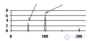
In the vibration signal spectrum shown in Figure 8.1, the picture of the occurrence of electromagnetic problems in the stator is expressed in amplification of the peak at the electromagnetic frequency. With significant steel defects, the second (200 Hz) harmonic of the FEM frequency and the third (300) may also appear, as well as a number of fractional harmonics which, in this situation, numerically correspond in frequency to the synchronous, whole odd harmonics of the supply mains frequency.
|
Figure 8.1 – Vibration spectrum in the presence of stator defects |
Vibration harmonics from electromagnetic processes in the stator of a synchronous machine, by their physical nature, are synchronous relative to the rotor rotation frequency. In an asynchronous motor these same harmonics are non-synchronous, since the rotor rotation frequency and the supply mains frequency are not multiples of each other, and differ from each other in proportion to the slip frequency.
Loosening of the pressing of the active stator iron is caused, mainly, by two reasons - either general loosening of the stator iron fastening elements, or the phenomenon of “delamination” of the outer sheets and steel stacks.
When localizing a stator iron defect, the installation location of the vibration sensor begins to play an important role. The closer it is installed to the defective location of the stator stack, the shorter the path traveled by useful vibration information, the more correctly diagnosis can be carried out and the location of the defect manifestation localized.
The situation is similar with the features of manifestation in vibration signal spectra of various stator winding defects, but their search and localization are much more complex.
It should be remembered that distinguishing the type of defect being diagnosed in the stator - whether it has an “electrical nature”, or whether it is caused purely by “magnetic phenomena”, is quite difficult using spectral vibration diagnostics methods. The only, fairly reliable sign of the presence of a shorted turn in the stator is the presence of a side harmonic near a frequency of 100 Hz. In most practical cases it is necessary to apply more specialized methods for diagnosing the condition of electrical machines.
Stator eccentricity. Stator eccentricity most often arises as a manufacturing defect of the “laminated” stator steel stack, as a stator installation defect. The probability of stator eccentricity occurring during installation of the electrical machine is very high, especially if the stator and bearing supports are installed separately. This stator defect can arise as a result of foundation loosening, or as a result of thermal and other deformations in the unit and foundation.
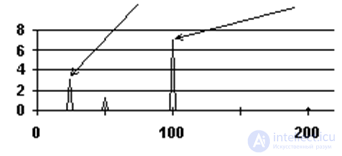
As an example, Figure 8.2 shows the spectrum of a vibration signal recorded on the bearing of an asynchronous motor having a nominal rotor rotation frequency equal to n0 = 1480 rpm.
This spectrum corresponds to the presence in the electrical machine of a fairly developed defect of the “stator eccentricity” type.
Stator eccentricity, from the standpoint of the physics of electromagnetic processes, leads to a periodic change in the magnetic conductance of the air gap, to its pulsation, or, in other words, to its modulation. This pulsation occurs at double the mains frequency, i.e. at the frequency of the electromagnetic force action.
|
Figure 8.2 – Vibration spectrum with rotor eccentricity |
The doubling of the pulsation frequency relative to the supply mains occurs because the north and south poles of the field rotating in the gap alternately pass by the zone of the stator circumference where the gap value has changed. The doubled pulsations of magnetic conductance lead to the same pulsation of the magnetic flux and, as a result, to pulsation of the electromagnetic force and vibration at a frequency of 100 Hz.
Additionally, the amplitude of the harmonic at the rotation frequency of the electromagnetic field in the gap increases somewhat. This allows, in induction motors, to well differentiate stator eccentricity from rotor eccentricity, where vibration occurs at the rotor rotation frequency. To reveal this distinction, a spectrum analyzer with good resolution is required.
To separate stator and rotor eccentricities in a synchronous machine from each other, during diagnostics it should be remembered that stator eccentricity is stationary in space and differs in vibration amplitude across different measurement projections. Due to this localization, stator eccentricity leads to the occurrence of vibration directed in space. This can be detected by sequentially moving the vibration sensor around the monitored bearing “around the shaft”. Rotor eccentricity, on the other hand, always “rotates” together with the rotor, so it does not have a stationary maximum at a particular sensor mounting angle. With stator eccentricity, such a maximum is clearly expressed.
To exclude the manifestation of eccentricity in the vibration of electrical machines, it is necessary that the air gap between the stator and rotor be uniform around the circumference. It must be carefully controlled during installation.
The requirement for the quality of mutual installation of the stator and rotor must be strictly observed; the difference in air gap value along the circumference must not exceed 5% for induction motors and generators, and must not exceed 10% for synchronous motors. The value of this parameter is strictly controlled using special feeler gauges during installation of the electrical machine. Such a measurement procedure should be performed at several mutual positions of the rotor and stator.
Broken rotor bars. The most common design of an induction motor rotor is a squirrel-cage rotor. In such a rotor, copper or brass bars are driven into the slots without insulation, or the slots are filled with aluminum alloy. The ends of the bars are joined by short-circuiting rings of the same material. During operation, a large current flows through the bars, and they heat up significantly, especially during starting. A common cause of motor failure is burnout of bars, which leads to increased load on the remaining bars, their overheating and burnout, and so on. The process ends with an “avalanche-like” failure of the motor.
Detecting the initial phases of the onset of the “burnout” process of squirrel-cage rotor bars is a very relevant task and makes it possible to improve the reliability of induction motors with a squirrel-cage rotor.
Let us consider the features of physical processes in a rotor that has characteristic spectral features typical of at least the initial stage of this defect – one burned-out bar.
It should be said right away that the spectrum of a motor with a burned-out bar largely resembles the spectrum of a motor with an eccentric rotor. At first glance there is little in common between these defects, but on closer examination similarities can be found.
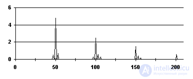
As with an eccentric rotor, a burned-out bar leads to modulation of the motor's tractive force. At the moment the zone of the burned-out bar passes by the pole, the tractive force abruptly decreases, and the rotor slows down slightly. At this time, the zone of a defect-free bar approaches the pole, in which, due to increased slip, there will be a greater current, the tractive force will increase, and the rotor will accelerate slightly. These mini-accelerations and mini-decelerations will be characterized in the spectrum by the appearance of teeth around the main harmonic of the rotor rotation frequency. Such a spectrum for a motor with a rotor rotation frequency of 2920 rpm is shown in Figure 8.3.
|
Figure 8.3 – Vibration spectrum with burned-out bars present in the squirrel-cage rotor
|
It is possible to separate these two causes – rotor eccentricity and burned-out squirrel-cage bars – but only with a good spectrum analyzer. The difference in their manifestations is as follows: - the characteristic “corona” of teeth around the peak of the electromagnetic frequency FEM manifests differently – with rotor eccentricity it is present in all modes, while with burned-out bars it appears only under significant load;
- with rotor eccentricity the “corona” is practically symmetrical in the magnitude of the mini-peaks relative to the central peak, while with a burned-out bar under load the peak at the lower frequency is always smaller than the “mirror” peak at the higher frequency. This fact agrees quite well with the picture of the physical processes. The decrease in speed occurs at normal slip and normal current in the last “good” bar of the cage. Acceleration occurs at increased slip, higher current in the first “good” bar and, as a result, with greater intensity;
- due to the oscillatory “settling” of the rotor after passing the defective bar, several harmonics of the rotor rotation frequency may appear in the spectrum, and usually all of them are surrounded by “coronas”.
As a numerical limit for the degree of manifestation of this defect, it can be considered that a “corona” should not be present in a healthy motor. If it appears and, under load, the largest peak of the “corona” exceeds 10% of the central peak – the probability of burned-out bars being present is very high. To monitor the numerical value of the defect, it is better to use spectra with a logarithmic amplitude scale. If in this case the “corona” peaks are less than the main peak by less than 20 dB, then the defect is present.
In conclusion, emphasizing the features of diagnosing this cause of increased vibration, it must be pointed out once again that such diagnostics is only possible using spectrum analyzers with high resolving power. This is needed to separate, on the spectrum, the field rotation frequency, the rotor frequency, and the sideband harmonics. The central peak of the “corona” should correspond to the rotor rotation frequency, and not be equal to the rotation frequency of the field in the gap.
Tooth-slot structure defects. This fault is not very common in practice, but nevertheless it can be described and diagnosed.
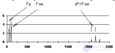
This fault can be conditionally represented as a rotor lacking one ferromagnetic tooth. This leads to the fact that a magnetically non-periodic element moves past the stator slots, inducing pulses in the stator winding, the number of which per revolution will be numerically equal to the number of stator slots. On the spectrum this will be represented by a peak at a frequency equal to the product of the rotor rotation frequency and the number of stator slots.
|
Figure 8.4 – Vibration spectrum with tooth-slot structure defects present |
Without going into the details of the physical description, it should also be said that the defective tooth will also modulate the electromagnetic force of the stator. This is because twice per revolution the rotating field will “run into” a defect in the magnetic conductance of the motor's air gap, into the “missing” rotor tooth. On the spectrum, near the peak of the slot frequency, two mirror-positioned peaks will appear, shifted relative to their “main peak” by the electromagnetic force frequency FEM, which, as has been repeatedly stated, equals twice the supply mains frequency (Figure 8.4).
If defects are present in the tooth-slot structure of the stator, vibration may be registered at a frequency equal to the product of the number of rotor slots and the rotor rotation frequency, since the magnetic defect of the stator will be moving relative to the rotor. Everything else, including the occurrence of “mirror” peaks around the slot frequency, remains unchanged.
The most difficult spectrum to diagnose will be one with magnetic defects present on both the rotor and stator simultaneously, with multiple defects. The spectrum will contain the tooth frequencies of the rotor and stator, their beat frequencies, multiple “mirror” peaks, and so on.
The “positive” aspect in this case is that with such a defect the tractive force usually drops sharply, the consumed current increases, and the motor fails very quickly, usually sooner than personnel manage to record spectra and detect the multiple magnetic defect using vibration diagnostic methods.
Technical means of vibration diagnostics. To create vibration monitoring, diagnostics and balancing systems, appropriate technical means are required. The typical structure of a system based on the analysis of vibration parameters of electrical machines consists of the following main elements:
- vibration sensors;
- instrument for measuring and analyzing vibration;
- personal computer;
- software package for monitoring, in-depth diagnostics and forecasting the condition of equipment;
- communication lines from sensors to signal analysis equipment, from instruments to computers, from computers to computer networks;
switching and amplification devices.
The most specific element of such a system is the vibration analyzer. Let us consider the main parameters and functional purpose of this system element.
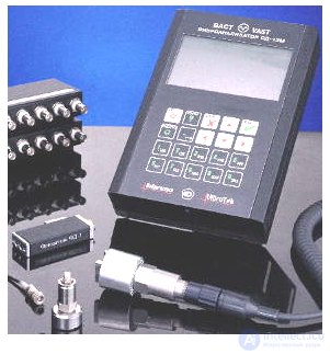
SD-12M vibration analyzer is designed for measuring, collecting and analyzing vibration parameters for the purpose of monitoring and diagnosing the technical condition of industrial equipment. For monitoring and diagnostic purposes, the following parameters are measured:
- vibration level, in bands specified by GOST standards;
- time signal (oscilloscope mode);
- signal spectra;
|
Figure 8.5 - SD-12M vibration analyzer
|
- envelope spectra of signal components extracted by bandpass filters;
- rotation speed;
- amplitude and phase of the signal at the rotation frequency and its harmonics;
- amplitude and phase of the signal during coast-down as a function of rotation frequency.
For rotor balancing:
- vibration measurements for balancing at 1–8 points;
automatic calculation of balancing masses in 1–3 planes.
The collected data can be entered into a computer for further processing and storage.
SD-12M is a fully digital spectrum analyzer and data collector with extended capabilities and a full set of vibration measurements, certified to a number of GOST and ISO standards (Figure 8.5). The instrument was developed specifically for use by personnel servicing equipment under industrial conditions. The SD-12M has remote control functions, including via modem, using standard communication lines. When equipped with the appropriate sensors, the vibration analyzer can be used both independently and as part of software-hardware complexes for monitoring and diagnosing industrial equipment by temperature, electrical parameters, and rotational speed.
The SD-12M vibration analyzer works with the DREAM for Windows and VBAL for Windows software packages. The measured vibration parameters are: vibration displacement, vibration velocity, vibration acceleration, and crest factor.
|
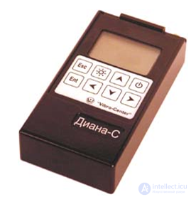
Figure 8.6 – Diana-S vibration signal collector-analyzer |
The Diana-S vibration signal collector-analyzer is designed for collecting and storing information (vibration signals, spectra, RMS values) in memory during route-based measurements. The instrument can also be used as a regular vibration signal analyzer (Figure 8.6).
The computing core of the instrument is implemented on a RISC processor. The Diana-S has a large amount of RAM for storing the current measurement. For example, when recording signals in the standard frequency range up to 1000 Hz, the duration of continuous recording can reach up to 100 seconds. The internal
|
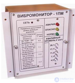
Figure 8.7 - Vibration monitor - 1PM |
non-volatile memory of the instrument is sufficient for storing several thousand signals or spectra. Loading of routes and unloading of data is carried out via a USB communication port. The use of this modern communication protocol in the instrument is necessary due to the increased volume of vibration signal storage memory. The Diana-S has one vibration monitoring channel.
Routes for the instrument are created on a computer using the "Atlant" software supplied with the instrument, or other software agreed upon with the manufacturer. Several routes can be loaded into the instrument at the same time. Registration of vibration signals "on route" and "off route" is equivalent and can be performed by the user in any sequence.
The "Atlant" software is used to store vibration signals and spectra on the computer. The "Atlant" program implements all the time and frequency transformations of vibration signals necessary for diagnostics, as well as wavelet representation of signals.
The "Diana-S" instrument is well suited for diagnosing low-speed rotating equipment. This is because a long sample of the vibration signal "captures" several revolutions of the monitored shaft and makes it possible to detect defects in rolling bearings.
|
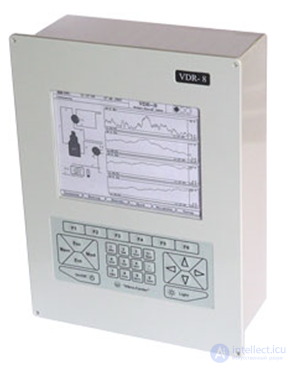
Figure 8.8 – VDR-8 stationary vibration parameter monitoring system |
The standard delivery set of the instrument includes: the Diana-S instrument itself, a vibration sensor with magnetic mount, a power supply unit, and the "Atlant" software.
Vibration monitor - 1PM - a stationary device designed for continuous monitoring of the technical condition of units by indicating vibration signals at levels: "normal", "dangerous", "emergency", as well as automatic emergency shutdown of units in case the vibration level rises to the maximum permissible value. Piezoelectric vibration measuring transducer with integrator, preamplifier, and temperature compensator PVP-3 (Figure 8.7).
VDR-8 stationary vibration parameter monitoring system includes the VDR-8 base instrument and a set of sensors. The VDR-8 (Vibro Data Recorder) belongs to the class of modern electronic vibration signal recorder-analyzers, in which functions of expert vibration diagnostics of equipment condition are additionally implemented (Figure 8.8).
A single instrument comprehensively solves the problem of equipment condition monitoring, since it allows recording vibration, temperature, and process parameters. Based on the results of processing the primary information, the VDR-8 can activate warning and emergency alarms, diagnose developing equipment defects, and plan the timing of repair work.
The expert diagnostic program built into the instrument implements a whole set of methods and tools. These are diagnostics based on vibration signal spectra, power in frequency bands, the envelope spectrum of the vibration signal, signal kurtosis, etc. The number of vibration monitoring channels is 8.
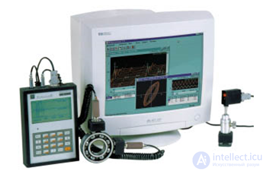
Diagnostic complex based on the SK-2300 vibration analyzer is designed for measuring and analyzing vibration of rotary equipment. The measurement results obtained by the SK-2300 can be analyzed using the vibration analyzer itself, or transmitted to a PC for recording in a database, ensuring further analysis using specialized software. Based on the analysis of the measured data, reports are automatically compiled containing information on the current condition of the monitored equipment, the recommended timing and types of repair of the unit and its individual components, as well as the suspected defects of equipment components (Figure 8.9).
|
Figure 8.9 - Diagnostic complex based on the SK-2300 vibration analyzer
|
Using the vibration analyzer, the time waveform, spectrum, and envelope spectrum of the vibration signal can be measured, including with external synchronization from a photo pickup; the vibration analyzer can have special versions: for operation in explosive zones of classes B1a and B1g with vapor-air mixtures of class IIa, temperature groups T1..T4, as well as a moisture-proof version (IP68). The software is implemented using client-server technology and has the following advantages: MIMOSA standard database (ability to work with other diagnostic programs); a powerful apparatus for graphical display and data analysis; compatibility with Windows 95 and Windows NT operating systems; multi-user access to data (SQL); network support (TCP/IP); 32-bit architecture. The SK-2300 can be supplied with the "Expert" expert system, designed for automated diagnostics of the condition of monitored equipment based on archived data.
|
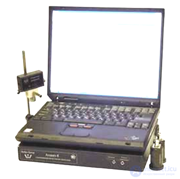
Figure 8.10 – Atlant-8 - multichannel synchronous recorder and analyzer of vibration signals
|
Atlant-8 multichannel synchronous recorder and analyzer of vibration signals. The basis of the Atlant spectrum analyzer is a portable "laptop" type computer, in which the functions of signal registration, processing, and storage are combined. The functions of primary vibration signal processing, filtering, and synchronous digital conversion are implemented in an external unit (Figure 8.10). Vibration sensors and a phase marker used for balancing are connected to this unit. The use of a computer for signal processing removes practically all the limitations inherent in conventional portable vibration monitoring instruments. These are: a small number of input channels, low speed, limited memory capacity. The ability to perform continuous signal recording for tens of seconds or minutes allows such instruments to be used for recording transient processes in equipment, for monitoring vibration processes in low-speed mechanisms, etc. The Atlant instrument includes a set of vibration diagnostics programs. Using the Atlant software, it is possible to analyze the time waveforms and spectra of vibration signals, and wavelet transforms of signals. The Atlant-8M version of the instrument has 16 input channels. Of these, 8 are intended for vibration signals, while the remaining 8 can be used to register signals from any other sensors. The distinguishing feature of the Atlant-8M instrument is that it can operate in stationary monitoring system mode. Sensors are installed on a unit requiring continuous monitoring for a period of time, for example, at startup after repair.
|
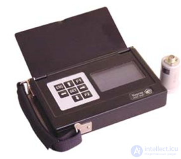
. Figure 8.11 – Korsar+ signal vibration analyzer |
Korsar+ vibrometer with memory, signal analyzer is designed for the rapid solution of vibration diagnostics tasks. First of all, it allows monitoring the overall vibration level (RMS, peak, peak-to-peak) in terms of vibration acceleration, vibration velocity, and vibration displacement. Recorded vibration measurements can be stored in memory (up to 20 thousand measurements) and transmitted via the RS-232 interface to a computer. The instrument can be used to record the shape of vibration signals, vibration spectra in the range of 10 - 1000 Hz, and store vibration signals and spectra in the instrument's memory (up to 400 units). The "Atlant" program is used to store the recorded signals and spectra on a personal computer. An explosion-proof version of the instrument is manufactured for hazardous industries (Figure 8.11).
TOPAZ vibration analyzer - is a portable microprocessor-based vibration measuring instrument that can operate together with the "DIAMANT 2" software as part of an equipment condition monitoring system, and as a standalone vibration analyzer. The instrument makes it possible to measure and analyze dynamic signals with the ability to record them in non-volatile memory, for subsequent viewing and analysis. The instrument's software can be loaded from any personal computer via a standard RS-232 interface.
The "TOPAZ" analyzer is single-channel, but its capabilities can be expanded through the use of 4- or 16-channel multiplexers. In this case, the number of measurement channels can be anywhere from 1 to 16. Special functions are provided for early diagnostics of rolling bearing and gear condition, measurement of crest factor, kurtosis, and envelope spectrum. The balancing program allows dynamic balancing of rotors in their own bearings using up to 16 correction planes and up to 16 measurement points. Functions for vector addition and decomposition, checking the influence coefficient matrix for stability, and calculations using matrix and vector methods are provided.
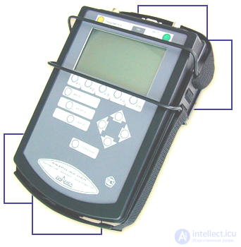
Figure 8.12 - QUARTZ vibration analyzer
|
Figure 8.13 - SK – 100 vibrometer |
The KVARTS vibration analyzer can be used both as an independent vibration analyzer and as a data collector in a technical condition monitoring system. In this case the database is the "DIAMANT 2" software. Using an 8-channel expansion unit together with the "KVARTS" vibration analyzer provides the ability to obtain synchronous time or frequency characteristics of run-up and coast-down of units, as well as spectral cascades simultaneously across eight channels, and with the use of 4- or 16-channel multiplexers the number of measurement channels can be anywhere from 1 to 16. For diagnosing rolling bearings and gear drives, the instrument implements special functions such as envelope spectrum, kurtosis, and crest factor. For measuring and analyzing vibration of low-speed machines, such as hydro-generators, "KVARTS" can be supplied in a low-frequency version, providing a lower frequency limit of 0.3 Hz (figure 8.12).
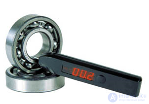
SK-100 vibrometer is designed for assessing the current condition of mechanical equipment by the vibration level of its assemblies: during operation; when returning from repair. The SK-100 is a pocket-sized device, has a small weight, and is capable of operating over a wide range of climatic conditions. The instrument is controlled using a single button. On the front panel of the instrument there is a three-digit digital display, which shows the measured RMS value of vibration velocity, as well as the instrument's operating mode and battery status. The SK-100 allows measuring the root-mean-square (RMS) value of vibration velocity in the frequency band of 10...1000 Hz, in accordance with GOST 25275-82 (figure 8.13).
Insulation diagnostic systems for electric machines. Problems with the stator insulation of high-voltage electric motors, except for emergency mechanical damage, do not arise instantaneously. Insulation breakdown is preceded by a fairly long period of time, during which micro-discharges arise at the site of the future insulation defect, the level of which gradually increases. To promptly detect these discharges and assess the rate of their increase, PD (partial discharge) monitoring instruments are used.
|
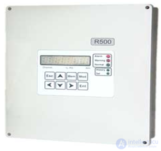
Figure 8.14 - R-500 partial discharge level monitoring instrument |
R-500 instrument for monitoring the insulation condition of energized high-voltage electric motors based on partial discharge level. The multichannel R-500 instrument allows monitoring the insulation condition of electric machines in continuous monitoring mode. The instrument is mounted in the control panel, has small dimensions, and is easily connected to the existing stator winding temperature monitoring circuits (figure 8.14).
|
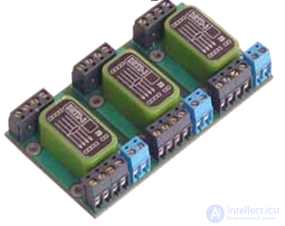
Figure 8.15 - DRTD-3 sensor
|
At set time intervals, the instrument automatically monitors the presence of partial discharges on each channel (up to 15 in total), calculates the intensity of the partial discharges, and compares it with the allowable values stored in memory. When the emergency threshold of partial discharge intensity is exceeded, the R-500 instrument can disconnect the equipment from the network, or transmit information to a higher-level system via the communication channel. When an alarming level of partial discharge intensity is reached, the alarm is activated. The instrument monitors the rate of rise of PD intensity over a period of up to several years, and if the rate of change of the PD level is high, protection is also triggered.
The DRTD-3 sensor is designed to register partial discharges in the stator windings of electric machines. Thermistors embedded in the winding at the manufacturer's factory during the manufacture of the electric machine are used as the PD antenna (figure 8.15).
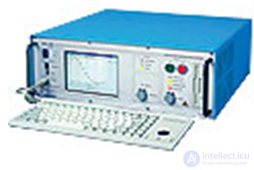
Insulation diagnostic system IDA – 200. Universal portable system for diagnosing electrical insulation under field conditions. Can be used for monitoring the insulation of generators and electric motors. Measures capacitance and dielectric losses (tg α) at discrete frequencies below and above the power-line frequency, from 0.1 mHz to 1 kHz. This allows obtaining a larger volume of information about the condition of the insulating material, including the ability to recognize defects in individual elements and identify aging processes in insulating materials (figure 8.16).
|
Figure 8.16 - IDA – 200 insulation diagnostic system |
Review questions
1 List the main defects of electric machines and their manifestations.
2 What means and methods of monitoring are used to assess the condition of individual assemblies of electric machines?
3 Describe vibration diagnostics of electric machines.
4 List the main defects of electric machines of an electromagnetic nature.
5 What are the most dangerous stator defects that can be determined from vibration parameters?
6 What are the main rotor defects that can be diagnosed from vibration?
7 What are the main defects of stator steel and copper that can be diagnosed from vibration?
8 How is stator eccentricity diagnosed from vibration parameters?
9 How is improper axial alignment of the motor diagnosed from vibration parameters?
10 How is rotor eccentricity diagnosed from vibration parameters?
11 How is broken rotor bars diagnosed from vibration parameters?
12 How are defects of the tooth-slot structure diagnosed from vibration parameters?
13 What functional capabilities of vibration diagnostics can be implemented by modern software?
14 What technical means are used to implement the vibration method of diagnosing electric machines?
15 What are the features of stationary and portable systems for vibration monitoring and diagnostics?
16 What methods and means are used for diagnosing the insulation of electric machines?
продолжение следует...
Часть 1 8. Diagnostics of Electrical Machines

Comments