
Lecture
Power Loss Protection (PLP) for SSDs is not a new concept, but the ways and methods of protecting SSDs during and after a power failure have significantly improved in modern SSD models. The purpose of power loss protection is to accomplish two main tasks:
Note: the SSD mapping table, or Flash Translation Layer (FTL), is responsible for the logical distribution of physical data on the SSD.
Under conditions of a normal system shutdown, the SSD receives a command (Standby Immediate Command) from the host's ATA driver, warning the SSD of the system shutdown so that the SSD can prepare for a power interruption. During a normal system shutdown, the SSD has enough time to transfer data from the cache buffers and update the mapping tables.
High-quality SSDs use a hardware system with power capacitors built into the SSD and/or power loss protection (PLP) in firmware, allowing critical metadata to be written to flash memory to ensure successful SSD recovery upon power-up. Currently, Kingston products use tantalum polymer capacitors to implement the PLP function.
Early SSD models were not as well prepared for sudden power loss as modern ones. Typically, an SSD that experienced a sudden power loss would not respond on the next power cycle. In many such cases, power failures led to SSD failure and data loss.
Hardware PLP – hardware PLP is primarily designed to reduce data loss by maintaining SSD power, thanks to built-in power capacitors (Power Caps), for a time sufficient to write data remaining in the SSD's cache buffer to flash memory and update the mapping tables. The general scheme of a typical hardware PLP case in an SSD looks approximately as follows:
The SSD controller detects a sudden power loss
Firmware PLP – software PLP protection is also designed to reduce the likelihood of data loss thanks to the firmware's ability to restore the mapping table on the next power-up after a failure. The general scheme of a typical firmware PLP protection case looks approximately as follows:
Firmware PLP protection is a highly effective way to prevent data loss in enterprise storage systems. For example, SSDs configured in RAID arrays need to be able to recover and return to a healthy state after a power failure in order to maintain the integrity of the RAID array. One or more failed drives in the array will result in the array shutting down with a high probability of data loss.
In another enterprise system scenario, SSD drives can form a large storage pool in which physical SSDs are divided into multiple LUNs and shared among multiple hosts. In this example, a critical characteristic is high availability, and firmware-based PFAIL protection ensures successful recovery of the SSD serving the LUNs and hosts.
By putting client SSDs into servers, owners create, with their own hands, the conditions for their possible corruption or even loss. Unlike server-grade drives, consumer drives have no power loss protection (PLP).
The purpose of DRAM
Although SSDs are built on non-volatile NAND memory, they contain a volatile buffer (DRAM cache). Upon receiving a write request from the OS, the SSD controller places a portion of the data into this buffer – to improve performance and optimize writes. Until the data reaches the NAND cells, it is at risk – a loss of power to the dynamic memory results in the loss of its contents, and what the OS considers a completed fact – a write to NAND – does not actually happen at all. It would be fine if only a small portion of data were lost. In the absence of end-to-end data integrity checking (for example, on the part of the file system), errors accumulate and lead to data corruption (GIGO – Garbage In, Garbage Out).
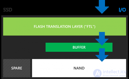
The second purpose of SSD DRAM – caching metadata, address tables in the FTL (Flash Translation Layer). Each new host write request updates the FTL. In addition, addresses change as a result of background controller activity such as garbage collection and wear leveling. For these operations the controller uses DRAM, which has bit-level addressing, lower latency compared to NAND cells, and virtually unlimited rewrite endurance.
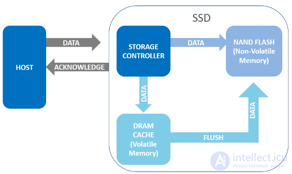
Fig. 1. Upon a normal system shutdown, data is flushed to NAND flash memory, and the SSD signals the host that the drive is ready for power-off.
When the host wants to write data to the SSD, the data is first stored in a temporary buffer (volatile memory), if the SSD has a DRAM cache, before it is flushed to non-volatile flash memory for safe storage; otherwise the data is stored directly in NAND flash memory (non-volatile memory), where it is stored safely even in the event of a power loss.
During a normal system shutdown, the host first warns the SSD that the system is shutting down. The SSD then prepares for power-off, flushes data from volatile storage to non-volatile flash memory, and then signals the host that the drive is ready to be powered off.
This process solves two important tasks: first, it ensures that data is safely stored before power-off; and second, the mapping tables are updated. The mapping tables track logical block addresses in relation to the physical pages of flash memory, indicating where the data is stored on the flash drive.
An unsafe shutdown occurs when power is cut before the shutdown notification is completed. This prevents data from being moved out of the temporary buffers ("flushed") into the non-volatile NAND, which leads to data corruption or loss, or renders the storage device unusable. Examples of unsafe shutdowns include unexpected power outages, accidental removal of the solid-state drive from a computer, disconnecting the storage device while powered on, or loss of battery charge.
Solid-state drives are especially vulnerable to power loss events. Unlike hard disk drives, solid-state drives have no mechanical parts, so every component is electronic. Internal data management on a solid-state drive involves many operations performed in the background, and any power failure can mean an excessive interruption of those operations, which can affect the drive's performance.
Unstable Power
You protected yourself from external power surges with a UPS, but the server's power supply died… Or the I/O controller. Or the motherboard. A client machine going down will not lead to serious consequences. But an enterprise server is a tool of collective work, and data integrity and availability have the highest priority. Higher risks, higher responsibility.
Commercial-grade SSDs have power protection – capacitors: aluminum, tantalum, ceramic, etc. Their residual charge provides a temporary window sufficient to flush data from the buffer into NAND and update the addressing tables.
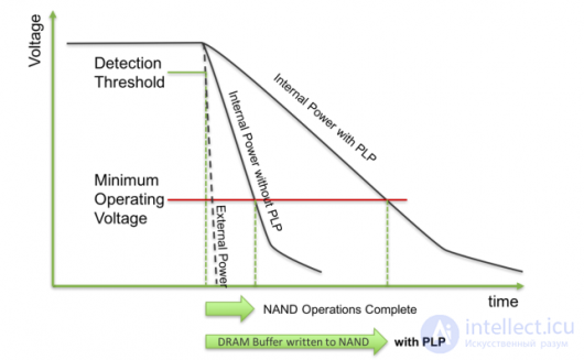
PLP pursues two goals:
Due to the high cost of capacitors and the price sensitivity of the client SSD market, hardware PLP protection is not installed on them. At best, a software half-measure is applied: metadata logging at the FTL and file system level. If this is implemented in SSD firmware, when new data is written, tags (spare bytes) are written to a separate log file, including the logical block addresses (LBA), error correction codes (ECC), and other structural information. After a system restart and log verification, the original address tables are restored. (Data in the buffer at the time of the incident is lost in any case.)
In the world of PCs, data loss is not as critical – due to its comparatively low value. In addition, many modern file systems already use journaling. The sources of risk are not new either – a cache buffer (DRAM cache) is present in any HDD, and it is usually not disabled. Enterprise and data center servers and storage systems are a completely different matter. Even a small probability of loss must be taken into account – data and reputation are worth more.
What if you disable the cache?
The cache buffer speeds up the processing of host I/O requests and is used to prepare clean pages for writing – reducing wear on the SSD cells.
Enable the cache on an SSD without PLP – and you risk losing data. Disable it – and you lose performance and shorten the SSD's lifespan. Without a buffer in dynamic memory, an SSD's operation will be sluggish, and its life short. In Write Through mode, consumer drives do not outperform HDDs:
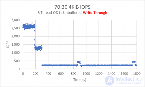
«Oh, how inconvenient this turned out to be».
How to determine whether an SSD has PLP?
Read the documentation. SSD manufacturers state directly what type of application their products are intended for. Tempted by a low price and saving the user's money (did he ask you to?), you put him at risk without his consent
Microcontrollers: providing next-generation power loss protection
Power loss protection (PLP) mechanisms are available on most solid-state drives, especially those designed for high-performance applications. Such industrial-grade storage devices are typically widely used in harsh conditions, operate around the clock, and require uncompromising device integrity.
Typical PLP solutions include the use of batteries and supercapacitors, which provide a power hold-up delay, allowing controller and flash functions to be completed in the event of a power failure.
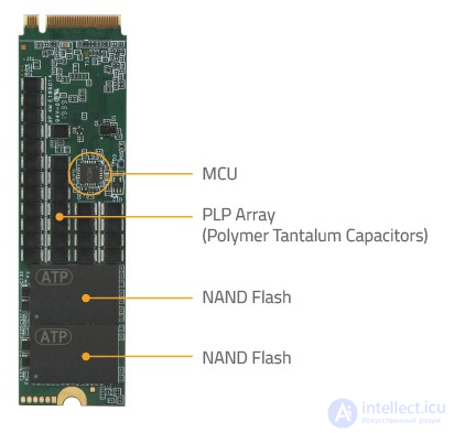
ATP Electronics, one of the first companies to develop and release smaller form-factor solid-state drives, such as the M.2 2242 with a built-in PLP array, is taking things a step further by using a microcontroller (MCU) that provides unprecedented protection for the next-generation serial port. ATA and NVMe solid-state drives for the industry's best PLP protection.
How MCUs improve the PLP mechanism
Integrated into the ATP PowerProtector 4, the brand-new PLP array design uses a new power management IC (PMIC) and a new microcontroller with firmware that allow the PLP array to work intelligently across various temperatures, power failures, and power states.
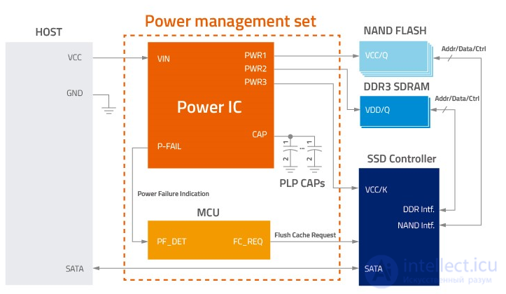
Fig. 1. New PLP array from ATP with PMIC and a microcontroller programmable via firmware.
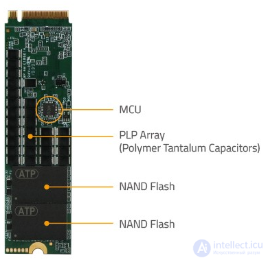
Fig. 2. MCU-based design implemented in the latest ATP NVMe SSD.
Features and Benefits
The next-generation ATP SSDs have a switch between the external input voltage and the internal SSD circuitry. This switch is controlled by the MCU. Since the input voltage is monitored by the microcontroller in real time, it protects the SSD by sending a signal to the protective switch to disconnect the input voltage as soon as it is detected to exceed the specified maximum tolerance.
The MCU helps eliminate noise glitches using an evaluation mechanism that determines when power drops below a certain value, thereby correctly identifying power loss versus simple power instability. Without the MCU, power instability could be mistakenly interpreted as a power failure and thus falsely trigger a cache flush, potentially leading to the SSD "hanging" or freezing.
Table 1. SSD power on/off with / without MCU
|
SSD without MCU |
SSD with MCU |
|
PLP capacitors need to be discharged / reset before power-on |
Immediate power-on is initiated regardless of the residual voltage on the PLP capacitors |
|
If the power-off state is very short:
|
If the power-off state is very short:
|
Thanks to MCU-based PLP, fast power on/off can be guaranteed without the potential risk of drives going undetected due to improper controller reset.
Polymer tantalum capacitors are essential elements of ATP's PLP technology. By providing backup power, they ensure that data from the DRAM cache will be flushed to NAND flash for safe storage, and the last write command will be completed when a power loss event occurs.
Overcharging can damage the capacitors and thereby compromise their protective function. The MCU monitors the capacitor voltage in real time and disables charging as soon as it detects that the voltage is too high. This ensures that the PLP capacity is sufficient to complete the cache flush during a power failure. It also prevents premature aging of the PLP capacitors.
Summary and Conclusion
The ATP PowerProtector 4 combines an MCU-based design to provide advanced power management and PLP capabilities for next-generation ATP SATA and NVMe SSDs. By combining hardware and firmware solutions, the MCU-based design protects the data as well as the storage device, providing a higher level of integrity and reliability. Depending on customer request, advanced features can be customized, allowing PLP capabilities to be tailored to the unique requirements, needs of a specific application, or use cases.
The following table lists the benefits of each feature.
Table 2. Summary table showing how each MCU feature and benefit provides advanced PLP capabilities for the latest ATP SSDs and modules.
|
Improved drive protection |
|
|
Better data integrity |
|
|
Fast power on / off |
|
|
Precise control of power on / off sequences |
|
|
Customization options |
|
Next-generation ATP SSDs with the new MCU-based design include mSATA, 2.5-inch SSDs, M.2 2242/2280 modules, and NVMe. Available with I-Temp and C-Temp support, the SSDs also feature RAID mechanism support and end-to-end data path protection. ATP's solutions, designed exclusively for industrial use, undergo rigorous testing and validation to meet the high reliability, performance, and durability requirements of mission-critical applications, ensuring the best total cost of ownership (TCO). For more information about ATP's MCU-based industrial flash drives, visit the ATP website or contact an ATP representative .

Comments