
Lecture
Properties of insulating materials. Dielectric materials serve as insulation for the current-carrying parts of switching devices. They include such diverse types of electrical insulation as vacuum, SF6 gas, air, petroleum and synthetic oils, and solid dielectrics. At the same time, the physical conditions in which the insulation must exist and function impose certain requirements on the physicochemical parameters of the material, limiting the possible kind and type of electrical engineering materials used. Here it is necessary to take into account various characteristics of the material:
Real dielectrics differ from ideal ones, primarily by the presence of micropores in the body of the dielectric, especially at the “electrode-dielectric” interface. They arise during the manufacturing process of the electrical insulation structure, although in some cases they may also form during operation, for example as a result of vibration or mechanical stresses. The presence of pores and, associated with them, the occurrence of ionization phenomena, is one of the main factors in the deterioration of the properties of electrical insulation during operation – aging of dielectrics.
Aging of a dielectric (its gradual change, accompanied by deterioration or complete loss of insulating properties) is caused by processes associated with chemical, thermal, mechanical and electrical influences. These processes act simultaneously and are interrelated. The chemical processes of deterioration of organic insulating materials include oxidation and reactions with aggressive components of the environment, which are favored by the presence of moisture and elevated temperature. When heated, due to external causes and dielectric losses, wear of the material is accompanied by decomposition of the substance, the appearance of brittleness, and a decrease in electrical strength. The main aging phenomena also include physical and chemical changes in organic insulating materials caused by partial discharge processes. Mechanical influences, causing disruption of material integrity (tears, delamination), reduce the electrical strength of the insulation structure.
All solid dielectric materials can be divided into groups using different principles. For example, they can be divided into inorganic and organic materials. Inorganic dielectrics: glasses, mica, ceramics, inorganic films (oxides, nitrides, fluorides), metal phosphates, electrical insulating concrete. Features of inorganic dielectrics - non-flammable (as a rule), light-, ozone- and heat-resistant, have a complex manufacturing technology. Aging under AC voltage is practically absent, but they are prone to aging under DC voltage. Organic dielectrics: polymers, waxes, varnishes, rubbers, papers, varnished cloth. Features of organic dielectrics - flammable (mostly), low resistance to atmospheric and operational influences, have (mostly) a simple manufacturing technology, and as a rule are cheaper compared to inorganic dielectrics. Aging under DC voltage is practically absent; under AC voltage they age due to partial discharges, dendrites and water treeing.
The most common liquid dielectric in power engineering is transformer oil. Transformer oil is a refined petroleum fraction obtained by distillation, boiling at a temperature of 300 °C to 400 °C. Depending on origin, crude oils have different properties, and these distinctive properties of the source material are reflected in the properties of the oil. It has a complex hydrocarbon composition with an average molecular weight of 220 - 340 a.m.u.
Insulating oil is also a heat-conducting and protective medium. During aging, the oil oxidizes, which leads to the formation of organic acids, either soluble in the oil or forming deposits (sludge). Moistening reduces its electrical strength. Thermal effects lead to cracking. Aging of the oil reduces the reliability of the insulation structure, since increased acidity promotes aging of the solid insulation, and sludge deposition increases dielectric losses and impairs heat dissipation. Moisture from the oil, passing into the solid dielectric, intensifies destructive processes in it. The presence of gas bubbles in the oil promotes the development of partial discharges. The final result of the influence of these factors on the insulation structure is a change in the structure of the dielectrics, their properties, and the appearance of internal defects and decomposition products.
Direct methods for determining the intensity of the listed processes, suitable for operating conditions, do not exist. Indirect monitoring methods are used. For this purpose, insulation parameters are used, whose values are determined by processes occurring in the dielectrics (polarization, absorption, ionization, conductivity, etc.). Such parameters include the complex conductivity of insulation, dielectric losses, capacitance, and partial discharge intensity. The dependencies of these parameters on temperature, applied voltage, time, etc. are also used for diagnostics.
Among gaseous dielectrics, the most widely used is SF6 gas - sulfur hexafluoride SF6. It gets its name from the abbreviation for “electric gas” (elegas). Electrical strength at atmospheric pressure and a gap of 1 cm is E = 89 kV/cm. The molecular weight is 146; characteristic features are a very large coefficient of thermal expansion and high density. This is important for power installations in which cooling of some parts of the device is carried out, since with a large coefficient of thermal expansion a convective flow that carries away heat is easily formed. SF6 gas is chemically inert, non-toxic, non-flammable, heat-resistant (up to 800 °C), explosion-proof, decomposes weakly in discharges, and has a low liquefaction temperature. In the absence of impurities, SF6 gas is completely harmless to humans. However, the decomposition products of SF6 gas resulting from the action of discharges (for example, in a spark gap or circuit breaker) are toxic and chemically active. The set of properties of SF6 gas has ensured a fairly wide use of SF6 gas insulation. In devices, SF6 gas is usually used under a pressure of several atmospheres for greater compactness of power installations, since electrical strength increases with increasing pressure.
Currently, for the 6 - 10 kV voltage class, mainly vacuum circuit breakers (VCBs) are produced, whose wide application is caused by their moderate cost and high operational qualities, above all, high switching and mechanical durability, high reliability and low operating costs. The main advantages of VCBs are due to the arc-quenching properties of vacuum, its high electrical strength (of the order of 30 kV/mm) and the principle of arc quenching in vacuum, which, with a contact gap of 6 - 8 mm, ensure that 10 kV circuit breakers comply with the requirements of GOST 687. AC arc quenching is carried out when the contacts are separated in a vacuum of about 10 – 6 mm Hg. Since the electrical strength of the vacuum gap is quite high, disconnection is guaranteed to occur at gaps greater than 1mm, with the arc burning time being minimal in this case.
Methods for measuring diagnostic parameters of insulating materials. Measurement of dielectric losses and insulation capacitance. Bridge and non-equilibrium compensation methods are used.
Diagnostic parameters:
- when testing de-energized equipment – dielectric loss tangent (tan δ) and insulation capacitance;
- when monitoring equipment without taking it out of service – change in complex conductivity, tan δ and insulation capacitance.
The bridge method is based on comparing the parameters of the monitored object with the parameters of a circuit element accepted as a reference.
When measuring tan δ and the capacitance of insulation of de-energized equipment, a capacitor with negligibly small dielectric losses is used as the reference.
When monitoring equipment under operating voltage, a reference capacitor, fed from the voltage transformer of the busbar system to which the monitored object is connected, is used in the comparison branch. A scheme for comparing the parameters of two similar objects, one of which is taken as the reference, is also used.
Due to the presence of phase shifts in the comparison branches of monitoring circuits under operating voltage, the measured value of tan δ will differ from the actual value. The error is eliminated by taking the change in tan δ over time as the diagnostic parameter. In the scheme for comparing the parameters of two objects, the difference Δ tan δ = tan (δx – δ0) ≈ tan δx – tan δ0 is determined.
When monitoring a de-energized object at its installation site, it is necessary to exclude from the measurement results the error from influence currents caused by the operating voltage on the busbars and other objects of the switchgear. For this, two measurements are carried out, with the second one being taken with the bridge voltage phase shifted by 180°. The result is determined by the formulas:

where  – results of the first measurement;
  – results of the second measurement.
The non-equilibrium compensation method is based on measuring the sum of the three-phase system of currents flowing through the insulation of the three phases of the monitored object under the action of the operating voltage. When the phase currents are equal, the total current will be zero. When the complex conductivity of the insulation of one of the phases increases, the current through it increases and the total current changes accordingly. Due to the low probability of a simultaneous and identical change in the dielectric characteristics of all three phases of the object, the method makes it possible to detect a change in the state of the insulation of any of the phases. Relative change in current  – respectively, the current through the insulation and the complex conductivity of a defect-free object; ΔI and ΔY – changes in current and conductivity, determined by defects.
When separately measuring the active and reactive components of the vector ΔI:

(it is assumed that Δ tan δ < 1).
When measuring the current modulus ΔI

For operational purposes, it is sufficient to measure the current modulus. To determine the phase of the object and the nature of the defect, a vector meter is used. The setpoint of the alarm signal device is selected based on the maximum permissible value of the monitored parameter.
Insulation resistance measurement. The measurement circuit consists of a series-connected monitored insulation section, a voltage source, and a device measuring the current through the insulation. Diagnostic parameter – insulation resistance.
The measuring device – a megohmmeter, contains a DC voltage source U 0 and a voltmeter V, at the input of which a reference resistor R 0 is connected. The measured resistance R x = R 0 ((U / U 0) – 1) ≈ R 0 (U / U 0), since the value of U 0 compared to U can usually be neglected. The measurement limits depend on the resistance of the resistor R 0. The main source of measurement error is current flowing over the surface of the insulation structure and through other elements not subject to inspection. To eliminate surface currents, shielding is applied – supplying a potential equal to the potential of the reference resistor to an electrode installed along the path of these currents. The shielding capability is limited by the resistance value R E of the part of the equipment located between the R x and E terminals of the megohmmeter, which shunts the reference resistor. The error introduced by this resistance
Δ R x / R x = R 0 /R E.
Measurement of absorption characteristics. When a DC voltage is applied to an insulation structure, a short-duration geometric capacitance charging current pulse occurs, along with a slowly decaying absorption capacitance charging current and a steady-state current determined by conductivity. Measuring the current through the insulation or the accumulated charge at specific points in time provides information about the degree of its non-uniformity. The insulation resistance measurement is determined from megohmmeter readings taken 15 and 60 s after voltage is applied to the object. The diagnostic parameter is the absorption coefficient K a = R 60 / R 15.
The absorption capacitance of the insulation is determined during charge and discharge cycles of the object. The diagnostic parameter is the ratio of absorption capacitance to geometric capacitance. The values ΔC / C50 and (C2 – C50) / C50 are determined, where ΔC – absorption capacitance; C50 – geometric capacitance (corresponds to the value measured at 50 Hz); C2 – part of the absorption capacitance (corresponds to the value measured at 2 Hz).
Dispersion is determined by charging the object's capacitance with a rectangular voltage pulse U 0 of 3 ms duration and measuring U B across it after 300 ms, when the introduced charge has been distributed between the geometric and absorption capacitances of the insulation. The diagnostic parameter D = UB / (U0 - UB).
Measurement of partial discharge (PD) characteristics. Measuring partial discharge (PD) signals is one of the most promising methods for monitoring the condition of high-voltage insulation, and it should be implemented as widely as possible in practice. In all high-voltage laboratories worldwide, PD measurement during testing of high-voltage equipment is the primary method of insulation condition monitoring. However, for monitoring equipment under operating conditions, PD measurement is still applied relatively rarely. Problems in measuring PD under real operating conditions are related to various types of interference at operating substations. The most widely used are electrical and acoustic methods of PD measurement. The main diagnostic parameter for operational monitoring is the apparent charge of the partial discharge.
Electrical methods provide determination of the value of the monitored parameter. Acoustic methods are used to detect the presence of discharges and locate their source.
Monitoring of electrical insulating oil. The physico-chemical characteristics of the oil determine the performance of the insulation structure and serve as diagnostic parameters. The main characteristics of electrical insulating oil and the methods for determining them: breakdown voltage and tg δ (GOST 6581), acid number (GOST 5985), flash point (GOST 6356), mechanical impurity content (GOST 6370), moisture content (GOST 7822), and gas content (gas extraction in an evacuated vessel).
The processes of thermal decomposition of insulation and its destruction by electrical discharges lead to the release of gases that dissolve in the oil. Each type of defect corresponds to a characteristic set of gases. Diagnosing insulation based on gas content in oil consists of determining the type of defect (qualitative monitoring) and assessing the degree of its development (quantitative monitoring). Sources of information are the composition of dissolved gases, their concentration, and the rate of its change. Analysis of gases dissolved in oil can be performed by any method that provides the required sensitivity. Gas chromatography has become the most widely used method.
A feature of electrical equipment monitoring is the need for preliminary extraction of gas from the oil sample. The collected oil sample is placed in a sealed vessel whose capacity exceeds the volume of the oil. After the equilibrium gas concentration is established, a gas sample is extracted from the space above the oil for analysis. Acceleration of gas exchange is achieved by raising the temperature to 60 – 100 °C and increasing the contact area between the oil and the gas medium in the vessel (bubbling of carrier gas or air through the oil from the vessel; preliminary evacuation of the vessel volume).
Determining the composition of metal compounds present in the oil can provide additional information about the nature of the defect.
Thermal imaging diagnostics can effectively detect decomposition of paper-oil insulation of high-voltage equipment windings:
To assess the condition of contacts and contact connections of oil, SF6, and vacuum circuit breakers, standard tests are performed, including tests requiring the use of special measuring instruments and systems:
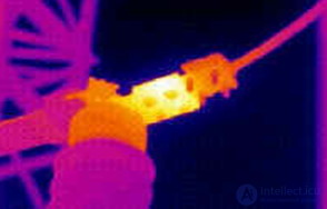
Figure 4.1 – Temperature rise due to poor contact at the circuit breaker bushing
Thermal imagers make it possible to visualize the thermal radiation of objects, measure temperature, and record thermograms on computer media, which enables image analysis and generation of inspection reports. The world leader in the production of thermal imaging equipment is NEC (Japan); a series of GUIDE thermal imagers based on uncooled microbolometer matrix detectors (France) has begun production; among domestic thermal imagers, the IRTIS-2000 computer thermograph is the most popular in the electric power industry. Figures 4.1 and 4.2 show thermograms illustrating local temperature rise due to increased resistance of contact connections.
Point temperature meters – pyrometers, which perform the same tasks as thermal imagers, are widely used for monitoring contact connections. The difference is that working with pyrometers is more labor-intensive and takes longer. At the same time, a large
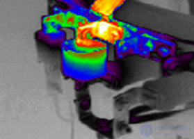
Figure 4.2 – Temperature rise due to poor contact of a bolted connection
number of standard, routine tasks can be solved with these instruments.
Thermographic monitoring of the condition of contact connections of equipment terminals, current-collecting devices, module connections, and circuit breaker arc-extinguishing chamber contacts makes it possible to identify the location of a defect and assess the nature of its development. In most air circuit breaker designs, the arc-extinguishing contacts are located in porcelain housings connected by a metal flange. When the contacts heat up, the temperature rise occurs at the nearest flanges.
Characteristic defects of disconnectors are defects of the contact system and support-post insulators. As shown by the results of thermographic surveys, the most common causes of excessive heating of contact system elements are oxidation of contact surfaces and weakening of the compression springs. Defects of this kind are found during inspection of practically all objects. In addition, common defects include contamination and cracks in the porcelain columns of support-post insulators.
|
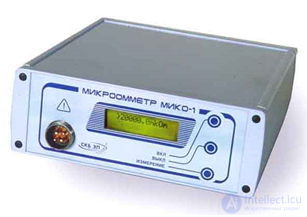
Figure 4.3 - Industrial micro-ohmmeter MIKO-1
|
Excessive temperature at contacts is the main share of faults detected during inspection of switching devices. Overheating occurs due to high active resistance of the contact connection. Most often, defects are found at the jaw-blade contact and disconnector-busbar contact of disconnectors and isolating switches of all voltage classes, at the connections of busbars with current-carrying bushing terminals of oil circuit breakers and power transformers, and at connections with HF traps. Diagnosing poor contact connections usually presents no particular difficulty.
|
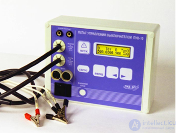
Figure 4.4 – Circuit breaker control panel PUV - 10 |
Industrial micro-ohmmeter MIKO-1 is designed for measuring the contact resistance of contacts, including contacts and contact groups of high-voltage circuit breakers (Figure 4.3). It is specially designed for operation under conditions of powerful power-frequency interference and provides effective suppression of it. Resistance measurement is performed using a 4-terminal scheme.
The instrument's microprocessor, together with other measuring units, provides self-test for serviceability, zero correction and auto-calibration, automatic measurement range selection, elimination of the influence of thermo-EMF in the contacts, digital filtering of interference, and calculation of the measured resistance value.
Range of measured resistances 0 – 0.20000 μΩ.
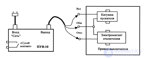
Circuit breaker control panel PUV-10 is designed to control the closing of oil, SF6, and vacuum circuit breakers by automatically sending command pulses to the electromagnet coils (Figure 4.4). The connection diagram of the PUV-10 to the circuit breaker drive is shown in Figure 4.5. The control panel is used together with the PKV/M6 high-voltage circuit breaker monitoring instrument when testing circuit breakers.
Main parameters of the PUV-10 control panel:
- maximum load current - 10 A;
- voltage and current through the "dry contact"- 240 V and 10 A;
- time interval setting resolution - 10 ms;
|
Figure 4.5 - Connection diagram of the PUV-10 to the circuit breaker drive |
- programming range for opening/closing time - 10/990 ms.
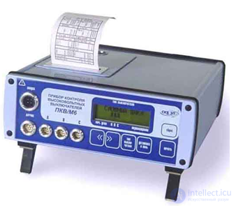
Circuit breaker monitoring instrument PKV/M6 is designed for non-disassembly monitoring of oil, vacuum, and SF6 circuit breakers of all types and voltage classes having from one to three breaks per pole (Figure 4.6). Time characteristics are monitored either simultaneously across all three poles, each having one break, or sequentially for each pole, but with three breaks per pole. Travel characteristics and speed characteristics are monitored using angular (DP21) or linear (DP12) displacement sensors, mounted respectively on the shaft or on the traverse holder of the circuit breaker.
The following characteristics are measured:
- time-related (own switching-on/off time of each pole, total travel time of the crossbar, time asynchrony between poles, contact bounce time);
- speed-related (speed at the moment of switching on/off, maximum speed) in the range of 0.002 - 20 m/s for oil and SF6 circuit breakers;
|
Figure 4.6 - PKV/M6 high-voltage circuit breaker monitoring device |
- travel characteristics (full stroke, stroke to switching-on/off points, overtravel, travel asynchrony of switching, contact bounce travel, rebound, overrun) in the range of 0 - 900 mm with a resolution of 0.5 mm for oil and SF6 circuit breakers.
|
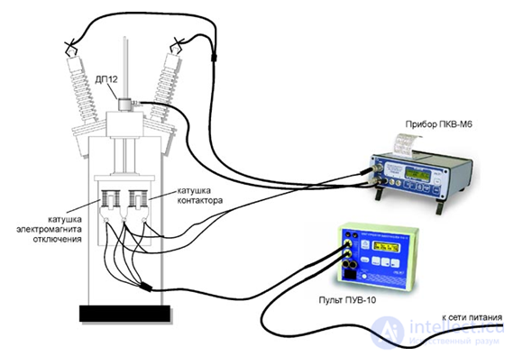
Figure 4.7 - Connection diagram of PKV/M6 and PUV-10 devices
|
The PKV/M6 automatically recognizes the type of complex cycle and measures the characteristics of both the cycle as a whole and its constituent simple operations. In addition, in complex cycles the device determines the duration of command pulses, which allows checking the correct operation of the breaker's interlock contacts. Figure 4.7 shows the method of connecting the PKV/M6 device and the PUV-10 control unit to an oil circuit breaker when monitoring simple operations. To perform monitoring in complex cycles, it is sufficient to disconnect the displacement sensor cable from the device and set the required cycle on the control unit.
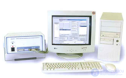
PKV/U1 circuit breaker monitoring device with expandable functions is used for conducting service-life tests of high-voltage circuit breakers (Figure 4.8). The distinctive feature of the device is its reconfigurable structure, comprising two main parts: a permanent core and a variable periphery. The core consists of a computer, a monitor, and a measuring unit with power supply, data acquisition, and computer communication sub-units. The periphery consists of a sufficient number of necessary sub-units and their modifications, differing in number of channels, speed, accuracy, etc., which provide informational connection between the circuit breaker and the device's core.
The PKV/U1 can be configured for any type of circuit breaker: air, oil, vacuum, and SF6 breakers with various numbers of breaks per pole, including shunting resistors and rheostatic sensors of the nozzle drive. The ability to connect several displacement sensors simultaneously (contact and non-contact) makes it possible to study the breaker's kinematic scheme (transfer characteristic and play/backlash) and obtain speed characteristics. Vibration and acceleration sensors installed at various points can provide important information about the magnitude and direction of mechanical loads in various components, while pressure sensors provide the dynamics of air or oil pressure changes in various parts of the breaker.
|
Figure 4.8 - PKV/U1 circuit breaker monitoring device
|
The computer has service software (SW) installed, running under the Windows 95/98 operating system, which controls all operation of the device. The device's software consists of the following main software modules: a measurement control module, an archiving module, a conversion and calculation module, a measurement result display module, and a report generation module.
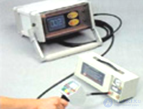
|
Figure 4.9 - Device for monitoring SF6 circuit breakers
|
The device can operate in static and dynamic measurement modes. The static measurement mode can be used to check the correctness of the device's connection to the circuit breaker or to monitor parameters requiring static monitoring. In addition, due to the presence of analog channels, in this mode the device can be used as a multimeter. The dynamic measurement mode is used to monitor circuit breaker parameters during switching-on, switching-off operations, and complex cycles. To determine all monitored parameters characterizing an operation or cycle, a single measurement during that operation or cycle is sufficient.
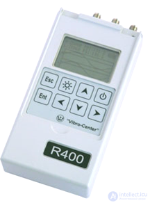
|
Figure 4.10 – Partial discharge monitoring device for insulation
|
GAS CHECK SF6 device for monitoring SF6 circuit breakers is designed for localizing leak locations in SF6 circuit breakers and measuring leak volume by the method of negative ion registration (Figure 4.10). The main advantage of this device is the absence of a radioactive source and the associated problems of registration, storage, and transportation. The device has a memory unit and also outputs data to a printer. The negative ion registration sensor was developed specifically for this application. The high sensitivity of the device does not lead to its damage in the case of large leaks; readjustment from high to low concentrations occurs almost instantaneously, which is due to the ability to automatically switch off and on under the specified circumstances. Sensitivity 10 -7 ml/sec, 1 ppm, 0.2 g/year.
R-400 partial discharge monitoring device for insulation. The R-400 measuring instrument is a compact device for periodic monitoring of high-voltage insulation condition by partial discharges under operating conditions (Figure 4.10). It is designed for registering PD using capacitive, inductive, or transformer sensors. Structurally, the device is designed for use under field measurement conditions.
Vektor – 2.0 M insulation parameter meter is an AC bridge that performs synchronous measurement of electrical signals. The insulation parameter meter is designed for use in monitoring the insulation characteristics of electrical equipment under operating voltage. The device directly measures with high accuracy two voltage drops across two low-resistance resistors, as well as the phase shift angle between the electrical signals on the reference and measured channels. All other parameters are determined by calculation using a microprocessor built into the device housing. The device allows measuring insulation parameters – capacitance and dielectric loss tangent, voltage on the object, frequency, phase shift, power and power factor, impedance and vectors.
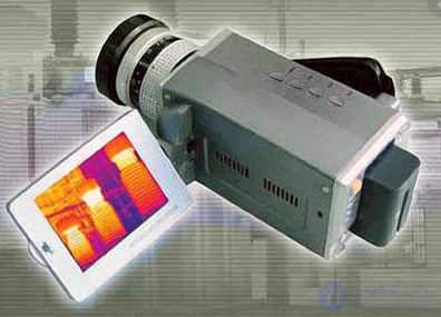
|
Figure 4.11 - IR913+ thermal imager |
IR913 thermal imager – a universal measuring camera with the ability to record information and subsequently process it on a personal computer (Figure 4.11). Provides monitoring and detection of equipment defects in the power industry. The IR913 thermal imager is a microbolometric infrared camera. Main technical characteristics of the thermal imager:
Portable infrared pyrometers. "Kelvin" infrared thermometer is designed for remote non-contact measurement of the surface temperature of various materials based on their own thermal radiation (Figure 4.12). It allows monitoring the temperature of local zones on the surface of hard-to-reach objects and items under high electrical voltage. For power industry enterprises, heating networks, and utilities, the “KELVIN – 400 LTsM” model is recommended
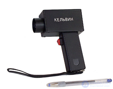
|
Figure 4.12 - "Kelvin" infrared thermometer |
Depending on the modification, the "Kelvin" infrared thermometer can be equipped with a different type of sighting device: a sighting bar – "Kelvin B", an optical sight – "Kelvin P", a laser target designator – "Kelvin LTs". Depending on the optical system used in the device, it may have a different sighting ratio (the ratio of the distance to the object to the diameter of the temperature measurement zone on the object's surface at the point of minimum field of view).
Standard ranges of measured temperatures, °C:
–30…+200; –30…+400; –20...+600; +200…+1300; +500…+1500; +700…+1800; +800…+2200; –30…+1300; –20…+1600; –20…+1800.
Temperature resolution: 1 °C;
Sighting ratios: 90, 120, 150, 180, 200, 250, 300;
for high temperatures (+500…+1500 °C; +700…+1800 °C and above): 400;
for temperatures -30…+200 °C with a resolution of 0.1 °C: 80.
The sighting ratio is determined as follows: the distance to the object (in mm) at which measurements are expected to be taken most often is divided by the diameter of the device's field of view (in mm), which must be at least half the size of the object under study. The resulting value is rounded up to the nearest higher standard value of the sighting ratio.
Information on the diagnostic technical means was taken from advertising brochures and advertisements on the Internet of the manufacturers of this equipment.
1 A change in which main parameters accompanies the aging of dielectrics?
2 Name the methods for measuring diagnostic parameters of insulating materials.
3 What is a partial discharge?
4 What methods are used to measure the characteristics of partial discharges (PD)?
5 Name the main characteristics of electrical insulating oil and the methods for determining them.
6 Explain the operating principle of a thermal imager.
7 What is meant by the sensitivity of a thermal imager?
8 What instruments are used to measure the contact resistance of contacts?
9 Name the functions performed and the main technical characteristics of the PKV/M6 circuit breaker monitoring device.
10 Describe the structure and functions performed by the PKV/U1 circuit breaker monitoring device.
11 Purpose and operating principle of the PKSN-1 device?
12 What is SF6 gas?
13 Purpose and operating principle of the SF6 circuit breaker monitoring device?
14 What is called the sighting ratio of portable infrared pyrometers?

Comments