
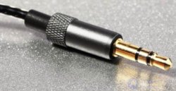
 Best of health and good mood to everyone! Here I have collected pinout diagrams and instructions on how to solder a plug to headphones of all types known to me. I provide instructions on how to repair headphones by yourself and how to connect wires without an electric soldering iron. It will be interesting.
I'll start, perhaps, by listing the known types of audio plugs.
Standard plugs
According to Wikipedia, the following types of jacks exist:
- TS/TRS with a diameter of 6.3 mm (for microphones, electric guitars, mixing consoles, old professional headphones, etc.)
- TS/TRS/TRRS with a diameter of 3.5 mm (the most common, used for modern headphones, microphones, speakers, camera flashes, etc.)
- TS/TRS/TRRS with a diameter of 2.5 mm (for mobile phone headsets, webcams, flashes, etc.)
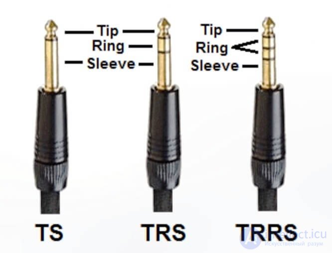
There is also a TRRRS connector type, which is used to transmit not only audio but also video signal.
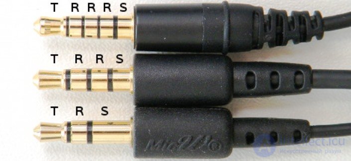
By the way, the designation is adopted according to the principle: T — Tip, R — Ring, S — Sleeve.
How to correctly solder a new plug to headphones while observing the wire pinout
To correctly solder a headphone or headset plug, you need to know the pinout. It is shown in the table below and taken from a website about connectors.
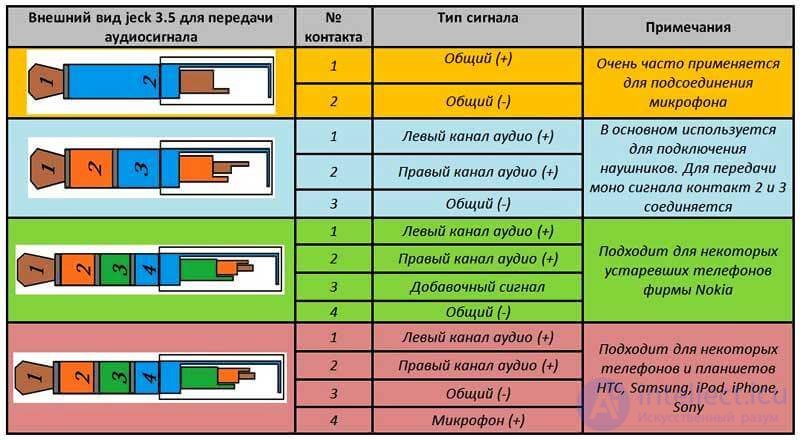
Mini-jacks for speakers and microphones also have such 2-contact and 3-contact plug pinouts.
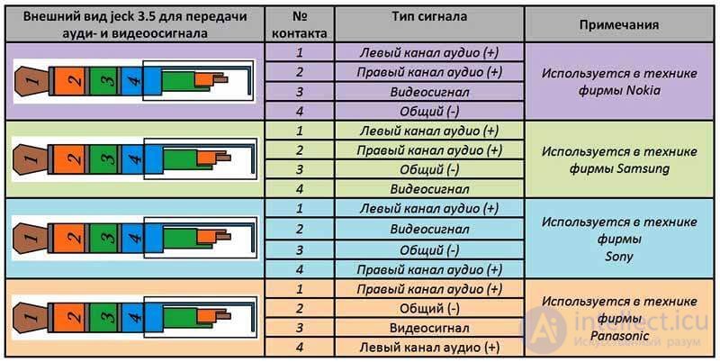
Plugs and their pinouts for more specialized devices (video cameras, headsets) by manufacturer (Nokia, Samsung, Sony, Panasonic) are shown in the following table.
How a three-contact jack is designed
A regular three-contact stereo jack has a coaxial-type construction. Each contact is located in a dielectric sleeve (bushing) and is placed inside another sleeve.
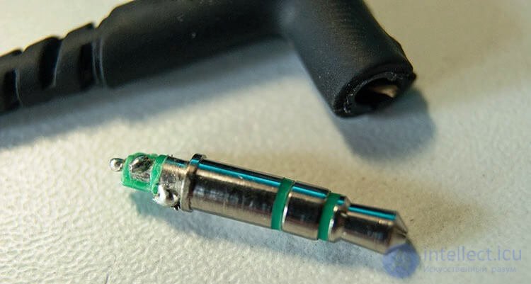
The plug's contacts are separated from each other by plastic sleeves. This plastic is sensitive to overheating, it starts to melt and the contacts will become loose. So if you want to solder a plug for headphones, remember about overheating the contacts with the soldering iron.
Best tubular solder Kaina
How to repair a headphone plug yourself
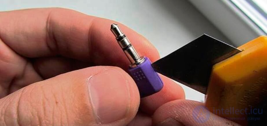
To repair a headphone or headset plug by yourself, you need to carefully remove it from the housing, if it hasn't already come loose on its own. The plug is usually cast in rubber. When disassembling, cut this housing along the seam with a sharp knife. The neater the cut turns out, the easier it will be to restore the housing after repair.
Determining the cause of a headphone fault
A headphone fault most often consists of a break in one of the wires in the plug. Less often a break occurs near the speaker contacts, or the wire breaks due to damage to the insulation.
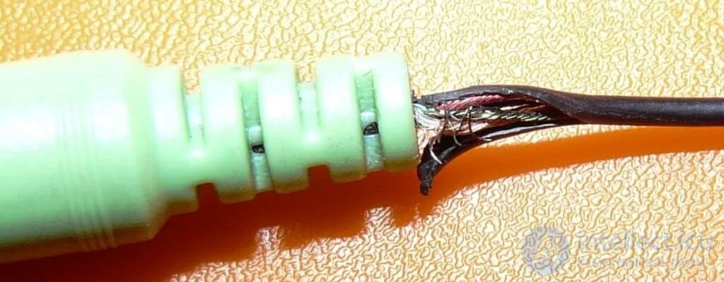
To determine the fault, you need to use a multimeter and test the plug's contacts for continuity. From the diagrams above we already know where the common wire and the left and right audio channels are. If the resistance between the contact of one channel and the common wire is greater than 20 — 120 Ohms, then there is most likely a break or a fracture in the wire. Remember that the typical winding resistance of modern earbud headphones is 32 Ohms.
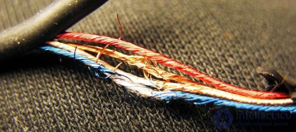
A wire fracture is identified by jumping multimeter readings when the wire is bent.
A break is easiest to find near the headphone speakers. Often the speaker housing is easier to open than the rubber-cast plug is to cut. If the wires are soldered well to the speakers, then you should suspect faults in the plug.
Fixing faults yourself
As soon as you manage to locate the fault, you need to get to it and see it with your own eyes. Then it will become clear exactly how to solder the plug or the headphones.
Suppose the wire break occurred inside the headphone plug. How to disassemble a molded mini-jack is shown above. Ideally, you should record or photograph the wire soldering layout and redo the connector's soldering. Remember that flexible multi-strand wires are coated with a good varnish and are not easy to tin as they are. First you need to burn off the varnish, for example with a soldering iron, a lighter, or a mini torch. After that you can tin the wires with rosin or another flux.
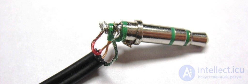
It is better to leave 2 — 3 mm of exposed wire without braid, to increase the strength of the assembly. When you put the plug housing back in place or cast a new housing with sealant, you need to create as large a contact area as possible between the braid and the outer sleeve of the plug. This way, during tugging, the load will be transferred to the most massive part of the plug, and not to the weak contacts of the left and right channels.
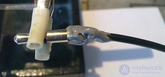
After you have soldered the headphone plug, its internal contacts can be filled with hot melt glue, epoxy glue, or sealant. After drying, refine it with a file to the required shape.
How to solder a wire to a headphone speaker
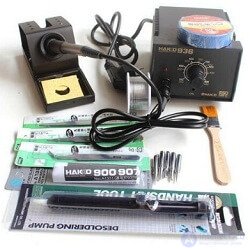
Hakko 936 soldering station with tool kit
When the wire breaks near the headphone speaker, it's best to solder it back to the headphone and redo the factory soldering. Here's how the wires are soldered inside my ancient Aiwa earbuds.
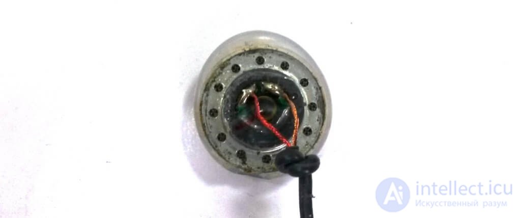
Pay attention to the tied knot — it prevents the thin wires from tearing off during tugging. Before soldering the headphone, be sure to tie the same knot at some distance, slightly greater than the distance to the narrow opening.
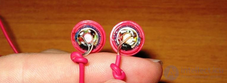
The question arises — what does the polarity of the wire connection to the speaker depend on? The answer is simple — headphones are connected identically so that they work in phase. When the headphone polarity is mixed up, the sound gets smeared and becomes quieter than when in phase. If a wire has broken in one speaker, to connect it correctly you need to look at how the wires and soldering are done in the other headphone.
What to do if the wire breaks inside the headphone
The most unpleasant thing is when the wire breaks inside the headphone. This means a break has occurred in the speaker's voice coil wire, which is shown in the figure.
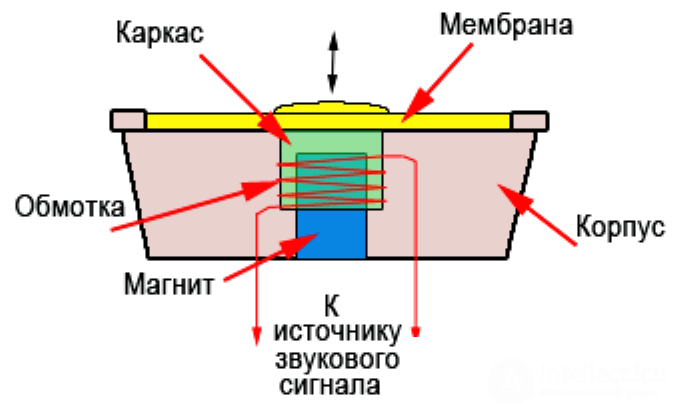
The speaker's voice coil is usually glued to the diaphragm and breaks at the point where the wires are attached to it. Over time they simply fracture from micro-movements.
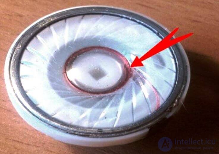
Restoring such a break is extremely difficult, but possible under a microscope. When repairing headphones, you need to be extremely careful not to tear the diaphragm and not damage the geometry of the coil. Special attention should be paid to micro-dust that has gotten between the magnet and the coil. Magnetic debris is well removed with chewing gum or modeling clay.
How to solder headphones with a microphone
To correctly repair headphones with a microphone, you need to know the wiring diagram and the pin assignments of the four-contact jack. A typical wiring diagram for the microphone plug and button in a stereo headset is shown in the picture below.
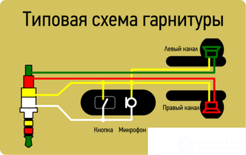
For most manufacturers of simple headsets, the microphone should be soldered as shown in the picture.
How a four-contact jack is designed
A four-contact jack has the same design as a three-contact one. A coaxial construction and separation by plastic sleeves of standard sizes into 4 wires is present in all TRRS plugs. The pinout of 4-wire plugs varies by manufacturer. Here everyone does their own thing. To correctly replace a headset plug, look at the mini-jack pinout in the picture.
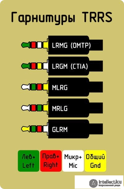
The picture uses the following designations: M — microphone, G — common contact, R — right channel, L — left channel. Now it's clear that soldering 4-wire headphones is not an easy task. The plug wiring diagram depends heavily on the headset brand.
Universal component tester LCR-T4
About wire colors in headphones
Wire colors in headphones are usually standardized. The wire colors for standard headphones with 3 wire types are shown in the photo below.
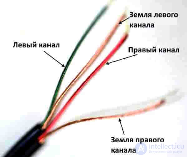
However, there are still manufacturers who use non-standard wires for soldering headphones and marking channels. For example, Apple uses two-color wire marking in its AirPods headphones.
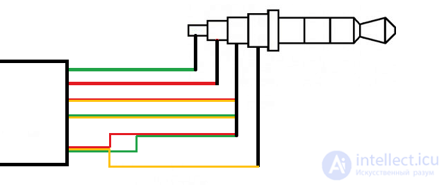
In such cases, the Internet or the method of testing with a 3-volt battery or a multimeter comes to the rescue.
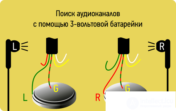
When voltage is applied (from a battery or a multimeter in ohmmeter mode) between the driver's contacts, a rustling sound will be heard in it. That's simple. It's harder with headsets, especially if they have buttons. Here circuit design comes into play, because manufacturers often use the minimum number of wire pairs to transmit a large number of signals.
How to repair headphones without a soldering iron
It often happens that a person doesn't have a soldering iron or an outlet at hand, and the headphone plug isn't working. In this case, we can re-solder the plug using several non-standard but acceptable methods.
The first method — use conductive glue to attach the wires to the mini-jack contacts. Everything is done simply and neatly. The reliability of such an attachment is of course lacking, and the electrical resistance of the glue can amount to tenths of an Ohm. With a headphone resistance of 4-16 Ohms, the glue can affect the volume of the sound. Fortunately, the drying time of conductive glue is usually 10-15 minutes.
The second method — heat a nail or a piece of copper wire in a candle flame. This is a method for romantics: dim light, candles, a plug, headphones and you. It's better to use scented candles in this case. But seriously, you can also solder a headphone plug with the help of a campfire and coals. The main thing — is to not forget good solder and flux.
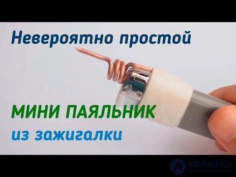
The third method — make a gas soldering iron from a lighter with your own hands. You need to take a piece of solid copper wire and attach it to the lighter so that part of the wire is in the flame. Heat is transferred along the copper wire over some distance, as can be seen in the photo.
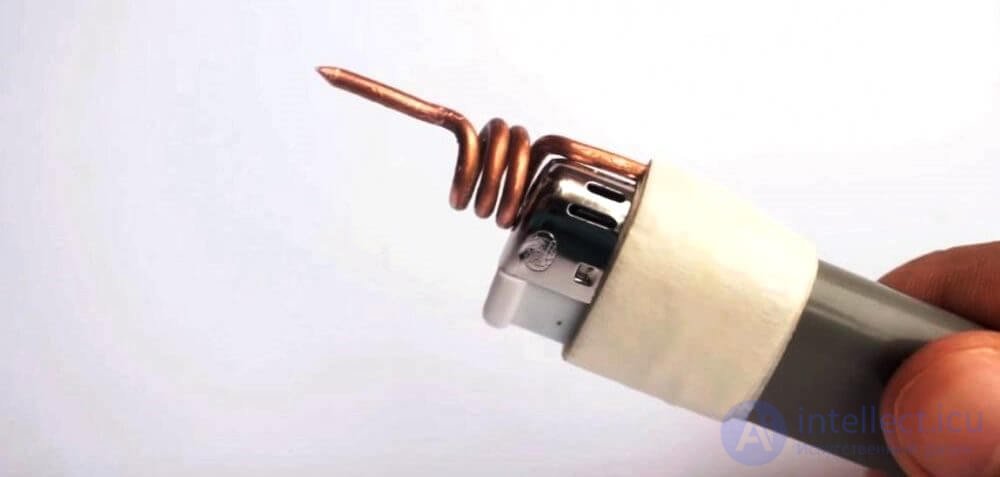
If you use this method, pay special attention to the place where the wire touches the lighter's body. A hole may form there from the heat. Be careful! For more details on how to make such a mini soldering iron from a lighter, see the video.
It seems I've covered the topic of how to solder a plug to headphones or a headset quite fully. Today we've learned how to solder headphone plugs and drivers even without a soldering iron. I look forward to your questions in the comments and on the forum.
DIY repair of stereo headphones
Stereo headphones (headsets) – are a mobile sound-reproducing device designed for individual listening to music and speech.
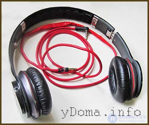
By design, headphones come in the following types:
- In-ear (earbuds, plugs, buds, in-ear monitors, earplugs), which are inserted into the ear canal;
- On-ear, which are inserted into the outer ear;
- With a headband, on which two drivers are mounted;
- With a headband, on which two drivers and a microphone are mounted (headset).
In the overwhelming majority of headphones, the audio signal is fed to the drivers and microphone via wires, and their fraying is the main cause of failure. Such headphone faults can, if desired, be easily fixed by hand, which is what this article will discuss.
Headphone electrical circuit
For successful repair of any wired headphones, you need to understand their design, electrical circuit, and wire soldering order.
The electrical circuit shown illustrates the wiring of headphone wires to the widely used ⌀3.5 mm Jack (mini-jack) connectors for audio signal transmission.
3.5 mm mini-jack plugs are widely used to transmit audio signals in headphones and microphones, sound cards of computers and tablets, cell phones, audio amplifiers and speakers.
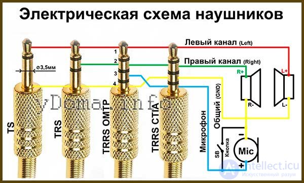
Until 2012, the pinout of 3.5 mm mini-jack connectors followed the OMTP (Open Mobile Terminal Platform) standard. On the diagram these are the TS, TRS and TRRS OMTP type jacks. Since 2012, the new CTIA (Cellular Telephone Industries Association) standard has been adopted, according to which all audio systems are currently wired; on the diagram this is the TRRS CTIA jack (shown on the right in the photo).
The polarity of the R+ and L+ channels is indicated conditionally, since the audio signal is an alternating current. But this is necessary for phasing the left and right channels. For a mono system, the audio signal is transmitted over a single wire simultaneously to two headphones connected in parallel. But the polarity of the driver connection must also be observed.
Interchangeability of 3.5 mm mini-jacks
When connecting headphones to an audio device output, it should be taken into account that, despite identical geometric dimensions, 3.5 mm mini-jacks are not always interchangeable.
If you connect stereo headphones with a TRS, TRRS OMTP or TRRS CTIA plug into a jack intended for mono headphones with a TS plug, only the left headphone will work.
When connecting mono headphones with a TS plug into TRS, TRRS OMTP or TRRS CTIA jacks, both drivers will work without stereo effect. In simple headphones the drivers are connected in parallel
The TRS plug is fully compatible for working with TRRS OMTP and TRRS CTIA jacks. But when using headphones with a microphone, called a headset, there can be problems.
Interchangeability of TRRS OMTP and TRRS CTIA
If you connect a modern headset with a TRRS CTIA plug to a device with a TRRS OMTP jack installed, the microphone will not work, and the headphones will have significant distortion. This is because the microphone input contact will be connected to the common wire, and the common contact to the microphone wire.
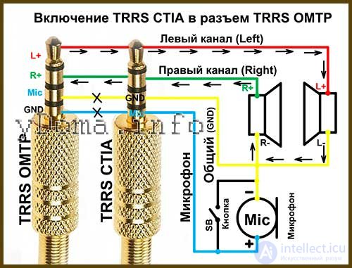
With this connection, the audio signal current can only flow through the circuit from the L+ output, through the drivers connected in series in antiphase, and to R+. The common wire signal will reach the microphone, but due to its high internal resistance it will not affect sound reproduction.
If you press the SB microphone mute button, the headphones will start working normally. If the microphone is not needed, then by locking the SB microphone mute button, the headphones can be used without harm to the equipment. But if a microphone is required or long-term use of the headset with the device is planned, then the headset needs to be disassembled and the GND and Mic wires swapped.
A similar situation will occur if a TRRS OMTP plug is inserted into a jack designed for a TRRS CTIA plug.
Color wiring of wires
In the cord coming from the plug, several wires of different colors are laid. Quality cables use a multi-strand tinsel-type wire, in which thin wires are twisted together with a nylon or linen thread, which increases the mechanical strength of the wire against stretching and bending.
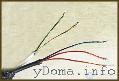
There is no international standard for wire color coding. Therefore, manufacturers solder wires to the jack terminals guided by internal documentation.
But from practice, it can be concluded that the common GND wire is not colored by any manufacturer and has the color of copper coated with insulating varnish.
Repair of in-ear headphones
Currently, wired in-ear headphones are very popular. Low price, small size and acceptable sound quality make them indispensable for use in headsets of mobile devices.
Since headphones are used while moving, the wires are constantly flexed and therefore fray over time, usually at the point where they enter the drivers, less often at the jack.
The location of a wire break is usually obvious; the sound in one of the drivers starts to periodically cut out when the wire is moved. In such a case, even without instruments it's clear where the wire has frayed. I'll give an example of a DIY repair of htc in-ear headphones.
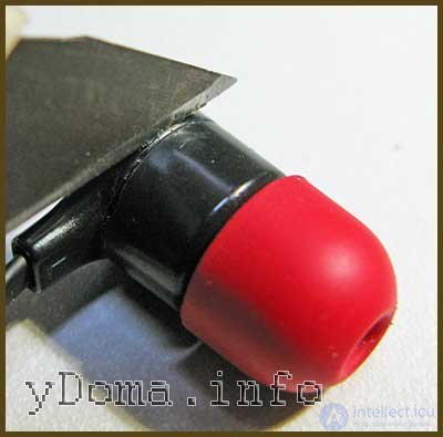
In these headphones, the wire frayed at the entry point of one of the drivers. To repair it, you need to open the housing. To do this, insert a knife blade into the gap between the halves of the housing and, turning it slightly, separate the halves.
Usually the two halves of the phone [earpiece housing] are held together by a tight fit, thanks to a groove in one part and a protruding ridge in the other, so they come apart without any problems.
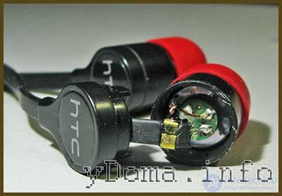
After disassembling the phone [earpiece housing], it became visible that one of the pair of wires was broken, and in the second wire part of the strands was also broken. Given that the cord was also worn at the point where it enters the earphone, the entire unusable section of it needs to be removed.
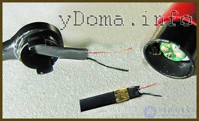
So the conductors were desoldered from the phone [earpiece housing], the cord was cut back by a couple of centimeters, and the wires were stripped of insulation. Then the retaining clip was pried open, removed, and reattached by crimping it with pliers onto the cord at a new location. The location was chosen so that when the cord is pulled taut, the soldered conductors would not be under tension.
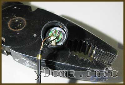
All that remains is to tin and solder the wires to the earphone driver, observing polarity. Pliers were used as a "third hand." A pharmacy elastic band was placed over the pliers' handles, providing gentle clamping of the housing.
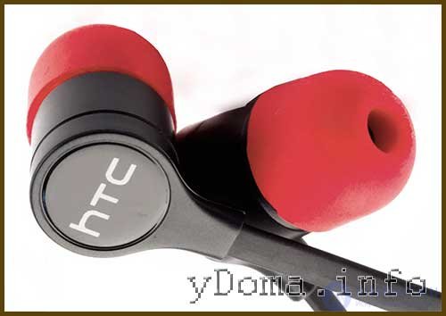
All that's left is to close up the halves and check that the earphones work. During the repair I also re-soldered the wires in the second earphone, since they would have failed soon anyway.
Repairing over-ear wireless Bluetooth earphones
The audio signal to Bluetooth earphones is transmitted over the air. Because of this, there is no connector for hooking the earphones up to the signal source. Therefore it is impossible to check the continuity of the cord wires with a multimeter.
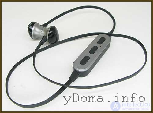
A distinctive feature of this earphone model is the presence of permanent magnets on the back cover, allowing the housings to be attached to each other. But this doesn't affect the repair procedure, though it is convenient in use.
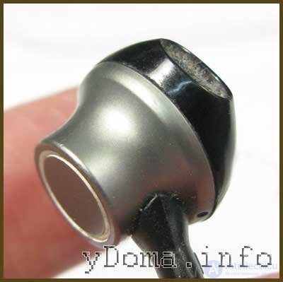
As a rule, both housings rarely fail at the same time — usually one of them starts to malfunction. The control unit is harder to open, so the fault search should start with the earphone that stopped working.
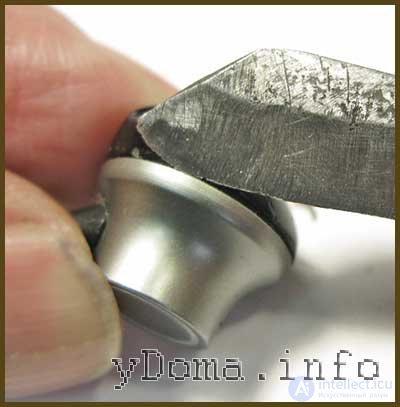
Usually the earphone housing consists of two parts held together by friction. To open the earphone, insert a knife blade into the gap between the housing halves and twist it.
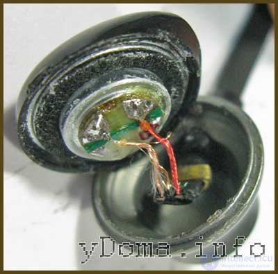
After opening the earphone, the cause of the failure was immediately obvious. The common copper-colored conductor was broken.
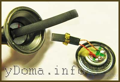
The cord was pulled into the housing and cut along the line where it enters the earphone. Often in earphones the cord frays exactly at the entry point, so to rule out a possible failure in the near future, the cord was cut at this location.
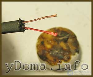
The cord's insulation was melted around the circumference with a soldering iron and removed. Here you must be careful not to overdo it and melt the nylon thread inside the tinsel conductors.
The wires are coated with a layer of varnish, which breaks down when heated. The wires tin well with solder when an aspirin tablet is used as flux. All that remains is to solder the conductors to the housing terminals, observing polarity.
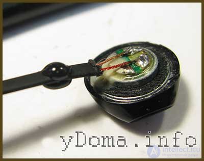
The brass clip crimped onto the cord was very stiff, and it was hard to bend open. In addition, it only secured the cord against pulling out of the earphone but allowed the cord to be pushed further in. As a result, the wire inside broke. To prevent this, the cord was secured with a drop of hot-melt glue. When the cord is pulled into the earphone's opening, the hot-melt glue will compress and firmly secure it.
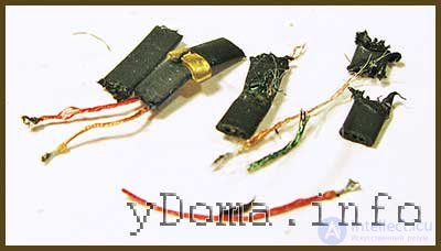
At the same time, the cord on the second earphone was also re-soldered. If a wire has frayed in one, it will fray in the other soon as well. The photo shows the cord offcuts left over after the repair.
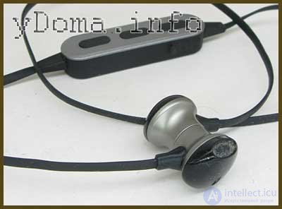
The DIY earphone repair is finished, and now they will last even longer than they did before the repair, since the design flaw that caused the earphones to fail has been eliminated.
Repairing wired earphones with microphone, CHP 510
On wired over-ear stereo headsets, the wires in the cord usually fray at the point where the cord enters the housing.
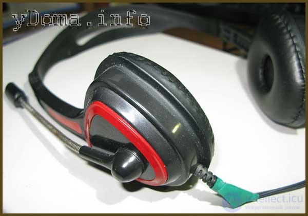
A friend of mine brought me the earphones you see in the photo, with exactly this kind of fault. He had tried repairing the earphones himself by soldering the broken wires back together, but they kept breaking again. This kind of repair only results in the earphones working for a short time.
For a proper repair it is necessary to cut off the frayed cord, disassemble the earphone, and solder the wires directly to the sound driver.
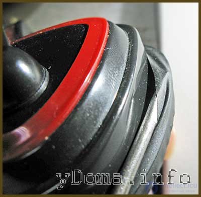
Disassembly of the earphone should start with removing the ear cushion. To do this, pull it away from the edge with your fingers, and using the blade of a flat screwdriver, pry it free from engagement with the housing.
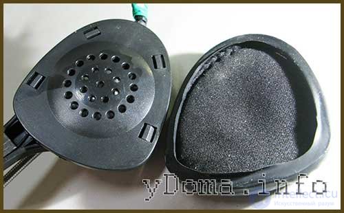
After removing the ear cushion, four latch tabs became visible. Sometimes the housing cover is held on with screws instead.
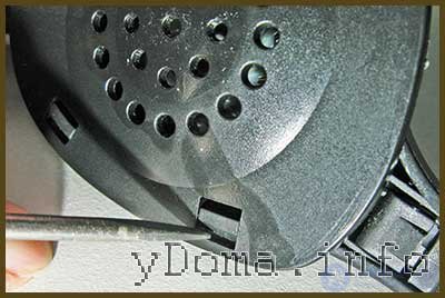
To remove the cover, press on each latch tab in turn with a flat screwdriver toward the center to release it.
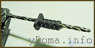
After cutting off the frayed section of the cord, I found that it was fused solidly into the elastic tubing that protects it from sharp bending. I had to remove the wires from the tubing with a drill bit. After clearing it out, the tubing was put back onto the cord.
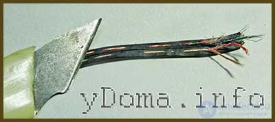
Next, very carefully, so as not to damage the wire strands, the insulation is cut away with a knife. A soldering iron won't help here, since the conductors are practically fused into the insulation, and it was impossible to slide it off the wires.
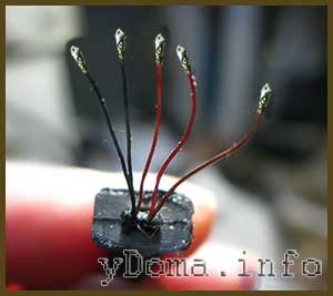
After being freed from the PVC insulation, the ends of the conductors need to be tinned using a soldering iron and flux. The photo shows the cord prepared for soldering into the earphone.
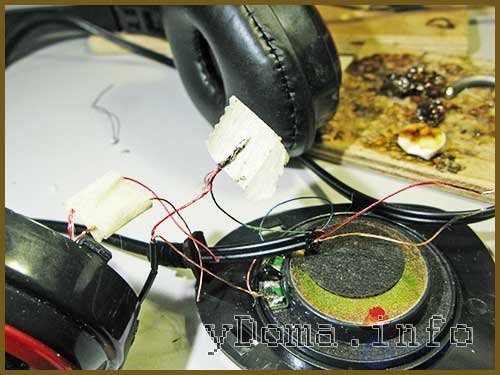
So as not to get confused about the markings, the faulty wires were not desoldered ahead of time; instead, at the moment of soldering in a new one, the old one was desoldered and a wire of the same color was soldered in its place.
The wires going to the speaker of the opened earphone were soldered directly to its terminals. Those going to the second earphone and the microphone were joined to each other by soldering the wires together. For insulation, the paper tape with an adhesive coating that was already there was reused.
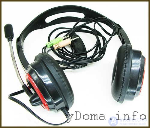
The photo shows the self-repaired CHP 510 earphones, which will hopefully serve for many more years
Repairing headband earphones with microphone, Genius
Genius earphones came in for repair, in which the wires were frayed and the mounts attaching the housings to the headband were broken.
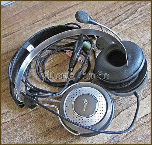
The earphones were brought to me for parts, but after assessing their technical condition, I concluded that they were repairable.
Repairing the mount attaching the earphone housings to the headband
Before repairing the worn-through wires, first it was necessary to repair the mechanical damage to the assemblies attaching the earcups to the headband.
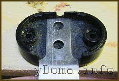
Opening up the assemblies showed that the tabs used to secure the flat headband spring were missing. It looks like the headphones had been dropped, and the flat spring had simply sheared them off.
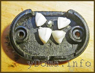
The spring could be secured in the assembly using two screws, but for reliability I decided to use a combined type of fastening – one screw and thermal glue. To do this, a hole was first drilled in one of the halves and an M3 screw was inserted into it.
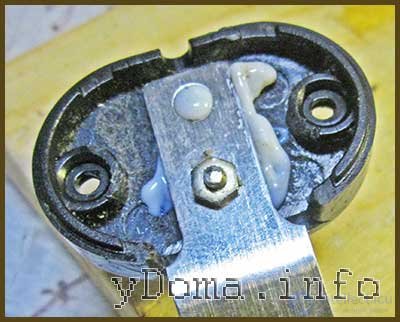
Next, pieces of thermal glue were melted with an electric soldering iron, and before the glue cooled and hardened, the headband spring was installed and a nut was screwed onto the screw. The second assembly was repaired in the same way.
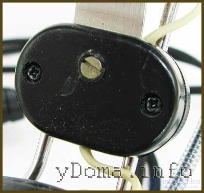
The thickness of the plastic of the assembly made it possible to use a screw with a conical head, which was melted into the drilled hole using a soldering iron. If desired, the screw head can be coated with black lacquer.
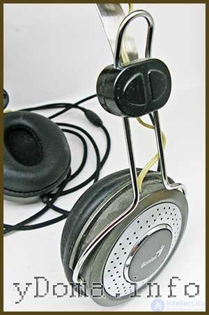
As can be seen in the photograph, the external appearance of the headphones has not changed. The ability to adjust the headband length has been preserved. Now the earcups are securely attached to the headband, and we can proceed to repairing the cord.
Repairing the headphone wires
The headphones could not be tested with a multimeter through the jack, so the earcups had to be disassembled. Disassembly begins with removing the ear pads from the earcups.
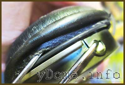
To do this, you need to grip the edge of the ear pad and pull it off by hand. Next, pry up the ear pad with a screwdriver and carefully work it out of engagement with the earcup housing all the way around.
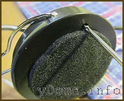
To disassemble the earcup it is enough to unscrew three screws and the cover comes off. But one of the screws turned but would not unscrew.
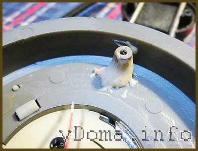
It turned out that one of the threaded posts had broken off. It had to be replaced with a metal post with an internal thread, fitted using thermal glue.
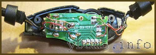
A volume control and microphone mute unit is installed on the headphone cord. To determine, using a multimeter, at what point the wire was broken, the unit had to be disassembled. For this it was enough to unscrew two self-tapping screws.
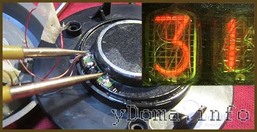
Testing with the multimeter showed that the speakers in the headphones were functional and had a resistance of 31 Ohms. And the wires in the cord had a break both on the section between the jack and the volume control, and from the volume control to the earcups. It was necessary to cut off a section of the cord, both at the earcup and on both sides of the volume control, and re-solder the wires.
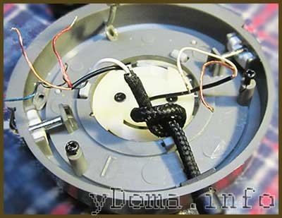
The limitation on the cord being pulled out of the earcup housing had been made by tying it into a knot. This is a poor solution, since the cord is still able to move inward and rotate, which can cause the wires to break.
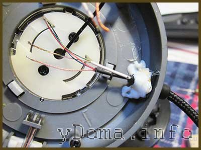
Therefore, the cord was secured with thermal glue. First, glue was applied to the cord, which was pulled into the bushing before the glue hardened. Then the cord was fixed to the earcup cover with thermal glue.
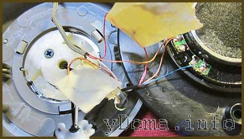
It remained to solder the wires according to the color coding, screw the earcup halves together, and put the ear pad back on.
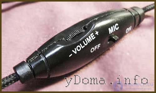
Now it was time to repair the volume control and microphone mute unit. On this headphone model, unscrewing just two screws was enough to open the unit.
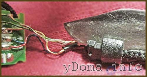
The cords in the unit were secured with plastic bushings, which could not be removed from the cord. So the bushings were cut lengthwise with a knife.
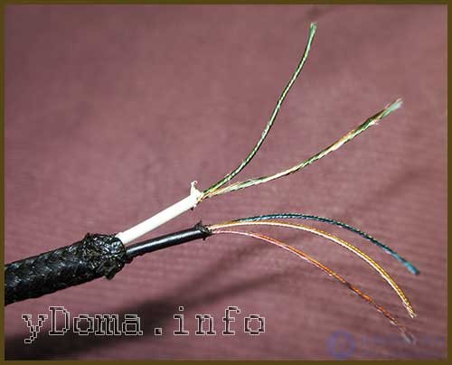
Next, sections of the cord were cut off and the insulation was removed by melting it with a soldering iron. It is worth noting that the wires carrying the audio signal to the earcups and to the microphone were, in order to reduce mutual interference, insulated from each other.
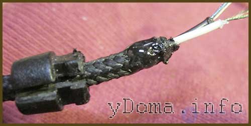
To secure the bushing on the cord, a drop of thermal glue was applied to it; superglue could also be used. But thermal glue hardens faster.
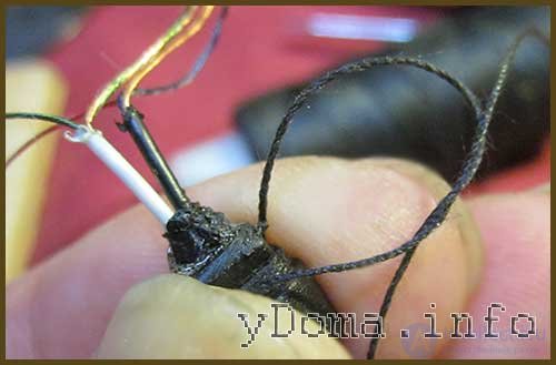
Next, before the thermal glue hardened, the bushing was slid onto the glue and compressed by wrapping it with a turn of thread.
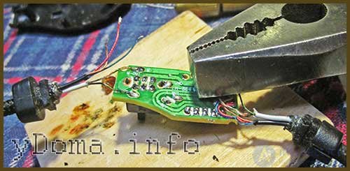
It remained to solder the wires to the printed circuit board contact traces and assemble the control unit. To make it convenient to solder, I clamped the board with pliers. At the same time, the volume control was also lubricated with machine oil.
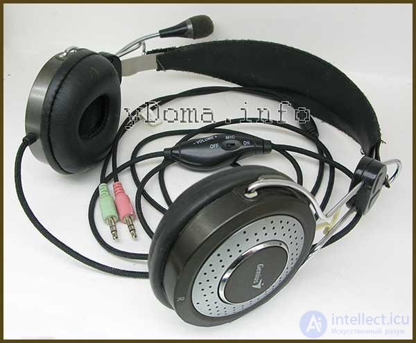
The DIY repair of the Genius headphones with microphone is complete. Testing showed they work correctly. Now, with careful handling, the headset will last for many more years.
Repairing Panasonic RP-WF83 wireless headphones
I had to repair Panasonic RP-WF83 wireless headphones, which worked normally, but the batteries located in the earcups would not charge from the base.
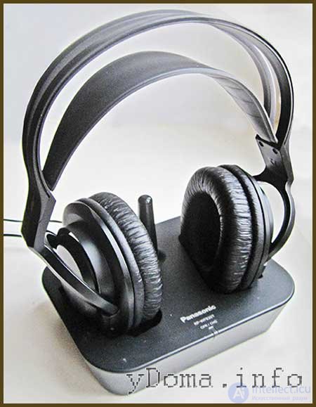
They had to be taken out and charged from a separate charger, which was inconvenient.
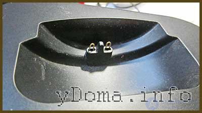
In one of the recesses of the base with the transmitter there were two spring-loaded contacts, through which the charging current was delivered to one of the earcups. Measuring the voltage on these contacts with a multimeter set to DC voltage measurement mode showed that the charger circuit in the base was functional.
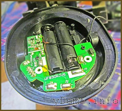
Consequently, the fault is in the earcup itself. To get to the electronics you need to remove the ear pad and unscrew the self-tapping screws, as described in the article above. Upon inspecting the board, the cause of the failure immediately became clear.
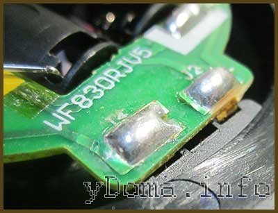
The copper traces, to which the contacts for connection with the base were soldered, had been torn away from the board. Considering that only the pressure of the base's movable contacts was applied to them, the failure occurred due to a design flaw. The contacts were soldered in such a way that pressure on them transferred force that tore the traces off.
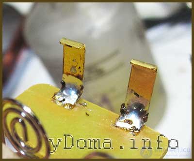
The torn-off copper pads were glued to the board with Super-Moment glue. Next, as shown in the photograph, they were coated with a layer of solder.
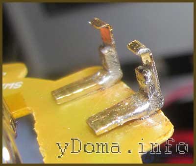
Two support corner brackets were made from a brass plate, tinned with solder and soldered on the inside of the contacts. The brackets can be made from any metal, iron will also work, the main thing is that the metal can be tinned with solder.
Now the entire force of the pressure will be applied not to the point where the contacts are soldered to the PCB, but to the installed corner brackets.
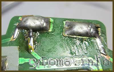
The cracked traces were simply tinned and covered with a thick layer of solder. If a trace is severely damaged, it can be duplicated with a copper wire.
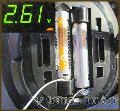
To check the battery charging, wires were connected to the contacts and hooked up to a voltmeter, which showed a voltage of 2.61 V. This indicated that the batteries were charging, since their working voltage cannot exceed 2.5 V.
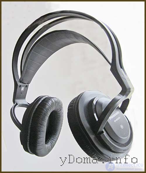
Practical use of the earphones has shown stable battery charging. The DIY repair of the wireless earphones is complete, and now they will never again fail due to broken contacts.
Other faults in wireless earphones
Wireless earphones, thanks to the absence of a cord, rarely break. They usually stop working when the batteries or accumulators are discharged. It also happens that the battery contacts oxidize, in which case they need to be cleaned with alcohol, or even vodka will do.
If the power switch on the earphone starts working unstably, it needs to be flushed by dripping a drop of alcohol inside and switching it on and off repeatedly. If that doesn't help, it will have to be replaced with a working one.
If crackling appears or the sound cuts out when adjusting the volume, then also first drip a drop of alcohol inside it, and after repeatedly turning the wheel, drip in some machine oil.
I was recently looking into the wiring diagrams of wired headsets with a 3.5 mm mini jack. Information online is contradictory, for example here and here, but in the end I found out that there are at least two wiring standards. They differ in the connection of contacts 3 and 4 (common wire and microphone)
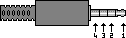
Here is the diagram of a headset with three buttons (with one it's the same, just a single button) for the latest HTC models (verified on my own Touch2), 3-common, 4-microphone/button:
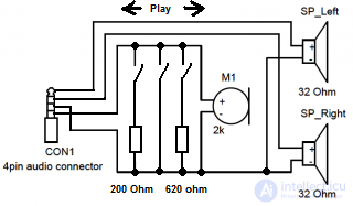
Apple, LG, Samsung and others have the same wiring diagrams.
Nokia has a different diagram, with 3-microphone/button, 4-common:
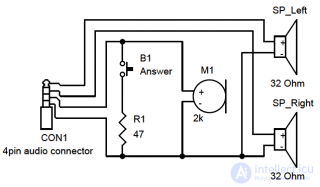
It's clear from the diagram that the answer button shorts contacts 3 and 4, so with the button pressed the earphones work normally in both cases.
The conclusion is this - test the headset before buying it on your own device, or at least find out in advance which type is needed and go by the list of supported models (if you have an iPhone, it's definitely the first diagram).
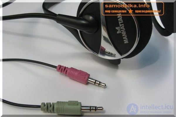
In this article I will explain how to repair earphones or a headset for a computer or mobile phone yourself. We will look at the main types of faults and ways to fix them.
Main earphone faults:
- wire break
- connector plug damage
- microphone faults
- speaker faults
- volume control fault
- earphone headband (suspension) breakage
- microphone mount (boom) breakage
Repairing an earphone wire break
A wire break is the most common cause of earphone failure. To repair the wire we will need:
- soldering iron;
- solder;
- scalpel or wire cutters;
- heat-shrink tubing;
- hot-melt glue;
- thread.
First, it's necessary to determine the location where the break occurred, since the outer rubber sheathing may not have any externally visible deformation. You can find the location of the wire break by connecting the earphones to an audio source and bending the wire from the plug to the speakers, finding the spot where bending causes sound to appear in the earphones. Having determined the break location, we cut out a section of wire, taking a few centimeters before and after the break point. Next, we strip the wire of its outer insulation and tin the wires. How to tin an earphone wire is a fairly relevant question. I will now explain how to do this well and quickly. For this we will need: a wooden board, flux (for example organic flux F-99), solder and a soldering iron.
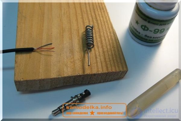
We apply flux to the wire, lay the wire on the board and press it down for a few seconds with the soldering iron, making motions as if you're scraping the lacquer off the wire.
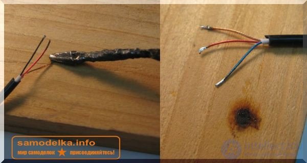
Having tinned all the wires, we put a thin piece of heat-shrink tubing on each wire, solder the wires together while matching the color scheme, and using a lighter or the soldering iron shrink the heat-shrink tubing.
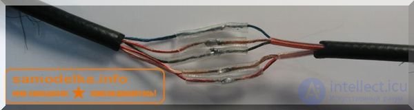
The heat-shrink tubing acts as an insulator and prevents the wires from shorting against each other. Now we need to ensure the strength of our connection. To do this we fold the wires into a Z shape and use thread to bind our connection.
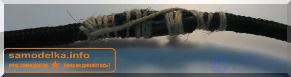
The last stage of repairing the headset wire has a practical-aesthetic purpose. Using the soldering iron, we carefully apply hot-melt glue to our binding; on one hand the hot-melt glue will keep the thread from unraveling, and on the other hand it will give the wire connection a decent appearance. If you can't get black hot-melt glue, you can put a heat-shrink tube of the appropriate diameter over the binding instead.
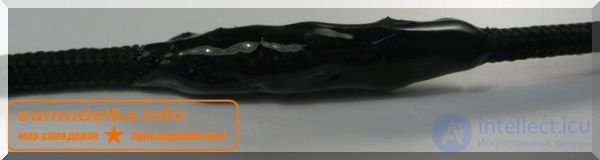
A couple more words about artistic shaping with hot-melt glue: if you heat the hot-melt glue and wet your fingers with water, you can shape it into any form with your fingers before it fully hardens. Uneven spots can be made glossy using a lighter.
Connector plug (jack) damage
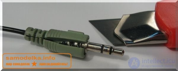
Before repairing the plug we need to carefully disassemble it; to do this we carefully use a scalpel to make a cut along the housing. Damage to the earphone plug (connector) can be divided into faults related to mechanical deformation:
- the last segment breaking off - as a rule this segment stays inside the mating part of the device and can only be extracted using an awl and tweezers for SMD assembly. This kind of damage can only be fixed by replacing the plug.
- rotation of the first (common) segment around its axis - characterized by the sound changing to "metallic underwater" and a drop in volume. In this case the repair consists of resoldering the contact between the segment and the contact tab.
And faults not related to mechanical deformation of the plug - this is a wire break at the base. It is fixed by shortening the wire by a couple of centimeters above the break point and soldering it back into place while matching the color scheme.
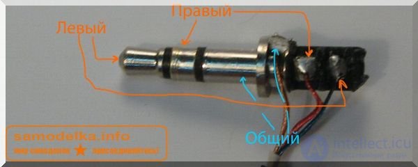
If you broke a wire and don't know which one was soldered where, don't despair! With a multimeter you can easily determine this. Set the multimeter to resistance measurement mode and, one at a time, find the 2 pairs of wires between which you see an equal value (this depends on the resistance of your speakers' coils and typically lies in the range of 16-100 Ohm. Take one wire from each pair, twist them together, this will be the common wire, and solder it to the first (most massive) segment. Solder the remaining wires to the 2nd and 3rd segments. You probably have a question about how to determine where the right channel is soldered and where the left one is. You can check the correctness of the connection by connecting the earphones to a computer, opening the sound settings, and clicking on the left and right channel indicators one at a time. There is a second option: launch an audio player, for example Winamp, and adjust the balance, comparing it with what you hear to conclude whether the channels are connected correctly.
Microphone fault

Headsets use capsule electret microphones. Inside the microphone there is an amplifier, which necessitates observing polarity when connecting the microphone. Microphones are sensitive to diaphragm deformation, so do not try to clean the hole in the microphone. Also, microphones are very sensitive to high temperatures, so resoldering the microphone must be done quickly and carefully. Before you start soldering, it is advisable to apply organic flux to the microphone contacts, as this will improve heat transfer and reduce the soldering iron contact time needed for a reliable joint. The only way to check whether a microphone is functional is to replace it with another one, or connect it to another device that is known to work. Still, you can check whether a microphone works if you have an oscilloscope (or an active speaker system) and an operational amplifier chip (any type) at your disposal — you can build a simple circuit (for example, an inverting amplifier with single-polarity power supply.
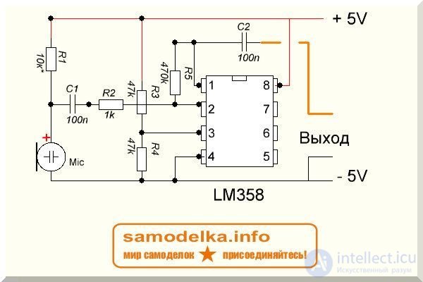
Don't forget that the microphone needs to be powered through a resistor, and the signal must be taken off through a coupling capacitor with a value of 0.1 uF. This circuit will let you clearly see whether the microphone is working — the amplified signal from the microphone will change the picture on the screen in time with your voice. If there is no oscilloscope, you can connect the output of the circuit to an active speaker system — if the microphone is alive, you'll get a megaphone.
Repairing headset speakers.
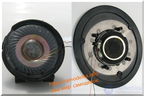
If the applied power is exceeded, the speaker can fail — the winding wire burns out inside it. The integrity of the speaker's winding is checked using a multimeter.
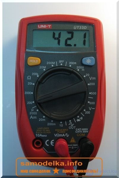
For a working speaker, the winding resistance will be equal to the winding resistance of the second speaker +\- 10%. As a rule, this value is 16-100 Ohms. If sound is present in the speaker but with a rattling/rasping noise, this means the winding is intact, but it has either come unglued from the diaphragm or is catching on the magnet. This can be the result of an impact (magnet displacement), or the result of exceeding the power rating (the lacquer on the winding boiling and "snagging" on the magnet, as well as part of the coil coming unglued from the diaphragm). This kind of repair requires care. The coil can be glued to the diaphragm using superglue, which can be applied with a toothpick or a sharpened matchstick. To avoid the diaphragm jamming, do not join the speaker housing and diaphragm until the glue has fully dried. Drying can be sped up by placing the speaker under a desk lamp.
Repairing the headphone volume control.
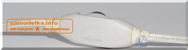
One of the weakest points of headphones is the volume control, given frequent use. The volume control is a dual-gang variable resistor consisting of 2 strips of resistive coating and 2 wipers moving across the surface of the resistive layer as the control wheel is turned.
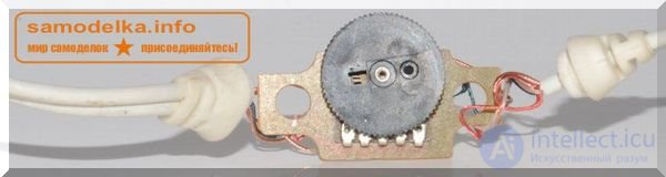 During use, dust gets onto the surface of the resistive layer, which causes poor contact between the wiper and the resistive layer. This fault shows up as crackling when adjusting the volume level, or as the signal in the headphones dropping out. Repairing the volume control consists of applying graphite grease or technical petroleum jelly to the surface of the resistive layer. This restores reliable contact and eliminates the crackling when turning the control.
Repairing headphone headbands (the suspension on which the speakers are mounted).
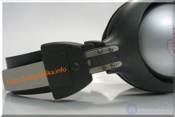 A broken headband is one of the most common failures. Some manufacturers, betting on the quality of their products, have already reduced the chance of this kind of failure in their headsets to 0. Instead of classic plastic headbands, they use flexible metal spring suspensions coated with a layer of PVC or rubber. But here we're talking about the classic plastic suspension and how to repair it.
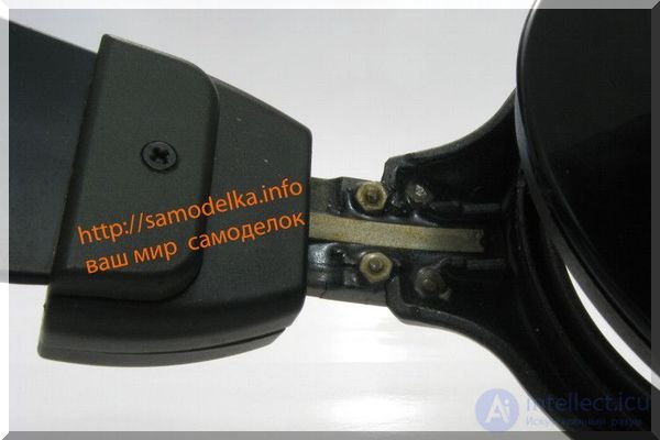 In the photo we see that the headband is broken in half. To repair it we'll need several thin metal plates, M2 or M3 screws, 2-component epoxy glue, and a drill. First, we place our plates against the headband and use a marker or pencil to mark where we'll need to drill holes. We drill holes in the headbands and plates and pull the assembly together with the screws. Note that the metal plates are fairly long and do not end right after the screw hole — this adds strength to the assembly under load. Also note the 3rd plate, located on the back side of the headphones. It is installed before pouring the epoxy glue, and is also meant to increase the strength of the headphones and their resilience to the trials ahead.
Repairing the microphone mount.
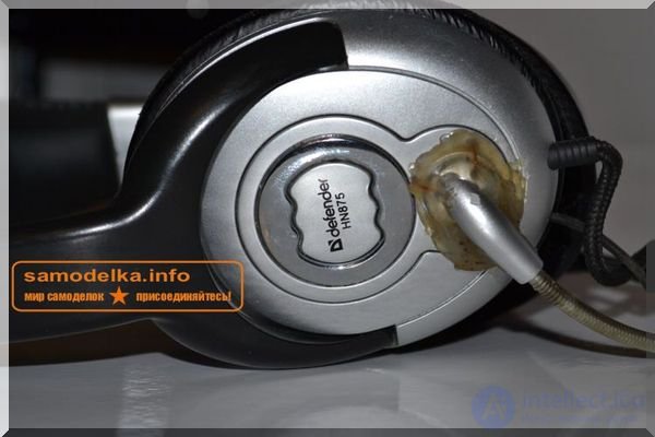 The microphone mount (the boom, the "antenna") is usually made flexible and fairly resistant to mechanical damage, but it can still be broken. In the photo we see that as a result of the headset being dropped, the plastic base of the microphone mount was damaged. Its function was to adjust the position of the microphone in the vertical plane. Naturally, full functionality cannot be restored, but it is quite possible to reliably fix the microphone in one position. For this we'll need: a drill, wire with a diameter of 0.6-0.8 (mm), and hot glue. Having determined the optimal position for the microphone mount, we mark the spots where we'll drill the holes. Then, using the wire, we tightly bind (stitch) together the mount base and the headphone housing at 3-4 points. We twist the wire on the inner side of the headphone using pliers. Then we apply hot glue on top, shaping it as needed with fingers moistened with water. After that you can take nail polish or spray paint and coat the repaired spot.
Send us your articles about DIY projects, or register and publish them yourself.
See also:

Comments