
Lecture
Technical diagnostics is a branch of scientific and technical knowledge whose essence consists of the theory, methods, and means of detecting and locating defects in objects of a technical nature. A defect should be understood as any discrepancy between the properties of an object and its specified, required, or expected properties. Defect detection is establishing the fact of its presence or absence in an object. The search for a defect consists in indicating its location in the object with a certain accuracy.
The main purpose of technical diagnostics is to increase the reliability of objects at the operating stage, as well as to prevent manufacturing defects at the object and part production stage. Any technical object, after design, goes through two main stages of "life" – manufacture and operation. With regard to the tasks solved by technical diagnostics, at the manufacturing stage it is advisable to distinguish the periods of acceptance of component products and materials, the production process, adjustment, and handover of the object to quality control (QC) or the customer's representative. For the operation stage, the typical stages are use of the object as intended, preventive maintenance (scheduled, before and after use as intended), repair, transportation, and storage of the object.
The requirements that a manufactured (new) or operated object must satisfy are determined by the relevant regulatory and technical documentation. An object satisfying all the requirements of the regulatory and technical documentation is serviceable, or is said to be in a serviceable technical condition. It is necessary to verify the serviceability of an object after its manufacture and after repair.
For operating conditions, the concept of the operable technical condition of an object is of practical importance. An object is operable if it can perform all the functions assigned to it while maintaining the values of the specified parameters (indicators) within the required limits. It is necessary to verify the operability of an object, for example, during its preventive maintenance, after transportation and storage.
Finally, for the stage of use as intended, the concept of the technical condition of correct functioning of an object is significant. An object is functioning correctly if the values of its parameters (indicators) at the current moment of real time of its use as intended are within the required limits (at this moment in time the object has not failed, i.e. it correctly performs a specific assigned function).
Faulty and inoperable technical condition, as well as the technical condition of incorrect functioning of an object, can be detailed by indicating the corresponding defects that violate serviceability, operability, or correctness of functioning and that relate to one or several constituent parts of the object, or to the object as a whole.
The detection and localization of defects are processes of determining the technical condition of an object and are combined under the general term "diagnosing"; a diagnosis is the result of diagnosing. Thus, the tasks of diagnosing are the tasks of checking the serviceability, operability, and correct functioning of an object, as well as the tasks of locating defects that violate serviceability, operability, or correct functioning.
Diagnosing the technical condition of any object is carried out by one or another diagnostic tool. The tools can be hardware-based or software-based; a human operator, inspector, or adjuster can also serve as a diagnostic tool. The tools and the object of diagnosis, interacting with each other, form a diagnostic system. A distinction is made between test and functional diagnostic systems. In test diagnostic systems, specially organized test stimuli are applied to the object. In functional diagnostic systems, which operate during the use of the object as intended, the application of test stimuli is, as a rule, excluded; only working stimuli provided for by its functioning algorithm are received by the object. In systems of both types, the diagnostic tools receive and analyze the responses of the object to input (test or working) stimuli and produce a diagnostic result, i.e. they make a diagnosis: the object is serviceable or faulty, operable or inoperable, functioning correctly or incorrectly, has such-and-such a defect, or such-and-such a constituent part of the object is damaged, etc. Test diagnostic systems are necessary for checking serviceability and operability, as well as for locating defects that violate the serviceability or operability of the object. Functional diagnostic systems are necessary for checking correct functioning and for locating defects that violate the correct functioning of the object.
In the process of determining the technical condition of an object, a diagnostic system implements a certain algorithm (test or functional) of diagnosing. The diagnostic algorithm, in the general case, consists of a certain set of so-called elementary checks of the object, as well as rules establishing the sequence for carrying out elementary checks, and rules for analyzing the results of the latter. Each elementary check is defined by its own test or working stimulus applied to or received by the object, and by the set of test points from which the object's responses to this stimulus are taken. The result of an elementary check is the specific values of the object's response signals at the corresponding test points. A diagnosis (the final conclusion about the technical condition of the object) is made, in the general case, based on the totality of the results obtained from the elementary checks.
The effectiveness of diagnosing processes is determined not only by the quality of the diagnostic algorithms, but also, to no lesser degree, by the quality of the diagnostic tools. The latter can be hardware-based or software-based, external or built-in, manual, automated, or automatic, specialized or universal.
The selection or development of test diagnostic tools should be carried out taking into account many factors: the availability of series production of the required tools, the availability of suitable tools at the object's manufacturing plant, the scale of production of the object and its complexity, the required performance of the tools, etc.
Functional diagnostic tools are, as a rule, built-in and are therefore developed and created simultaneously with the object.
The specifics of solving diagnosing tasks are determined, first of all, by the characteristics of the objects. In technical diagnostics, it is customary to distinguish two classes of objects: discrete and analog.
For discrete objects, one of the main tasks of technical diagnostics has been and remains the task of test construction.
For the first period of development of technical diagnostics of discrete objects, it was characteristic to strive to obtain optimal or optimized solutions (in particular, tests of minimal length) based on the representation of combinational objects by fault function tables, and of sequential objects – by transition-output tables. The main defect model was the class of stuck-at faults, and the main methods of test construction were enumeration methods (methods of obtaining coverings, methods of the theory of experiments on automata).
The second period of development is characterized by the abandonment of the aforementioned "refined" formulations of test construction problems, a transition to structural and structural-analytical models of discrete objects and to new methods of processing these models, and the abandonment of test optimization. This same period saw the development of probabilistic methods of test construction. All this was caused mainly by the increase in the dimensionality of practical problems.
The third period of development is associated with the emergence of large-scale and very-large-scale integrated circuits, microprocessor sets, and other products of high integration level. The high dimensionality of the problems led to the necessity of a functional representation of discrete objects at the macro level, consideration of functional faults instead of stuck-at faults, and the wide application of a probabilistic approach to test construction, etc.
This dynamic in the development of test construction methods was accompanied by a corresponding development of computer-aided tools for test construction and diagnostic modeling of discrete objects. Initially, a deterministic approach to test construction prevailed, with a gate-level representation of object structures. The acceleration of test construction procedures was facilitated by the application of a probabilistic approach while retaining computer modeling for the purpose of evaluating the effectiveness of the resulting tests. Modern computer systems, as a rule, combine both approaches – deterministic and probabilistic. Interest in deterministic test construction persists to this day. The use of powerful high-speed computers has made it possible to substantially raise the "ceiling" of the dimensionality of the test construction and diagnostic modeling problems being solved. Further progress in this direction can be achieved by problem-oriented multiprocessor computing systems specialized in solving problems of diagnostic support for complex discrete objects.
The significantly wider variety of physical principles for implementing analog objects, compared to discrete technology, complicates the development of general theoretical and methodological approaches to diagnosing the technical condition of objects of this class. Widely used diagnostic models of analog objects include their logical models and graphs of cause-and-effect relationships. These models are suitable in cases where it is possible to organize diagnosing based on the principles of tolerance-based monitoring of the object's parameters. Electrical circuits, as diagnosing objects, can be represented by models developed within the framework of general electrical engineering, and known methods for calculating such circuits are used to analyze these models for the purpose of constructing diagnosing algorithms.
To determine the operability of a product, locate defects, and predict the condition of equipment, it is necessary to measure diagnostic parameters. The measured diagnostic parameters are selected from the set of fundamentally possible parameters of a certain limited quantity for studying the informativeness of the indicators formed on these parameters. The basis of the logical diagnosis procedure is the set of physical quantities, the measurement of which determines the structural diagnostic parameters of the objects. As modern equipment becomes more complex and requirements for its reliability increase, the number of monitored structural parameters and the necessary measuring tools increases.
Of the greatest practical interest are the design and reliability parameters of objects that are functionally dependent on measurable physical quantities. For example, detection of a defect in the form of a crack and determination of its parameters can be performed by measuring the magnetic permeability, coercive force and magnetic induction of a ferromagnetic material (magnetic testing methods), the thermal conductivity and heat capacity of the material (thermal testing methods), the elastic modulus, density and specific acoustic impedance of the material (acoustic testing methods, etc.).
Measurement of physical parameters forms the basis of various methods and means of technical diagnostics, by means of which the technical condition of an object is analyzed and assessed.
All known types of electromagnetic radiation are used to study the technical condition of an object. Numerous acoustic, sound and vibration testing methods, as well as corpuscular radiation (neutrons, protons, electrons, positrons) and electrostatic fields, have found wide application. Many methods and means of diagnosing electrical and electronic equipment are based on measuring electrical quantities.
A wide range of test equipment is used to diagnose objects, including instruments for determining the hardness and elastic constants of materials, for studying the effects of climatic factors, and machines for testing materials under tension and compression, bending, impact, shear, torsion, etc.
The prospects for the development of methods and means of technical diagnostics are linked to the optimal use, for measurement purposes, of known physical phenomena and effects, as well as to the study of new possibilities arising from the development of physics. The following types of measurement are the most significant and most commonly encountered in the practice of technical diagnostics of equipment: electrometry, and measurement of vibration, noise, mechanical properties, material composition, dimensions, forces, deformations, pressure, temperature, time, mass, humidity, flow rate and level.
Measurement of electrical and magnetic quantities. The basic methods for measuring electrical quantities are direct evaluation and comparison (differential, null, substitution, opposition, coincidence).
Depending on the method used to obtain measurement information signals, instruments for measuring electrical quantities are divided into analog and digital. The most common measurements are those of DC and AC voltage and DC and AC current.
Measuring transducers (MTs) are designed for the linear conversion of the basic parameters of DC and AC electrical networks (in particular, DC current, AC current, DC voltage, AC voltage, frequency, phase shift angle and power factor, active and reactive power of both single-phase and three-phase circuits, as well as insulation resistance) into unified signals: a DC voltage of 0–10 V at a load of 2 kOhm or higher, and a DC current of 0-5 mA at a load of up to 2.5 kOhm.
An electrical circuit is an interconnection of electrical energy sources and loads through which electric current flows. Under certain assumptions, a circuit can be considered as consisting of lumped linear elements – resistors, capacitors, inductors, etc. To assess the electrical properties of a circuit, it is necessary to measure the parameters of its components. The parameter of a resistor is its resistance, of a capacitor – its capacitance, of an inductor – its inductance.
Depending on the object of measurement, the required accuracy of the result, the range of operating frequencies, and the permissible voltage on the object being measured, various measurement methods are used. The voltmeter-ammeter method, the direct evaluation method and the bridge method have found the widest application in measuring the parameters of linear elements.
Traditionally, electromagnetic measuring transducers are divided into transducers for measuring the parameters of a static magnetic field and transducers for measuring the parameters of an alternating electromagnetic field. Moreover, a number of transducers can be used to measure the parameters of both constant and alternating magnetic fields. For example, a stationary inductor coil can be used for measurements in alternating magnetic fields, while moving this coil allows measurements to be made in static magnetic fields. Hall sensors can also be used to measure both constant and alternating magnetic fields. Registration of changes in magnetic field parameters can be carried out in transducers in four ways:
- as a change in the parameters of the transducer's electrical circuit (galvanomagnetic);
- as an EMF of electromagnetic induction induced in the measuring winding (induction);
- as a change in the parameters of the transducer's magnetic circuit (magnetomodulation);
by a combination of the three preceding methods (combined).
The first group of transducers includes Hall transducers, magnetoresistive, galvanomagnetic-recombination, magnetodiode, magnetotriode, Z-element transducers, in which the action of a magnetic field causes a curvature of the trajectory of charge carrier motion, a change in their concentration, etc., which manifests itself as the occurrence of a Hall EMF or a change in electrical resistance, and superconducting transducers. In superconducting transducers, the action of a magnetic field causes oscillation of the current in the Josephson junction, i.e. the junction between two superconductors separated by a thin insulating layer. The output signal of these transducers is a change in the parameters of the electric current or voltage.
The second group includes passive induction transducers and eddy-current transducers without a core or with a core designed to concentrate the magnetic field. The magnetic parameters of the core are considered constant within the operating range of magnetic field variation. The output signal of passive induction transducers and transformer-type eddy-current transducers is the EMF induced in the measuring winding, while the output signal of parametric eddy-current transducers is the introduced complex impedance. From the standpoint of theoretical electrical engineering, the EMF induced in the winding and the introduced complex impedance are equivalent.
The third group includes transducers whose operation is based on detecting changes in the parameters of the transducer's magnetic circuit, which usually consists of the transducer's core and an external section formed by the region under test. In addition to transducers in which the change in the magnetic circuit parameters occurs under the action of an external magnetic field (fluxgate transducers), this group also includes transducers whose magnetic circuit parameters change depending on changes in structure, mechanical properties, geometric parameters, mechanical stresses – magnetoelastic, magnetoanisotropic and others. The output signal is usually the EMF in the transducer's measuring winding or the EMF of a special measuring Hall sensor or fluxgate.
Temperature measurement. Temperature – a physical quantity defined as a parameter of the thermodynamic equilibrium state of microscopic systems. Temperature is an extensive quantity, i.e. one measured indirectly by converting it into some intensive (directly measurable) quantity, for example, electric current. Methods of temperature measurement are conventionally divided into two large groups – contact and non-contact, which in turn are subdivided according to the physical effects underlying their operating principle. Contact and non-contact methods are used to measure temperature. Contact temperature measurement is carried out using liquid and manometric thermometers, thermocouples, resistance thermometers, and thermal indicators.
The operation of thermal indicators is based on the change in the state of aggregation and the brightness of the glow color of certain substances when heated. They can be used to quickly and economically obtain information about the thermal condition of an object. The advantage of thermal indicators is the ability to record the temperature distribution during testing, as well as simplicity, clarity, and economy.
Liquid crystal thermal indicators are organic compounds that simultaneously possess the properties of a liquid (fluidity) and a solid crystalline body (anisotropy, birefringence). When the temperature changes, the liquid crystal changes color.
Melting thermal indicators exist in two types: fusible coatings and thermal witnesses. Coatings are produced in the form of thermal pencils (crayons), thermal lacquers, and thermal tablets (thermal powders). They are made on the basis of wax, stearin, paraffin, or compounds of sulfur, zinc, lead (for high temperatures). A mark is applied to the surface of the item with a thermal pencil, which melts when the specified temperature is reached. The action of thermal lacquers is similar. Thermal witnesses are plates of metals that melt at different temperatures, strung on a refractory wire.
Non-contact thermometry methods. The operation of radiation pyrometers is based on photoelectric, visual and photographic registration of the intensity of thermal radiation from heated bodies, which is proportional to their temperature. Pyrometers usually have a lens for focusing the radiation onto a photodetector, light filters, and an electronic signal processing unit. Fiber-optic light guides are used when monitoring the temperature of objects in hard-to-reach cavities.
Thermal imagers are used to visualize images of weakly heated bodies and to assess their temperature at individual points using scanning pyrometry methods, i.e. by sequential scanning of the object with a narrow-channel optical system with an IR receiver and forming a visible image using systems similar to television systems.
Time as a diagnostic parameter. Time, as well as frequency, has recently been increasingly used as a diagnostic parameter in various technical diagnostic tools (TDTs). As a physical quantity, time manifests itself in moments and intervals, whose quantitative measures are, respectively, the date of a moment in time and the duration of a time interval. Both single moments in time – moments of unique, non-repeating events – and multiple moments in time – moments of a stream of events – are used as diagnostic parameters.
Methods of time measurement are a set of techniques for applying the principles of chronometry, time standards, and other chronometric means. A time standard is a means of measuring time designed to reproduce time intervals of a specified duration or moments of specified dates. Means of time measurement, in accordance with the two main types of measured temporal diagnostic parameters – moments in time and time intervals – consist of two main types: means of determining the dates of moments in time and means of measuring the duration of time intervals.
Moisture measurement. The moisture content of the material of technical objects and of the environment is one of the important diagnostic indicators. Moisture content is a physico-chemical quantitative characteristic of the water content as an active structural component of materials, oils and other objects under investigation (OUIs), which may be in various phase states and at various degrees of dispersion.
The main methods for measuring the moisture content of solids and liquids, as well as the moisture filling of cavities in structural elements, are chemical, physical, and physico-chemical methods.
The numerous methods for measuring moisture and determining moisture content (microcavity filling) are divided into direct methods, which are based on separation into moisture and a «completely dehydrated» (dry) residue, and indirect methods, in which the moisture content of the test object is determined from the change in a parameter of some physical property that is functionally related to moisture.
Electrophysical moisture measurement methods are based on the dependence of the properties of the test object – electrical resistivity, permittivity, dielectric loss tangent, etc. – on the amount of moisture in them. The most widely used are the conductometric, dielectric, capacitive, and total conductivity methods. When implementing the conductometric method, moisture is assessed from changes in the electrical resistance (bulk or surface) or conductivity of the test object under direct current or industrial-frequency current.
The dielectric method of moisture measurement involves assessing moisture content from the permittivity and dielectric loss tangent of moist materials over a wide frequency range – from audio frequencies to microwave.
The most promising capacitive moisture meter circuits are considered to be: resonant, differential, with modulation of measuring circuit parameters, based on bridges with close inductive coupling, and two- and multi-frequency types. Microwave methods of determination are distinguished by high sensitivity and accuracy. The main modifications of these methods are: waveguide, resonator, and free-space measurement methods. The information parameter used is the amplitude, phase, or angle of rotation of the polarization plane of a linearly polarized plane electromagnetic wave.
Among optical instruments for measuring moisture, infrared (IR) photometric moisture meters are of the greatest interest; their operating principle is based on measuring the selective absorption by moisture of infrared radiation of a specific wavelength, either reflected from the surface of the test object or passing through the substance.
Measurement of vibration parameters. Diagnosing the condition and assessing the degree of damage hazard based on vibration monitoring data is one of the most effective methods for improving equipment reliability.
The choice of diagnostic vibration parameters depends on the type of equipment under study and the amplitude and frequency ranges of the vibrations being measured.
In the low-frequency range, vibration displacement parameters are more often measured, in the mid-frequency range – vibration velocity, and in the high-frequency range – vibration acceleration. However, this division is conditional, and it is often necessary to measure vibration displacement in the high-frequency range and vibration acceleration in the low-frequency range. Depending on the spectral composition, the distribution of vibration levels over the entire frequency range and over time, as well as on the normalization of the permissible level, amplitude, mean, or root-mean-square values are measured.
Two measurement methods are used when measuring vibration parameters: kinematic and dynamic.
The kinematic method consists of measuring the coordinates of points on an object relative to a vibrating fixed coordinate system. Measuring transducers based on this measurement method are called relative vibration transducers.
The dynamic method is based on measuring vibration parameters relative to an artificial fixed reference system, in most cases an inertial element connected to the object through an elastic suspension. Such instruments are called absolute vibration transducers, more often seismic systems.
A schematic diagram of the simplest seismic system with one degree of freedom is shown in Figure 1. The seismic mass m is connected to the base of the measuring transducer (MT) through a spring with a stiffness coefficient c. To damp natural oscillations, a damper with a resistance coefficient h is installed parallel to the spring.
Vibration measuring transducers are based on various physical principles of converting mechanical oscillations into an electrical signal and can be conditionally divided into subgroups.
Absolute vibration transducers - generator, induction, Hall-effect-based, parametric, resistive, piezoresistive, inductive, transformer, magnetoelastic, capacitive, electromechanical, vibration-frequency, limit-contact, impedance types.
Non-contact relative vibration meters – magnetic, radio-wave, electromagnetic, acoustic, radiation, optical.
Non-contact meters implement the kinematic method of measuring relative vibration parameters, using optical, radio-wave, and other electromagnetic fields.
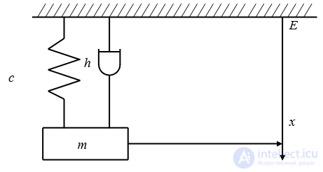
Figure 1. - Schematic diagram of a seismic system with one degree of freedom
Absolute vibration-to-electrical-signal transducers are divided into two classes: generator type, which converts the energy of mechanical oscillations into electrical energy; and parametric type, which converts mechanical oscillations into changes in the parameters of electrical circuits, for example, inductance, capacitance, resistance, frequency, or phase shift, etc.
For vibration diagnostics of machines and mechanisms, mainly piezoelectric and electrodynamic transducers are used, which belong to the generator type, as well as inductive, eddy-current, and capacitive transducers, which belong to the parametric type.
The advantages of electrodynamic vibration sensors include a wide amplitude range, low output resistance, and the ability to transmit signals over a long communication line.
Noise measurement. Acoustic noise is a random process. In the simplest case, the total sound pressure level of the acoustic noise is measured. Measuring microphones are used to measure acoustic noise. The most widely used measuring microphones are of the capacitor, piezoelectric, and electrodynamic systems. Microphones are used with the free sound field method to measure the noise of electrical machines and transformers. In this case, the microphone is positioned at a control point in the field or at points in the field evenly distributed over the measurement surface. Control of the sound field is carried out by measuring the dependence of sound pressure on the distance to the acoustic center of the source and comparing the measured dependence with the theoretical one.
Main diagnostic parameters of electrical equipment. The diagnostic parameters of electrical equipment are:
- electrical parameters: deviations of currents and voltages from nominal values (in amplitude, frequency, phase), the appearance of various types of distortions and losses;
- parameters of thermal processes accompanying electromagnetic processes during disruptions of normal operating modes and aging of structural materials (temperatures in the rotor slots, stator bars, brush-contact assembly, temperatures of cooling and insulating media, etc.);
- parameters of chemical processes occurring in cooling and insulating media (presence of impurities in water, oil, gas, and moisture in transformer oil and insulation);
- light effects caused by electromagnetic effects (glow of high-voltage devices);
- noise parameters (vibrations, etc.) accompanying the operation of electrical devices (generators, motors, transformers).
For diagnosing high-voltage equipment, non-contact remote measurement methods (thermal imaging, optical, etc.) are recommended.
Chromatographic analysis of dissolved gases is a globally recognized, cost-effective, and highly effective method of preventing damage to oil-filled electrical equipment. Monitoring of dissolved gases is a mandatory part of most condition-based maintenance programs.
The main types of electrical equipment are generators, motors, transformers, and grid equipment. The methods and tools of diagnostics discussed below are oriented toward this equipment, but can also be applied to other units and devices operating on similar principles of electrical energy conversion.
In the context of modern Russian power engineering, when 40 - 50% of the main power equipment has reached its design service life, the main task of diagnostics (besides preventing accidents) becomes extending the service life of the equipment up to the full exhaustion of its actual resource. In this case, diagnostic methods that provide monitoring of the current condition of equipment at its installation site, under operating voltage, and preferably during normal operation, come to the forefront. The main question that the diagnostic system must answer is whether or not further safe operation of the equipment is possible.
Maintenance and repair costs are one of the most important operational indicators of any technical system. Minimizing them in cases where the system is repairable is practically impossible without effective monitoring of the system's condition. The service life of technical objects is an important technical and economic characteristic. In fact, the service life should be consistent with optimal values of the service life. Unfortunately, in most industries, the assigned service life does not reach values that are optimal from an economic point of view, and for a number of products, the average actual service life turns out to be less than the assigned one.
Increasing service life represents a serious reserve for saving funds, materials, energy, and labor costs. Thus, increasing the service life of a certain fleet of equipment by an average of 10% is roughly equivalent to a 10% saving in the production of new equipment or the introduction of corresponding new production capacities. Service life largely depends on the modes and conditions of equipment operation. Since predicting service life involves establishing its dependence on all external and internal factors, the development of prediction methods should be considered one of the integral parts of the overall service life problem.
A special place is occupied by service life prediction at the operational stage. Unlike the design stage, when the service life of the general population of technical objects not yet created is subject to prediction, prediction at the operational stage is performed for specific, existing objects. In this case, the remaining service life and (or) remaining service term are subject to assessment.
Review Questions
1. What is technical diagnostics?
2. How does a serviceable technical condition of equipment differ from an operable technical condition of equipment?
3. Give a definition of a diagnostic system.
4 . What is the difference between test diagnostics and functional diagnostics?
5. How are magnetic field transducers classified according to the method of detecting changes in magnetic field parameters?
6. List the diagnostic parameters of vibration.
7. How does the kinematic method of measuring diagnostic parameters differ from the dynamic method?
8. List the main diagnostic parameters of electrical equipment and name the methods by which they are measured.
9. What are the sources of the economic effect from the application of diagnostic systems?

Comments