
Lecture
Это окончание невероятной информации про диагностика ибп.
...
data-auto-open loading="lazy" alt="General Questions on Repairing Uninterruptible Power Supplies (UPS)" >
Transformer fault and diagnostics
To test transformers, they should first be desoldered. They are checked for shorted turns, winding open circuits, and loss or change of the core's magnetic properties.
To check a transformer for a winding open circuit, a simple multimeter is enough; the other transformer faults are much harder to determine, and we will not consider them here. Sometimes a shorted (punctured) transformer can be identified visually.
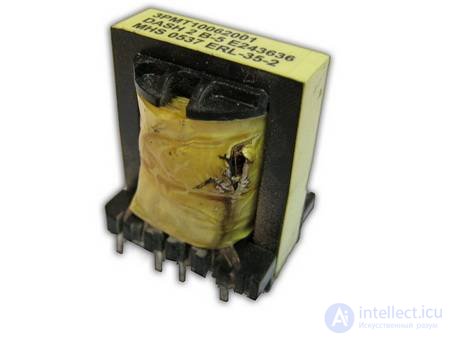
Experience shows that transformers fail extremely rarely, so they should be checked last.
The diodes used in this class of UPS can be conditionally divided into:
Low-frequency rectifier diodes for the input rectifier bridge are selected during replacement based on the following main parameters:
For power rectifier high-frequency diodes, an important parameter is also the reverse recovery time of the diode trr, which determines the duration of the "shoot-through current" mode in the rectifier circuit. This increases switching losses not only in the rectifier diodes but also in the inverter transistors. In this case, the elements of the source end up in a short-circuit mode, which creates conditions for switching spikes on the switching edges, leading to failure of the source. The trr time should be three to four times shorter than the transistor turn-off time and should correspond to trr = 0.3 - 0.5µs. The second important parameter of these diodes is the forward voltage drop Ufwd., on whose value the rectifier efficiency depends. This voltage should be as low as possible.
A relatively lower value of Ufwd is obtained with Schottky barrier diodes. For this type of diode, Ufwd is 0.4-0.6V at currents up to 100A, and the recovery time is no more than 0.1us. The drawback of the diode is a large reverse current and a low permissible reverse voltage (20 - 40V).
For the remaining diodes, the determining parameter is trr.
Powerful rectifier diodes in the +5V and +12V generation channels are mounted on heatsinks, i.e. to ensure the proper thermal operating conditions of these diodes, good heat dissipation must be provided!
A characteristic mistake made by repair technicians when replacing failed imported diodes is not knowing one characteristic feature. Historically, on diodes manufactured by domestic industry the mark is usually applied on the anode side. Imported diodes, as a rule, have the mark at the cathode.
Therefore a repair technician, removing a faulty diode from the board, installs a domestically produced diode in its place, trying to preserve the position of the mark.
As a result the diode ends up soldered in "backwards", which leads to the UPS failing.
However, it must be noted that for both imported and domestic diodes the position of the marks can also be the opposite.
Therefore, before installing a diode on the board it is necessary to determine the lead arrangement using an ohmmeter, without trusting reference books, in which annoying errors are sometimes found! Sometimes marking errors on diodes are made at the manufacturing plant.
Diode faults encountered in practice can be divided into:
All these faults are easily detected using an ohmmeter after desoldering the diode from the circuit.
We draw your attention to the fact that sometimes diode leakage only shows up under voltage!
Major difficulties arise when zener diodes and thyristors fail in the UPS, which are usually threshold and executive elements of various protection circuits.
Determining their types and parameters is often difficult due to the lack of reference information and schematic diagrams for the UPS.
Random selection of these elements risks causing failure of UPS elements that have not yet "burned out". Therefore, in such complex cases it is necessary to "trace" the schematic diagram from the UPS printed circuit board and carefully analyze its operating principle, after which try to select an element with similar parameters, or try to obtain a similar imported element.
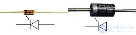
Diodes and zener diodes are checked by continuity testing in both directions. If they read continuity in both directions as a short or an open, they are faulty. Burnt-out diodes should be replaced with identical or similar ones by characteristics, paying attention to voltage, current, and operating frequency.
Diode bridge.
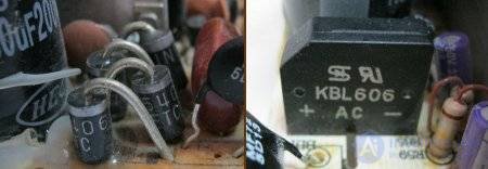
A diode bridge is a diode assembly or 4 diodes standing next to each other. A diode bridge can be checked without desoldering, by testing each diode in the forward and reverse directions. In the forward direction the current drop should be about 500mA, and in the reverse direction it should read as an open.
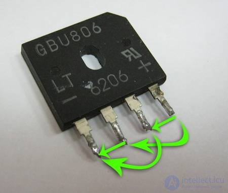
Diode assemblies are measured as follows. Place the negative probe of the multimeter on the assembly pin marked «+», and use the positive probe to test in the directions indicated in the picture.
Transistors used in this class of UPS can be conditionally divided into:
Power high-frequency transistors are used as switches of the half-bridge inverter and are designed to work with significant currents and voltages.
Signal transistors are used in all other functional units of the UPS circuit.
In all circuits of this class of UPS, only bipolar transistors of reverse conductivity type (n-p-n) are used exclusively as power switches.
As signal transistors, both forward (p-n-p) and reverse conductivity type transistors are used. When replacing signal transistors, one should take into account not only the numeric designation of the transistors, but also the letter designations printed on the case. Transistors with different letter designations have different parameters (above all - the current gain)!
Transistor faults encountered in practice can be divided into:
All these faults are easily detected using an ohmmeter after desoldering the transistor from the circuit, since each of the transistor's junctions is similar to a diode.
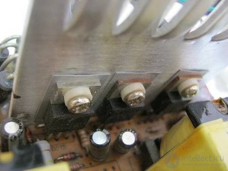
Transistors and diode assemblies that are mounted on a heatsink are most conveniently desoldered together with the heatsink. In the "primary" side there are power transistors, one of which is responsible for standby voltage, while the others form the 12V and 3.3V operating voltages. On the secondary side, on the heatsink, are the rectifier diodes for the output voltages (Schottky diodes).
Checking transistors consists of "testing" the p-n junctions; the resistance between the case and the heatsink should also be checked. Transistors must not short to the heatsink. Checking the diode bridge: If it is made as a separate assembly, it just needs to be carefully desoldered and the now-separated circuit tested on the printed circuit board. If the rectifier is made from individual diodes, it is quite possible to check it without desoldering all of them from the board. It is enough to test each of them for a short circuit in both directions, and only desolder those suspected of being faulty. A good diode should have a forward resistance of about 600 Ohm and a reverse resistance of around 1.3 MOhm.
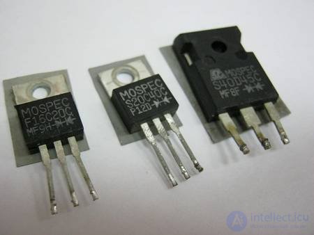
If all the transistors and diode assemblies turn out to be good, do not rush to solder the heatsinks back on, as they hinder access to other components.

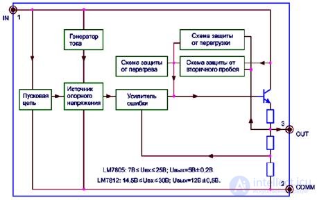
Fig.15. Integrated linear voltage regulators LM7805, LM7812.
These chips contain built-in overcurrent protection and thermal protection against the maximum permissible die temperature (175°C), which significantly increases the reliability of the chips.
A typical connection diagram for these regulators is shown in fig.17.
Capacitor C1 is a standard filter capacitor, which should have a capacitance of 1000uF per 1A of load current.
Capacitor C4 is used to smooth out transient processes during sudden increases in current draw and should have a capacitance of approximately 100uF per 1A of load current.
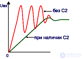
Fig.16. The 7805 IC reaching regulation mode when input voltage is applied.
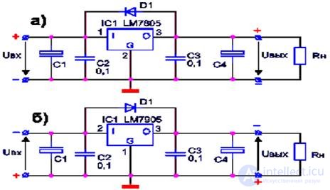
Fig.17. Typical connection diagrams for three-terminal integrated regulators of positive (a) and negative (b) voltages.
In this class of UPS, three-terminal integrated voltage regulators of type 7905, 7912 or 7805, 7812 are mainly used to stabilize the negative output voltages.
The block diagram of the three-terminal integrated regulators 7805 (K142EN5A) and 7812 (K142EN8B) is shown in fig.14.
The main parameters of these voltage regulators are given in table 6.
The input capacitor C2 eliminates oscillation during a step change in input voltage (Uin), which occurs in the regulator due to the effect of parasitic wiring capacitance and inductance of the connecting wires, forming a parasitic resonant circuit (fig.15),
The output capacitor C3 serves to protect against transient interference pulses.
Normally C2 and C3 have a capacitance of 0.1 to 1uF and should be mounted as close as possible to the regulator's case. The amplitude of high-frequency oscillations can exceed the maximum permissible input voltage, which leads to breakdown of the chip, so the presence and good condition of C2 is a mandatory condition for the circuit to work.
Sometimes a diode is connected between the input and output of the integrated regulator (fig.16). Without it, after the UPS is switched off from the mains, the capacitor at the output of the regulator would discharge through the regulator, which could cause it to fail.
The minimum input voltage of the integrated regulator must exceed the output by 2.5V, i.e. for a regulator with a fixed output voltage of +5V, for example, the minimum input voltage is +7.5V.
The pinout of the cases of the integrated regulators of these series is shown in fig.80.
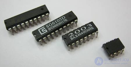
If the PWM chip is not visibly damaged and does not get hot, it is quite difficult to check it without an oscilloscope.
A simple way to check the PWM chip is to check the control pins and power pins for breakdown.
For this we will need a multimeter and a datasheet for the PWM chip. PWM diagnostics should be carried out after first desoldering it. The check is performed by testing continuity of the following pins relative to ground (GND): V3.3, V5, V12, VCC, OPP. If the resistance between one of these pins and ground is extremely low, down to tens of Ohms, then the PWM chip needs to be replaced.
Method for checking the internal regulator: The essence of the method is to check the chip's internal regulator. This method works for the tl494 model and its full equivalents. With the power supply disconnected from the mains, a DC voltage of +9 to +12 volts must be applied to pin 12 of the chip, with the "minus" connected to pin 7, after which the voltage on pin 14 must be measured - it should equal 5 volts. If the voltage deviates significantly (±0.5 V), this indicates a fault in the chip's internal regulator. It is better to buy a new one for this component.
Regarding repair of the standby power supply, it is difficult to advise anything specific - practically anything could burn out, but this is offset by the fairly simple design of this part. It will be quite enough to search through forums on this topic to find the cause of the fault and the method for fixing it.
Часть 1 General Questions on Repairing Uninterruptible Power Supplies (UPS)
Часть 2 9.4 Diagnosing and testing diodes and Zener diodes - General

Comments