
Lecture
Это окончание невероятной информации про микроволновая печь.
...
mechanical pulse generators are sometimes placed there. These devices allow reducing the time needed to enter information and reducing the number of buttons on the keyboard. The operating principle and design of the pulse generator are very simple and are explained in fig. 2.31.
When the generator knob is turned through some angle f, bracket 1, mounted on the same shaft, also turns. The bracket has two pairs of contact blades 2. The blades of the first pair alternately close against fan-shaped metal strips 3, which are electrically connected to each other. These strips can be made directly on the board by an etching process. The second pair of blades provides sliding permanent contact with the generator's output terminals. If the connection scheme of the mechanical pulse generator corresponds to the one shown in the figure, then the alternating closing and opening of the contact between the blades and the strips, as the knob is turned, produces pulses at its output. The blades of the first pair are slightly offset from one another, so the output pulses at the outputs are spaced apart in time. This allows the microcontroller to determine the direction of the knob's rotation, which is necessary if the same generator is used both for increasing the indicator's readings and for decreasing them.
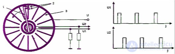
Fig. 2.31. Design of a mechanical pulse generator

Fig. 2.32. A button variant for a microwave oven control unit
Sometimes a type of keyboard is found in which the buttons are made using planar technology, as shown in fig. 2.32.
When a button is pressed, the contacts to be closed are pressed together by a cylinder of conductive rubber, ensuring their closure. The resistance of such a contact can be hundreds of ohms, however this is enough for the microcontroller to distinguish the closed state from the open one. However, over time the resistance can significantly increase for various reasons, and mutual understanding with the controller is lost. This can be fixed by gluing a piece of foil onto the contact surface.
Display
Character-forming displays serve to display information entered from the keyboard and the current operating status of the microwave oven. They convert electrical signals into a visible image of digits, letters, etc. The most widespread are displays based on such physical effects as: cathodoluminescence (in vacuum fluorescent displays), electro-optical effects in liquid crystals (in liquid-crystal displays), and injection electroluminescence in p-n junctions (in semiconductor displays).
By the way information is displayed, displays can be divided into segment and matrix types. In the first case, the display elements are made in the form of segments, from which digits or letters can be composed. A typical representative of this family is the eight-segment display shown in fig. 2.33a. It allows displaying all digits and a limited number of letters.
A matrix display is a set of elements in the form of dots, grouped into rows and columns (fig. 2.33b). With its help, digits, any letters of both the Latin alphabet and Cyrillic, as well as various signs and pictograms, can be displayed.
Displays can be multi-digit, having several character positions in a single housing (fig. 2.33c). If a display is specifically designed for use in a microwave oven control unit, it may contain specific mnemonic diagrams displaying the current operating mode.
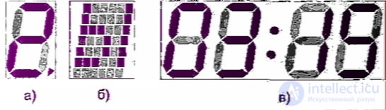
Fig. 2.33. Eight-segment (a), matrix (b) and multi-digit (c) displays
There are two basic connection schemes for character-forming displays: static and multiplexed. In static mode of operation, all display elements (segments, dots, etc.) have separate leads. Control signals are applied simultaneously to all elements participating in the display of information.
In multiplexed mode, the display elements do not have independent leads. Identical elements of all character positions (or elements of one row in a matrix display) are connected to a separate common supply bus. Voltage is applied to these buses sequentially in time. At any given moment, only one bus is energized. The character positions (columns in a matrix display) have independent control circuit leads. If a constant control signal is applied to a given character position, then all elements of that character position will be lit in turn. In order for the desired set of segments to be displayed, the control signal is applied only at those moments when supply voltage is applied to the buses corresponding to those segments. In doing so, some flicker of the display elements may be observed, since their on-time is relatively small compared to the period between activations. So that this does not irritate the eyes, the frequency of supply pulses applied to the buses should be more than 40 Hz. In this case, the human eye does not notice flicker, even if it is present. As an illustrative example, fig. 2.34 shows a typical display for a microwave oven and the timing diagrams of the signals at all leads when displaying the word End, signaling the end of operation.
The advantage of the multiplexed mode is that it allows the number of indicator leads to be significantly reduced. For example, for normal operation of the semiconductor matrix indicator in Fig. 2.336 in static mode, 43 leads are required, while in multiplexed mode only 13.
Let us examine in more detail the design and main features of the indicators used in microwave ovens.
The vacuum fluorescent indicator (Fig. 2.35) is a tube triode enclosed in a flat glass housing from which the air has been evacuated. The anodes are made in the form of segments coated with cathodoluminescent phosphor, which glow under electron bombardment. Depending on the composition of the phosphor used, the segments may have different glow colors. The anode voltage of most indicators is 27–30 V.
The directly-heated cathode is made of several filaments of thin oxide-coated tungsten wire secured on tension supports. The heater is usually powered by an alternating voltage of 2.4 V. The service life of the vacuum fluorescent indicator is largely determined by the durability of the oxide cathode. The operating temperature of the cathode, corresponding to the rated heater voltage, is chosen so as to ensure its maximum durability. An elevated heater voltage accelerates the evaporation of the emission-active layer, while a reduced voltage weakens the cathode's resistance to factors that degrade the oxide coating. If the heater voltage deviates from the rated value by 10%, the service life of the indicator is reduced by roughly an order of magnitude.
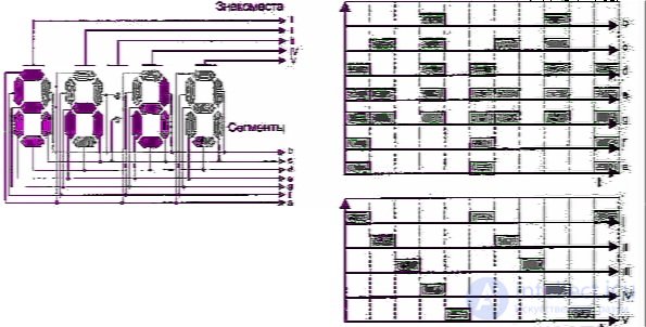
Fig. 2.34– Operation of a multi-digit indicator in multiplexed mode
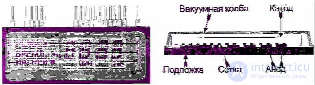
Fig. 2.35– Vacuum fluorescent indicator for a microwave oven
The grid is made of tungsten, has a fine structure and high transparency to electrons. To fully suppress the glow of the anode segments, a blocking (negative) voltage of 1.5 to 5 V must be applied to the grid.
Liquid crystal indicators are passive. They do not emit light themselves, so a source of transmitted or reflected light is required for them to work. Liquid crystals are organic compounds that exist in an intermediate state between solid (crystalline) and isotropic-liquid. Under the influence of an electric field, the molecules of the liquid crystal reorient themselves, which changes its transparency. Fig. 2.36 shows the design of a liquid crystal indicator operating in reflected light. A liquid-crystal substance 2 is placed between two transparent glass plates 1. Electrodes made of a transparent electrically conductive film 3 (for example, tin dioxide), shaped as segments of the required form, are deposited on the inner surface of the top (front) plate. The bottom electrode 4 has a high reflectance and is common to each digit position. The distance between the plates is 5–20 µm.
If voltage is applied to any segment, the intensity of the reflected light passing through the liquid-crystal substance decreases significantly, causing that segment to appear darker. In the absence of voltage, light is reflected almost unimpeded from the mirror surface of the bottom plate.
The advantage of liquid crystal indicators is their very low power consumption; the drawback is low contrast, especially in low light. This drawback is absent in indicators that operate in transmitted light. The difference of such indicators from the one described above is that the common electrode is also transparent, and an internal light source is located behind the bottom plate. In addition, there are liquid crystal indicators based on other physical effects, which in particular allow color images to be obtained. However, at present all these varieties of indicators for microwave ovens can be regarded as a rare exotic case.
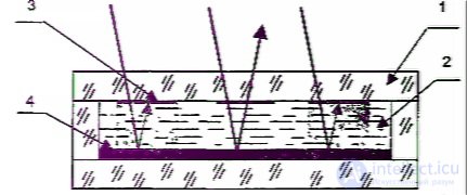
Fig. 2.36. Principle of operation and design of a liquid crystal indicator
The service life of liquid crystal indicators is limited by the fact that over time the contrast between active and passive zones deteriorates, the orientation of the molecules is disturbed, and the switching time increases. This is related to electrochemical phenomena at the liquid crystal — substrate boundary. The rate of degradation processes is related to the presence of a DC component in the excitation voltage, which leads to electrolysis in the liquid crystal and gas evolution. The electrodes lose their transparency, and the segments become visible in the absence of excitation voltage, the seal is broken, and the current consumption increases.
Semiconductor indicators are a set of LEDs made in the form of segments located on a common substrate. LED emission occurs in the region of the p-n junction when direct current is passed through it. In this process, excitation of atoms occurs, i.e. electrons are pumped to higher energy levels. This state of the atoms is unstable, so they tend to return to their original position. During the return process, the additional energy received during excitation is released in the form of photons, which produces the glow. LED emission occurs in the visible and infrared wavelength ranges. Semiconductors that emit energy in the infrared range are sometimes coated with a phosphor that converts the invisible radiation into visible radiation.
The advantages of semiconductor indicators include low supply voltage, compatibility with integrated circuits, high speed, mechanical strength, reliability and durability. The drawbacks include high current consumption and high cost.
As a rule, indicators for microwave ovens are not repairable. There is nothing particularly wrong with using an indicator of a different type when replacing one, as long as it is based on the same operating principle. However, this will require some rework of the circuit board, since the leads of different types of indicators usually do not match.
Thyristors and triacs
A thyristor is a switch-type semiconductor device that conducts current in one direction. It has three electrodes: anode, cathode, and gate electrode. The appearance of thyristors and triacs is shown in Fig. 2.37.
The anode of the thyristor is electrically connected to the device case. The family of current-voltage characteristics of the thyristor is shown in Fig. 2.38. The forward branches of each of the characteristics have three sections. The first, from the origin to point A, is a high-resistance section similar to
the reverse branch of an ordinary rectifier diode. In this state the thyristor is off, and virtually no current flows through it. The second section, between points A and B, corresponds to an unstable state in which the thyristor, even at a slight excess of the so-called switching voltage Uswitch, transitions into a low-resistance state (point B). This section is characterized by negative differential resistance: an increase in current in this section is accompanied by a decrease in the voltage between cathode and anode. The section from point B onward is characterized by high conductivity or low resistance and is similar to the forward branch of a semiconductor diode.
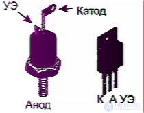
Fig. 2.37. Appearance of the packages for thyristors and triacs used in microwave ovens
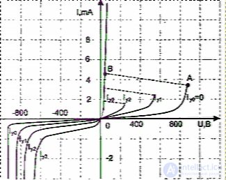
Fig. 2.38. Current-voltage characteristics of thyristors
If a gate current Ig is passed through the gate circuitgate, the switching voltage decreases. By gradually increasing Ig, we reach the latching current at which the negative-resistance section disappears entirely.
In practice, the operating voltage is chosen lower than the maximum switching voltage, which is reached at Ig=0, so in the absence of gate current the thyristor is in the off state. In turn, the gate current is usually chosen to be greater than the latching current, so that when gate current is present the thyristor always has low resistance regardless of the anode voltage.
A notable feature of the thyristor is that once switched into the high-conductivity state, it will remain in that state indefinitely even after the gate signal is removed. This property allows the thyristor to be turned on using short pulses of gate current. To turn the thyristor off, it is necessary to reduce the current in the anode circuit, by lowering the anode voltage, down to a certain small value on the order of the latching current, called the holding current. If the thyristor is placed in an AC circuit, it turns off automatically at the moment the voltage passes through zero.
The reverse branch of the thyristor's current-voltage characteristic, in the absence of gate current, is similar to the corresponding characteristic of a diode. The appearance of gate current causes a slight increase in the reverse current of the thyristor. In general, it can be assumed that with negative voltage on the anode, no current flows through the thyristor regardless of the state of the gate electrode.
Thyristors are used mainly as electronic switches and power regulators. They are able to switch, virtually without losses, circuits carrying currents of tens or even hundreds of amperes. However, thyristors have one significant inconvenience — they conduct current in only one direction, which limits their use in AC circuits.
This drawback is eliminated in triacs. The Russian name for the triac ("simistor") comes from combining the words "symmetrical thyristor." Some people in the West call the simistor a triac. Sometimes this term is used in our technical literature as well. To avoid confusion, we will consider "triac" to be a synonym for "simistor."
A triac is capable of conducting current in both directions. Switching from the closed state to the open state occurs when a voltage is applied to the gate electrode. To close the triac again, it is necessary to change the polarity of the voltage on the main electrodes. This is not a problem, since the triac is designed to work in AC circuits, where this happens automatically every half-cycle.
Structurally, triacs are manufactured in the same packages as thyristors. Therefore, by analogy, the main electrodes of triacs are sometimes called the anode and cathode. In fact, the concepts of anode and cathode lose their meaning for a triac, since its main electrodes are equivalent. There are special names for the main electrodes of a triac used in technical literature — the power electrode on the gate electrode side, abbreviated as MT2 (gate-side main terminal), and the power electrode on the device base side — MT1. However, the Russian language rejects such long and elaborate names, so in everyday use the terms anode and cathode are still used.
The current-voltage characteristics of a triac are shown in fig. 2.39.
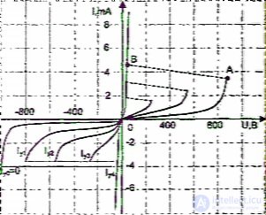
Fig. 2.39. Current-voltage characteristics of triacs
Unlike a thyristor, the reverse branch of a triac's characteristic resembles the forward branch. But it only resembles it, rather than being its mirror image. A triac cannot be regarded as two thyristors connected back-to-back in one package. Otherwise, it would be necessary to have two independent gate electrodes, which would noticeably complicate the control circuit. Turning on the triac in an arbitrary direction is done from a single signal source. Moreover, the control signal can be either bipolar, when the polarity between the cathode and the gate electrode corresponds to the polarity between the cathode and the anode, or unipolar, when, regardless of the polarity of the voltage between the anode and cathode, a potential negative relative to the cathode is applied to the gate electrode. The first option is preferable in terms of triac parameters, but in a number of cases it is simpler to use the second option.
The main differences between the forward and reverse branches of the triac's current-voltage characteristics are that the switching voltage and the latching current for the forward branch are lower than the corresponding parameters of the reverse branch. From this, the following practical conclusions can be drawn: if the voltage between the anode and cathode is greater than the switching voltage of the forward branch and less than the switching voltage of the reverse branch, then the triac will begin to conduct current in one direction, i.e., it will operate as a rectifier diode. A similar situation will arise if the voltage on the device in both cases is less than the switching voltage, but there is a signal on the gate electrode that allows the triac to be turned on only in the forward direction. Since the parameters of semiconductor devices depend noticeably on the operating temperature, when selecting a triac it is necessary that the operating voltage differ from the switching voltage with a margin. The same applies to the control current: it must be reliably greater than the latching current.
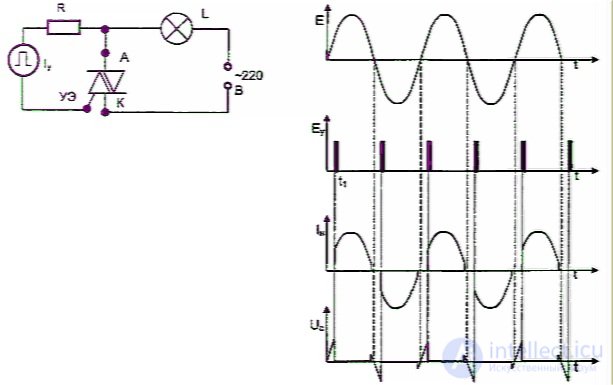
Fig. 2.40. Circuit for connecting a triac into an AC circuit and the corresponding oscillograms of currents and voltages
A typical circuit for connecting a triac into an AC circuit and the corresponding oscillograms of currents and voltages are shown in fig. 2.40. An ordinary incandescent lamp is used as the load in the circuit. The source of anode voltage is the household electrical mains, and negative-polarity pulses from a special generator are applied to the gate electrode.
At moments in time t±nn, the control pulses trigger the triac, its resistance drops sharply and current begins to flow through it. The voltage across the triac at this moment drops to approximately 1 V. This state continues until the alternating current passing through the triac becomes less than the holding current. At this moment the triac turns off and remains in this state until the next control pulse arrives. After that, everything repeats, but with reversed polarity of currents and voltages. In principle, the control signal does not necessarily have to be pulsed. It can also be constant. In this case, the triac turns on when the anode current exceeds the latching current. This increases the current consumed by the control circuit, but, as a rule, it is incomparable with the current of the anode circuit, and this factor can be neglected.
The advantage of pulsed control is that it makes it possible to regulate the output power. If the moment of applying control pulses is delayed by some time relative to the beginning of the half-cycle, the RMS value of the voltage applied to the load will decrease (fig. 2.41). Thus, by changing the delay time of the control pulses, it is possible to regulate the power in the load from a maximum value down to zero.
In microwave ovens, the phase power control principle discussed above is generally not used. However, it is used in special mains adapters that allow devices designed to work with a lower voltage to be plugged into a 220 V mains supply. In particular, in many countries of the world (for example, in the USA), the standard household mains voltage is 110 V, so all household electrical appliances purchased there and plugged in here will all behave the same way: like a fireworks display. To prevent this from happening, the above-mentioned adapters are used. They are compact devices, resembling in appearance an electrical splitter plug inserted into an outlet, and are packed with a triac and its control circuit.
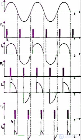
Fig. 2.41. Shape of the load current as a function of the time at which the pulse is applied to the triac's gate electrode
In microwave ovens, the load is always connected through a transformer, which, in particular, can operate in saturation mode (fig. 2.42). In this case the current curve will differ somewhat from the one shown above.
First, the current envelope will change its shape. From sinusoidal it will become flatter, limited by the saturation current. In addition, with an inductive load, the current lags the voltage in phase by an angle ph, approximately equal to pi/2. The value of this angle depends on the ratio between the active and reactive components of the load impedance. As a result, the control pulses must be shifted by the same angle. To ensure reliable turn-on in systems with inductive loads, wide control pulses or bursts of narrow pulses are most often used.
As established earlier, an incorrect choice of mode can lead to the triac operating only during positive half-cycles. In the case of a resistive load, this usually does not entail any particular consequences. However, with an inductive load, this is fraught with major problems. The load current will contain a DC component, for which the inductance offers practically no resistance. As a result, if a microwave oven transformer is used as the load, its primary winding will overheat severely, and vouching for its continued serviceability would border on irresponsibility. In Lena-type microwave ovens, this is the main cause of failure of filament transformers. Moreover, the most unpleasant aspect of this situation is that the process can begin spontaneously, at a moment when the oven is not operating but is connected to the mains.
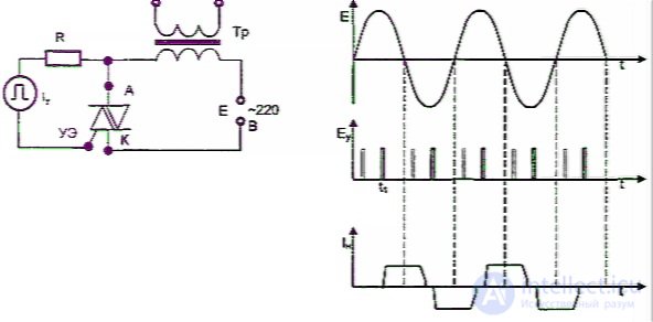
Fig. 2.42. Features of connecting a microwave oven transformer through a triac
c)
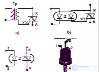
Fig. 2.43. Options for electrical isolation of the power and control circuits when using a triac
A possible cause of incorrect triac operation may be the failure of one of the arms of the diode bridge that supplies the control circuit. In this case, during one of the half-cycles, the control signal is either completely absent or turns on the triac with a delay, which leads to asymmetric operation of the latter and, as a result, to the appearance of a DC component of current with all its consequences.
In some cases, in order to provide good isolation between the anode and control circuits, the gate electrode is connected to the circuit through a pulse transformer or an optocoupler pair (fig. 2.43a, b). In the latter variant, the triac is triggered by the electromotive force arising at the photodiode's electrodes when it is illuminated by an LED. However, this —
circuit will only work at small control currents. The situation is simplified if an optotriac is used as the switching element (fig. 2.43c). Its difference from an ordinary triac is that it has no gate electrode, and is switched into the conducting state by the photoelectric effect when the p-n junctions are illuminated by an LED built into the package. Therefore, the anode circuit of the optotriac is completely isolated from the control circuit.
Microcontrollers
A controller is the term commonly used for a specialized microcomputer designed for controlling specific devices. The set of functions of a controller is usually limited to the framework of the tasks that need to be solved with the help of these devices. If all the main elements of a controller are located on a single chip, it can confidently be called a microcontroller (fig. 2.44).
With the advent of microcontrollers, digital and digital-analog circuit design entered a qualitatively new stage of its development. The task of any electronic circuit is to generate the required output signals depending on the input signals. Previously, solving this task in many cases required the creation of complex electronic circuits consisting of flip-flops, logic elements, decoders, and so on. At the same time, even a small change in the circuit's functions sometimes required substantial rework of it. A microcontroller allows the same range of tasks to be solved by software means. In this case, the relationship between the input and output signals is determined by the program's text, which, if desired, can be quite easily changed. Thus, one and the same circuit can be used both for controlling a microwave oven and for regulating fuel consumption in a car.
The scope of application of microcontrollers is constantly expanding. This is due to the fact that they offer extensive capabilities at a relatively low cost. Currently, hundreds of millions of microcontrollers for various purposes are sold worldwide every year. Practically all household electrical appliances have models with built-in microcontrollers. Some microchips sometimes include a miniature lithium battery, and thus it becomes possible to use microcontrollers in items that are related to electricity in roughly the same way a pickled cucumber is related to the Pythagorean theorem. Examples include various smart cards, self-guided aerial bombs, and musical greeting cards. It seems the day is not far off when nails and toilet paper will come equipped with microcontrollers.
The control units of microwave ovens use the simplest 8-bit controllers. As a rule, they belong to the category of custom-order chips and have one-time programmable memory, i.e., the microcontrollers in question are intended to work exclusively in a specific device and cannot be replaced with anything else. The custom-order nature of the microcontroller means that the consumer company orders it from the manufacturer for its own specific design. As a result, due to limited demand for these products, they are practically absent from open retail sale. Therefore, if the microcontroller has failed, it is pointless to look for a replacement in an electronics store. The only place where it can be found is the service and repair department of the company that manufactured the given appliance. The goals and scope of this article do not allow us to dwell in detail on the design and operation of each member of the numerous family of microcontrollers. (For reference: Motorola alone produces more than 300 part designations.) Therefore, we will only consider general questions that will allow some orientation in this matter, while specific recipes are given directly in the descriptions of the operation of certain control units.
A microcontroller includes the following basic elements: a microprocessor, random access memory (RAM), read-only memory (ROM), and input/output ports. Additionally, controllers can be equipped with various timers, analog-to-digital converters, and so on, depending on their field of application. A block diagram of a typical controller is shown in fig. 2.45.
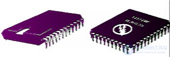
Fig. 2.44. External view of some microcontrollers
The main element of a microcontroller is the processor. It synchronizes the operation of all other devices and monitors their activity. In addition, inside the processor there is an arithmetic logic unit (ALU), which can conditionally be thought of as a built-in calculator. During operation, the processor sequentially reads information from memory, recognizes the instructions stored there, and either executes them itself, for example when calculations are required, or delegates the task to its counterparts.
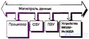
Fig. 2.45. Controller block diagram
The sequence of the processor's actions is set by a program stored in ROM. Normally, the program is written during the manufacture of the microcontroller and cannot be changed afterward. The size of the read-only memory is usually a few to several dozen kilobytes. (One byte of information allows storing any digit, letter of the Cyrillic or Latin alphabet, mathematical and some other symbols, 256 characters in total, which is why it is adopted as the unit of measurement.)
Data entered by the user (operating time, mode, etc.) and the results of the processor's intermediate calculations are stored in RAM. Information stored in RAM can be read by the processor or changed at any moment. When power is switched off, the information is lost, unlike ROM, where it is stored permanently. The amount of RAM in microcontrollers is small and amounts to only a few hundred bytes.
The input/output ports serve to connect the microcontroller with the outside world. They provide input of information from the keyboard, its display on an indicator, and the output of control signals to actuating devices such as relays, triacs, sound buzzers, and so on. To match power levels, the port outputs are sometimes connected to actuating devices through buffer amplifiers.
Some ovens have various types of sensors (temperature, empty cavity, weight, humidity, etc.) that have an analog signal at the output. To convert these signals into a digital code understandable to the microcontroller, an analog-to-digital converter (ADC) built into it is used. If the oven has several sensors at once, the ADC can operate in multiplexed mode, tracking their readings in turn.
Data transfer from one unit to another is carried out over a data bus. The outputs of all microcontroller units have three stable states: logic 0 and 1, as well as a high-impedance state (the so-called Z-state). In the latter case, the unit can be completely electrically disconnected from the data bus. This allows the processor to organize communication between the units in such a way that at any given moment only one output and the required number of inputs are connected to the data bus.
The main question when repairing a microwave oven's control unit is to determine whether the malfunction is related to the operation of the microcontroller, and if so, whether it can be helped. It should be noted that such failures are not common, so before blaming the microcontroller, one must make sure that the problem is not related to simpler things. First of all, it is necessary to make sure that power is present and corresponds to the rated value. It makes sense to examine the printed circuit board for breaks and shorts. The latter are sometimes caused by the digestive byproducts of insects known for their voracity and fertility. A short circuit can also occur in the keyboard. Inability to start may indicate the absence of a door interlock signal.
As already noted, it is practically impossible to find a replacement for a faulty microcontroller. If it has failed, you have two options: throw away the control unit or try—
to repair it. The first is faster. Let us immediately note that with respect to ovens of Russian manufacture (Beregina, Elektronika-25, etc.), in which the controller is built on the basis of a general-purpose single-chip microcomputer with external ROM, this kind of dilemma arises specifically when the ROM is faulty. In some ovens (for example, Gold Star*), a failed microcontroller can sometimes be artificially revived, but this happens relatively rarely. Theoretically, it is possible to install a universal programmable microcontroller in place of the broken one. For this, for example, a programmable single-chip microcomputer of the MK51 family (the Russian equivalent KM1816VE51) may be suitable. The author has, in his own practice, had occasion to perform such a procedure, but it can hardly be recommended for widespread use.
The main problem lies in writing a program that must provide control of all the functions of the microwave oven, taking into account the peculiarities of the existing circuit. Even for a specialist this can take anywhere from a few days to several weeks. Moreover, flashing the chip requires a computer and a programmer. Therefore, we will not dwell on this issue in detail; anyone who feels capable of handling this task will most likely manage without the author's recommendations, and a non-specialist had better not add to their own headaches. It's easier not to get tangled up than to untangle yourself.
When repairing the HV section (magnetron power supply), there is a need to test its components with a continuity tester. A household tester is not effective here, its battery voltage is too low. Some sources recommend checking HV components with a 15-25 W, 220V incandescent test lamp. Testing with it is unsafe from a safety standpoint, and moreover, it does not give a 100% reliable result.
It is safer to make an HV test bench yourself: the input resistance on a tester at the 750 V AC measurement range is several megohms. Touching the blue wire on the diagram will give no more sensation than using a phase indicator probe. It is only necessary to mark the phase on the outlet and connect the red wire's input according to the diagram to the plug.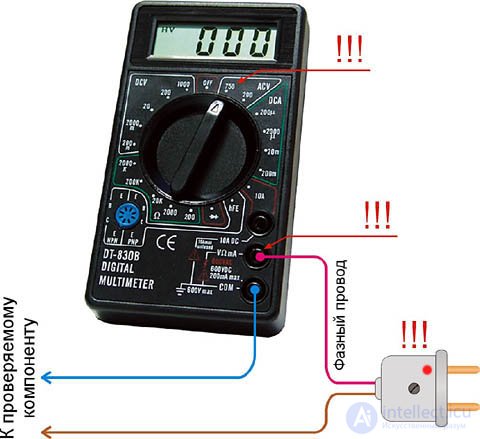
This bench provides a greater sensitivity threshold; with it you can also find components on the verge of failure, which are the cause of periodic malfunctions in the operation of all units:
Remember that manipulations with the component being diagnosed are performed only on the condition that it is completely disconnected from the mains power.
The high-voltage power supply of the magnetron is arranged according to a half-wave voltage-doubler circuit; this is possible due to the pulsed mode of operation. One should not even attempt to make such a supply for household needs, since it is designed to operate under a secondary-winding short circuit for 5 minutes.
The positive half-wave from the secondary transformer winding closes through the high-voltage diode D and charges the high-voltage capacitor C to a level equal to its peak voltage of 2000 V. The negative half-wave, through the same diode, carries out an additional charge up to 4 kV, similar to the voltage-boost circuit of old TVs. The magnetron starts SHF generation with the emitter voltage when C discharges, and the cycle starts anew.
The HV fuse F and discharge resistor R perform a protective function. F shuts off the magnetron if an instantaneous overload occurs along with a temperature rise. For example, if the chamber was not loaded, was overloaded, a metal object was placed in it, or a non-standard product was placed in it. Current flow through R provides quick discharge of the capacitor, this is a protection against radiation leaking outside if the door was opened while the appliance was operating.
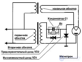
When F burns out in the circuit shown, the radiation flow may escape outside if there is poor shielding or grounding, since an electric arc is still observed for a fraction of a second in the blown fuse. For this reason, some models use a circuit that powers the magnetron through a protective diode, as shown in the picture above. This way surges will not occur, the inconvenience is that the diode is single-use, it burns through often, and its price is comparable to that of a high-voltage capacitor. The diode can be tested on the same test bench, connecting it forward and reverse, the tester will show about half of the mains voltage. When the difference is 20% or more, it is broken, while cranking with an induction megohmmeter and testing with a test lamp will show full serviceability.
All faults of the HV PSU cause it to operate without warm-up. F always burns out. By itself, it is a fusible link, but its filament is spring-loaded so that it opens faster. It is checked with an ordinary tester. The HV capacitor is checked on the test bench, the tester shows 10-70 V on both sides, depending on the capacitance of the part, which is printed on the housing.
Transformer
After testing all 4 HV components, the power supply to the transformer feeding the magnetron is checked. Heating does not occur due to a short circuit between turns in the windings. The tester will show nothing here, because the active resistance of the windings remains unchanged. It is best to check a suspicious transformer at a company specializing in electrical measurements, at a power grid company laboratory or consumer protection laboratory. The cost of this service is low everywhere.
The check can also be done at home. If there is a turn-to-turn short circuit, the no-load current of the transformer increases by orders of magnitude. We allow for a fault, and take that same 220V 15-25 W test lamp. The test bench will not show this: the tester's current in voltmeter mode is small, and an ammeter is dangerous for this operation.
The test lamp is connected in series with the HV winding. Using another winding is very unsafe. It is not hard to find – it is covered with a good layer of insulation together with the filament winding, as can be seen in the illustration.
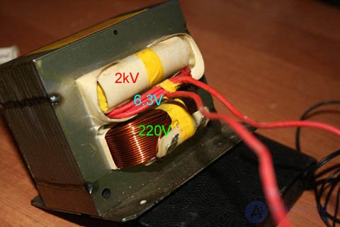
After assembly, the chain is connected to the mains for a few seconds. With a working transformer, the lamp either will not light up, or the filament will warm up barely, to a dull red color. A clearly visible glow indicates the presence of a turn-to-turn short circuit.
Without diagnostic experience, it is hard to say exactly which glow is called dim and which is noticeable. To be sure of the correctness of the diagnosis made, let's arrange an artificial turn short. Disconnect the circuit from the mains, short the filament winding, and turn on the mains again for a short time. The filament in the lamp should light up brighter than the first time. If the glow stayed the same or changed insignificantly – the transformer is faulty.
When all HV components have been checked, and the SHF still did not manifest itself, the magnetron is most likely broken. To avoid dismantling it and the SHF waveguide path, diagnostics can be carried out with a standard tester, which will determine whether there is an internal short circuit in the magnetron. This can happen if the internal surface of the cathode has delaminated.
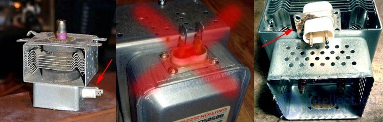
On the same level of frequency as internal short circuits among magnetron faults is breakdown of the cathode filter (red arrow in the right-hand image). It looks like an ordinary connector, but it is actually a pair of high-voltage feedthrough capacitors. Damaging their sealing compound is forbidden – center image. It will give nothing in diagnostics, and the particles are dangerous toxins. The resistance between the leads is measured with a tester. The reading should be close to zero: the leads are powered from the filament, the current is close to 10A at a voltage of 6.3V.
Carefully unscrew the assembly with the feedthrough capacitors, most models allow this to be done without dismantling the magnetron and the SHF waveguide path. The presence of breakdown is visible immediately – right part of the illustration. If nothing is visible, carefully cut the assembly off from the filter inductance and check continuity on all leads on the test bench. A working tester will determine functioning feedthroughs as zero in all cases. If it shows at least two volts – there is a hidden breakdown or leakage under voltage. When everything shows in order, but the temperature in the chamber does not rise – the cathode has suddenly lost emission and the magnetron can be thrown away. This happens with magnetrons, powerful generators, klystrons and traveling wave tubes (TWT) due to loss of housing hermeticity, where there should normally be a full vacuum. The magnets in the magnetron can become demagnetized, in which case the HV fuse burns out immediately upon startup.
We finish the logical chain with the chamber, but it experiences and provokes more faults than other components. A situation like 1 in the illustration is not as catastrophic as it seems at first glance: the chamber has a special coating that withstands such loads. Except in cases when an egg is cooked in it – overboiled denatured protein bakes very firmly into the coating, and the only thing that can help is buying another unit. We clean off debris, wash it with suitable detergents and examine it: check for scratches deeper than 0.1 mm. Now we manually check how smoothly the turntable rotates and test for shielding and "siphoning". There is a very high chance that the microwave will still serve for many more years. In a situation of a coating burned all the way through, as in 2 in the illustration, it cannot be used. No repair can remove the background radiation.

Most often you can observe this picture – the oven works adequately, the load is correct and already checked, sparks are visible. Wash your hands, move the oven to the cleanest and driest possible room, carefully remove the cover of the waveguide output window – when it is possible to remove it from the outside without touching the SHF waveguide path. The material the cover is made of is very fragile. From the outside it is clean or has barely noticeable dirt or damage, from the inside we will see something different – 3 and 4 in the illustration. We see traces of steam from fat and soot.
For replacement, we select an identical part. Some sources may advise making it from 1.5 mm material, which is almost 4 times thicker than the factory one, which is equal to 0.4 mm. If you look into it, mica does not give an ideal transparency rating for SHF, a cover with a thicker rating picks up excess temperature and fat vapors, and its service life is much shorter than the original. The main problem is that the mode will be disrupted and the microwave will start to leak radiation heavily.
In models with a short waveguide path, after removing the cover, we will see the inner part of the waveguide (to be more precise, this is the output resonator) and the antenna (radiator) of the magnetron. When the coating on the resonator is intact, without blisters, cracks and heat-tint colors, it can be cleaned with alcohol using the scheme described above. If the radiator has darkened, it is simply removed from the magnetron and replaced with a new factory one. If the radiator is old and has seized in its socket, it is removed by carefully rocking it with pliers, and the new one is installed only while wearing gloves, without scratches or dirt on it.
We remember three main nuances. You cannot remove the magnetron yourself or try to use a burned-through radiator by turning it to the other side. The oven's mode will be disrupted and it will leak radiation. When the SHF waveguide path was touched, be sure to check the oven for radiation leakage using the method described above after all work is finished.
Часть 1 Diagnostics and Repair of Microwave Ovens
Часть 2 Composition of a microwave oven - Diagnostics and Repair of
Часть 3 High-voltage test bench - Diagnostics and Repair of Microwave Ovens

Comments