
Lecture
Это продолжение увлекательной статьи про микроволновая печь.
...
they will not be used immediately. By the end of the defrosting process, room temperature should be maintained. This will have a good effect on the taste of the product.

The following overview shows which power levels are suitable for particular processes.
|
900 W and above |
– for heating liquids, – starting level for boiling and frying at the beginning of cooking |
|
750 W |
– for cooking vegetables (lower value is preferable) - for cooking food (lower value is preferable) |
|
600 W |
– for defrosting and reheating frozen food - for reheating dishes in pots |
|
500 W |
– for finishing cooking a dish in a pot - for cooking dishes with eggs |
|
450 W |
– for longer cooking of a dish |
|
350 W |
– for cooking delicate dishes - for reheating baby food |
|
250 W |
– for cooking fluffy rice - for melting jelly |
|
150 W |
– for defrosting meat, fish, bread |
|
80 W |
– for defrosting cheese, dairy products, butter - for proofing yeast dough - for preliminary heating of food and drinks |
When the outer casing is removed, a detailed picture of the construction opens up. In newer models – in the image on the right – the assemblies vital for the operation of the appliance: the high-voltage unit, the EMB, and the programmer. All of them are always protected by covers and equipped with a high-voltage fuse, which the first models did not have.
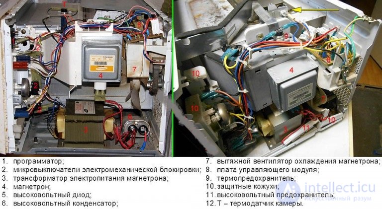
The picture does not show the illuminating lamps, the grill, or the turntable mechanism. To access them, you need to remove the cooking chamber or completely disassemble the oven, which is the case in most new models and in some representatives of previous generations. Doing a self-repair in this situation is more difficult, because even a minor breakdown forces the removal of the magnetron, which is bad in itself. Let's look at this further.
All these parts are used to heat food throughout its entire mass at once using superhigh-frequency radiation – microwaves. It comes from a powerful, compact generator – the magnetron. This video does a good job of describing its design and method of operation:
Into partially electrically conductive media, the radiation penetrates to a depth almost equal to the wavelength; the medium absorbs the waves with the release of heat. Here the wavelength corresponds to a standard frequency of 2.45 GHz, in some cases 2.85 GHz, which determines the maximum absorption of microwaves by the load. We can see the positive properties of microwave heating: because heating occurs across the entire surface at once, the temperature of the food does not reach the thresholds beyond which fat hydrolysis begins, resulting in the formation of toxins and carcinogens. This is very relevant during heating, since if food is heated on an open flame or by a heating element, hydrolysis in it proceeds to other stages, and previously formed products continue to break down, forming more harmful components.
Microwaves do not penetrate metal objects; this is due to the nature of their conductivity – not from free charge carriers, but by means of the so-called degenerate electron gas. This same component gives metal its shiny surface and its ability to be forged. For this reason, metal objects are not used in microwave ovens – all the waves will concentrate on them, causing the surface to overheat, forming arc discharges and other unpleasant effects; after such use, there's no point in repairing the appliance. The only option is to fit the magnetron's power transformer to a homemade spot welder.
But this same reason makes the radiation physiologically harmful to living organisms; it causes significant harm, although this is not immediately apparent. To prevent negative consequences, manufacturers resort to individual safety measures in the design, and certain precautions must be followed both in use and in repair.
The functional diagram of the construction is shown in the illustration. It approximately shows the configuration of the waveguide and the microwave flow; the diagram matching the realities of modern appliances is shown at the bottom right.
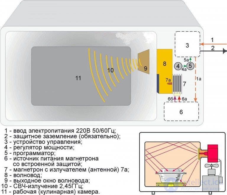
1a – mains current flow at a voltage of 220 V. The power of the magnetron's waves cannot be adjusted smoothly; pulse-width modulation – PWM – is used to reduce and increase it. 4a and 5a – control signals passing inside, 6a – the constant cathode (emitter) voltage of the magnetron, at a high level – 4000V. 6b – power supply for the magnetron's filament circuit, 6.3V 50/60Hz.
The latest generation of models is designed with a shortened microwave contact, which makes the oven more efficient. In this case the chamber has a resonant tuning; if there is no load in it to absorb the waves, they burn out the appliance itself, and this is always stated in the manual.
The magnetron's radiation is coherent, and the interference of reflected waves in the chamber creates uneven exposure. To ensure even heating, a turntable is used. If it is faulty, this will become the cause of more serious breakdowns. Faulty internal convection can also lead to this; it is present in all modern microwave ovens to ensure the most even heating of food possible.
Looking at the functional diagram, the construction for household use is conventionally divided into components implying special safety measures for repair work:
Class I
Examine the back panel of the appliance. In the lower part there is a contact pad and a threaded metal pin, which indicates that the oven belongs to Class I hazard installations, requiring connection through a separate protective grounding circuit with a leakage resistance of up to 4 Ohms, meaning a connection without a plug. Grounding via a Euro-socket, that is, a pluggable connection, does not count as such. These measures are necessary due to the presence in the appliance of more than two sources of danger:
Grounding
Countries of the world that economize on metal in their power supply networks with a solidly grounded neutral, which includes Russia, cannot provide protective grounding circuits to all buildings for purely technical reasons, and for now this issue will remain open. If you consult the safety regulations, you can jump from paragraph to paragraph without getting precise answers to a specific question. If we describe the solution to the problem in general terms, it will sound like – help yourself. For those who are not indifferent to their own safety, it is recommended to try to arrange a protective grounding circuit, even according to the simplest scheme. If even this is not possible, then regular checks of the oven for shielding and microwave «leakage» are necessary – this will be discussed further below. But by all the rules this is considered a clear violation of safety regulations and electrical installation codes, and no court will cover possible damage from the appliance. But on the other hand, there are also no fines for improper use, since these appliances are very widespread throughout the country, and de jure enforcing this is unrealistic.
High voltage
The damage that current can cause to the human body is directly dependent on the person's state, the current strength, the duration of exposure, and the amount of electrical energy generated in the body during that time. For this reason, a CRT television and a stun gun are not classified as Class I. In the first case, the high-voltage rectifier does not produce dangerous current levels; the second, in turn, delivers standardized doses at the output. Although in terms of sensation, neither of them is pleasant. What parameters determine the level of impact of current on the body:
Based on these criteria, all appliances using electric current are divided into two large groups: up to 1000V and above. If the first category is relatively safe, the second represents an absolute danger to life. Appliances that seem safe can also be classified as dangerous – the stun gun and television mentioned above, they simply fall under only one hazard factor.
Let's not forget about individual sensitivity to current, which can vary within very large limits. This applies most of all to the maximum threshold of discharge power, which is indicated quite conditionally. This figure is based on the assumption that the body in a standard state generates about 60 W of heat, but there is no solid scientific basis for this from a physiological point of view. Pulses of 60 watts are sometimes used in the treatment of severely ill and mentally unwell patients, however allowing a pulse to pass through the body should not be permitted, as this can have consequences later. This is another factor that increases the danger of a microwave oven – current is supplied to the magnetron precisely in pulses. For all these reasons, before starting a repair, the following preparation procedures are carried out:
Manually discharging high-voltage capacitors at home is very dangerous. This procedure is carried out in a specialized laboratory, and not with a screwdriver. The energy accumulated in the component is proportional to the square of the voltage across it.
A high voltage level can also cause harm to the electrical appliance if manipulations are performed incorrectly. Only grab a high-voltage wire that is fully discharged, current-free, and safe. Skin oils and sweat residue left on the surface will, under continuous exposure to the electric field, migrate into the insulation, soon causing it to break down. All work is done wearing clean latex gloves; components are not touched with bare fingers but handled with tools, and after all work is finished the parts are wiped down with 96% technical ethyl alcohol. Medical-grade alcohol should not be used for this purpose. Technical fluid contains minor traces of salts, since sulfation occurs during its production. Once the part has dried from the alcohol, all traces are removed with a flannel or microfiber cloth; special eyeglass-cleaning wipes work well for this purpose.
Microwave radiation affects the human body similarly to penetrating (ionizing) radiation:
Microwave radiation is more harmful than ionizing radiation because it easily passes through the allotted volume via gaps and through current-carrying conductors running along the exterior. As experts say, the radiation «siphons» (leaks) out. For this reason, do not attempt to repair the section of the path between the power input to the magnetron and the waveguide output window unless you have deep knowledge in this area. Even if background radiation does not appear immediately afterward, it will show up a little later.
The situation is made worse by the fact that the threshold of individual tolerance to microwave radiation is lower than that to electric current. These limits are imprecise; for example, in the United States the accepted permissible limit is a huge PFD figure – 1 (W*s)/sq.m. A living being physically senses such exposure and must leave the irradiated zone within the same minute, since at this limit it triggers plasmolysis of the body's cells. And in this situation not even medical insurance helps, because modern medicine is powerless here.
The Soviet Union, out of concern for people, went to the other extreme and adopted a PFD standard millions of times lower – 1 (µW*s)/sq.m, which is 5 times lower than the background level that inevitably arises from using a microwave oven in mid-latitudes with rare weak thunderstorms. It proved simply impossible to engineer such a low background level in a household oven. However, the incidence of occupational diseases from working with microwave equipment in the Soviet Union was three times lower than in the USA.
For home use, without a proper level of qualification, experience, equipment, and PPE, it is preferable to rely on the standards adopted in Soviet times. It is realistically possible to determine, by makeshift means and without additional expense, whether harmful microwave radiation is present. For this, a digital multitester with a temperature measurement function and a standard thermal probe are used. Such equipment is often used to monitor the temperature of electronic components in operating devices. There is an urgent need to check for stray radiation for those oven owners who do not have grounding installed.
A device that has just been purchased or brought back from repair is immediately tested for shielding quality, checking whether there is any microwave leakage on startup. The test is carried out in the following sequence: with proper shielding, the dose of microwave radiation received over 60 minutes at a distance of 100 cm will not exceed the permissible single-exposure dose for the person closest to it.
Shielding
To check for the presence of shielding, completely disconnect the apartment from the mains by switching off the main breaker on the panel or unscrewing the fuses on the electricity meter. If RCDs (residual-current devices) are present, leave them switched on. This is necessary in order to check for microwave background leakage via the mains and grounding wiring.
Now place a mobile phone inside the cavity, close the door tightly, and call it from any other phone – it doesn't matter which one. Our goal is to check whether the nearest cell tower picks up the marker signal from the device placed inside the appliance. As everyone knows, even a phone that is switched off sends a signal roughly equivalent to «I'm online» every minute, and a phone's transmitter is fairly powerful.
What we get as a result of the experiment: if, when dialing the phone placed in the oven, we hear a message that the subscriber is out of coverage area, then the oven's tightness is up to standard and deeper tests can be carried out. If the subscriber is unavailable or the call fails – the control marker reached the cell tower, but a full call, i.e. a voice channel, could not be established. This means the shielding is poor and the oven is hazardous to health. What to do with it – is up to you to decide.
Siphoning (leakage)
Mobile devices operate in the 900 or 1800 MHz band, and their transmitter is much weaker than a magnetron. Now we check how reliably the oven is protected against the background radiation it produces itself. Take two disposable plastic cups of water, an aluminum pot, and a not very moisture-sensitive or valuable food item whose spoilage would not be a tragedy, for example, potatoes boiled in their skins. Pour water into the cups at the same temperature, around 20-22 degrees, i.e. room temperature. It is best to plan everything in advance, pour the water into the containers, and leave them for a day to warm naturally to room temperature for the sake of the experiment's accuracy. For a 200 ml cup to fully equalize the physical properties of its contents with the surrounding environment takes about 2-3 hours.
To carry out the experiment, place the food items in the oven and close the door, but do not turn on the timer yet. Place the containers of water at a distance of 10-40 cm from the door, with one standing on its own and the second placed in the pot and covered with its lid. Measure the water in the containers using a graduated cylinder to an accuracy of half a milliliter. Set the oven power to the maximum setting, without grill. If there is a button to turn off the cavity light, press it. Ensure maximum darkness in the room – no direct light and minimal ambient light. Set the timer to the maximum time – most often 30 minutes – and leave the room just in case. The PFD strength decreases with every square meter of distance from its source, so being in the next room is already safe.
When you hear the signal that the oven has finished, enter the room; now you can turn on the light. Remove the lid from the pot, do not touch the cups with your hands, and measure the temperature level with the probe. If it shows a difference of one degree or less, everything is fine, since the acceptable margin of error of the instrument itself is 0.1. According to USSR standards, the appliance can be used for an hour or half an hour per day; if used more, then it is again up to your own discretion, but the appliance is not safe.
Checking door tightness
An oven with no faults at all can still leak due to a warped door and gaps that appear as a result, greater than 0.15 mm. Some sources on the internet correctly suggest checking for gaps using writing paper, but suggest the wrong method for doing so. Paper density – 90-110 g/cu.dm – is the thickness needed. Cut a strip 5-7 cm wide and place it under the door in six positions before closing it – at the top and bottom near the hinges, likewise in the middle, and near the latches. In each position, the paper should not be able to be pulled out while the door is closed. This method helps check the door for warping in all planes; if warping is found, it can be corrected by adjusting the play of the hinge mounting bolts in their installation holes.
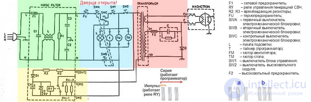
All the information given above is provided for consideration and for making a decision – whether or not it is worth undertaking the repair of the appliance yourself. If the answer to this question is nonetheless yes, we need one more piece of baggage of knowledge: the operating principle, typical faults, safety during work, and the actual electrical circuit of the design. The standard circuit of the appliance is shown in the picture on the left side, based on the design used by Samsung and other companies. On the green background is the mains filter, whose purpose is to prevent microwave energy from getting onto the power supply wires, which we'll examine further below. On the blue background is the EMB control module. Mustard-colored is the device for generating power supply pulses to the magnetron (UFI). In fact it is part of the control module, since it is located on the same printed circuit board as its components. But its faults are specific to it and have nothing in common with the other components, which is why we will study them separately as well.
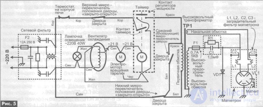
In Fig. 5, the timer-regulator (circled with a dotted line in the center of the figure) is intended to:
Regulate the magnetron's power;
Time the operation and switch off the oven once the timer has elapsed;
Emit a sound signaling that cooking is finished.
The mains filter houses the general-purpose fuse F1, which trips in most situations, as we will discuss below. Once the fault that caused it to blow has been fixed, a new F1 is installed with the same ratings – current, time, and trip temperature. It is needed for the general protection of the appliance against current overloads; do not install a "bug" (bypass wire) – it's better to just buy a new microwave right away.
The thermal fuse (thermal cutoff) is mounted on the housing of the component that reaches the highest temperature during operation, which in our case is the magnetron; it trips many times and restores its function once the temperature drops. If the oven shuts off due to overheating before the programmer switches it off, check the magnetron cooling exhaust fan for clogging – most likely you will need to clean the outlet grille or the inlet duct. If knocking, squeaking, or a louder hum than usual is heard during operation – it has most likely worn out over time and needs replacement.
Microswitches SWA, SWB, SWC – are the overall electromechanical interlock (EMB) system. The first two are triggered by the door latch tab located at the top, and the last one by the lower one. Our appliance, as already mentioned, belongs to the first hazard class and in most cases is used against the rules, i.e. without grounding, which is why it has a complex EMB system: dual-contact for opening, with a control contact for short-circuiting. One of the safety-engineering tricks is applied here: when you cannot be completely certain that an invisible hazard is unavoidable, you at least make it visible. The hazard we cannot see – dangerous radiation; the visible one – F1 burning out.
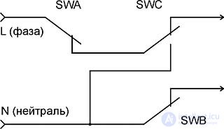
The EMB is one of the most important parts of the construction, it often fails due to a buildup of soot/grease film formed during cooking. Above is its diagram shown separately from the overall construction with the door closed. The picture clearly shows the process of the SWC circuit being short-circuited if SWA has stuck and the door is not closed, which is what burns out F1. False triggering can be avoided by having SWC switch more slowly compared to SWA. It is precisely for this reason that microswitches should only be replaced with identical models.
There is also a situation where all the microswitches show normal readings on continuity testing, yet F1 burns out when the door is opened. This symptom indicates the presence of grease/soot buildup on the switches, their trip timing has been disrupted, and the whole system's timing balance has been thrown off. Only replacing all three microswitches at once will help, as they cannot be disassembled and repaired.
If the oven does not start operating even with the door tightly closed, the same three switches may be at fault. Their contacts may fail to close due to the same grease/soot buildup.
Grease and soot
These are the most common causes of failures in cooking appliances; the deeper into the device we go, the more trouble we find from them. Lipids from microwave cooking don't boil, but they do evaporate, and the vapors settle wherever they please, forming a film of greasy soot. This is the cause of general malfunctions in entire assemblies and disruptions to mechanical operation, which we will examine further. If the grease/soot buildup is also slightly damp, it conducts electricity, which disrupts the operation of the control automation; in the absence of moisture, the film can be punctured by a voltage of up to 500V, which poses a danger to high-voltage assemblies. Grease/soot buildup causes the most damage in the microwave path, since that repair is the most expensive and difficult to carry out.
If you want to verify how thoroughly grease/soot buildup can penetrate everywhere, you can run an experiment. Take a brand-new pan with a lid, melt any fat on it until liquid, without covering it. Then let it solidify again, cover the pan with the lid, and leave it for 24 hours at room temperature. When the allotted time has passed, lift the lid and run your finger across it – it will be greasy and sticky, this is the settled greasy film. The effect of grease on the chambers, given the temperature that regularly rises above 100 degrees in it, becomes obvious. Its danger also lies in the fact that it does not turn black or brown, as it does on kitchen utensils, but is almost transparent and unnoticeable, though this does not reduce the harm it causes.
In an operating oven, with food loaded and the door closed, the process goes as follows. With the power regulator set correctly (we will examine this further), turning the timer knob to the required time closes SW1, which turns on the interior light and starts the turntable rotating, and the magnetron and convection fan begin blowing. After bringing them to operating condition, SW2 is engaged, which starts the pulse power generation device for the magnetron (PFU), and heating begins. After the timer returns to zero, both contacts and all assemblies open and the end-of-operation signal sounds. In simpler constructions, the spring is wound mechanically when the door is closed, and it is released by the timer cam.
Timer
This is a cam programmer combining electronics and mechanics; it is activated directly by the timer: a ribbon-spiral spring with a mechanism similar to a clock, or a micromotor equipped with a gearbox. A number of discs with cams are mounted on the timer shaft, which close and open groups of contacts.
Timer failures (let's abbreviate it this way) most often arise from greasy soot buildup. In second place – faults in the mechanical components. In third place – in mechanical designs without electronics, the spring weakens. You can tell that this particular assembly has broken by the following signs:
Some previous-generation LG models can exhibit a very unusual fault due to a clogged timer: the appliance turns on by itself and runs until shut off by the thermal cutoff. After the FU temperature drops, it starts up again. This fault is very dangerous, since running without a load leads to failure of the magnetron, and buying a new part is equivalent to buying a new oven. This phenomenon can often be observed during the off-season, when the heating hasn't been turned on yet, but only with the door closed. Investigating the causes of this reveals an SW1 stuck from grease and a clump of soot between SW2. Increased air humidity contributes to the formation of resistance, similar to that from the PFU's time-setting resistor (discussed below); the storage capacitor built up a charge and triggered the relay that supplies power to the magnetron.
Layers of grease/soot buildup in the turntable rotation mechanism and convection fan contribute to failures in other assemblies: food heats up unevenly, and vapor from fat coming from areas with elevated temperature is stronger. The result of this is burnout of the waveguide outlet window cover, and that is a difficult and expensive path repair. To avoid this situation, we take action right away as soon as we see intermittent turntable rotation or soot fouling of the convection fan grilles: disassemble the appliance and clean these assemblies. If it is possible to disassemble without touching the magnetron and the microwave path, we try to route everything around these assemblies. If the design does not allow reaching the fouling without touching the aforementioned parts, it is better to take it to a service center.
The pulse generation device for magnetron power operates on the following principle: via a low-power rectifier diode D1 and resistors R2/R3, the large-capacity electrolytic capacitor C4 is charged. Zener diode D2 is used to protect the low-voltage C4 and relay RY from high voltage. Once the voltage on C4 reaches a certain value, RY triggers, supplying 220V 50/60Hz to the primary winding of the magnetron power transformer, from which a microwave pulse is then sent into the chamber. After a certain interval, C4 loses its charge through the RY winding and releases, then the cycle starts again and again until SW2 fully opens or FU triggers. This circuit allows the radiation to be delivered in pulses, and it is illustrated in the figure above, lower left part.
The simplest power adjustment is done by switching R2/R3. This also changes the charge time of C4, but does not affect the discharge time. As a result, the ratio of the pulse repetition period to the pulse duration changes, giving rise to a duty cycle in their sequence. This system represents pulse-width modulation (PWM), and it is found not only in digital models. The average output power from the magnetron is determined by the duty cycle, and due to thermal inertia, it affects the food in the chamber as if it were a constant value.
The magnetron stores energy in the transformer windings so that it is not released in a single burst that no screen could withstand upon its instantaneous disappearance; the primary winding of the transformer remains connected to the 220V neutral through high-resistance resistors R4. Removing this component leads to hum even in an otherwise properly functioning unit, even with grounding present. When the R4 solder joints become fouled, the appliance takes longer to complete the pulse, its temperature rises to a critical level, and it shuts off due to overheating.
Some models are equipped with dual PWM for stable high-performance magnetron operation at an average power level. To provide this technically, additional discs with varying numbers of cams and their own contacts are mounted on the timer shaft. Power is regulated by switching PFU power to different groups. Power pulses come in groups, one after another, either more or less frequently – positions a and b on the diagram, while the pulse duty cycle itself does not change.
In the PFU, the relay often fails, as the contacts carry a large current.
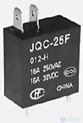
In such a situation, the magnetron will not operate and, accordingly, the microwave will not raise the temperature, although the other functions work properly. To check this, the RY winding leads are connected to a power source with adjustable output, and a multimeter in ohmmeter mode is connected to the leads of the closing contacts. We raise the voltage on the winding from 3 to 24V; if the tester does not show a short circuit, we replace RY.
The oven heats less than what is indicated on the regulator, the fault will develop gradually further, and the knob will need to be turned to an increasingly higher temperature. C4 may have lost capacitance; only replacement with an identical part will help.
Power may also drop due to the magnetron's natural end of service life. This applies if the unit is more than 5 years old and has been used very intensively, and the power dropped slowly, over the course of months rather than days or weeks. A service center with the necessary equipment can determine this precisely in a lab.
From time to time a pop is heard and the oven stops heating. Opening the appliance, we see that the C4 casing has bulged and developed a crack. The cause of this may be a breakdown of D1 or a failure of D2. Both are replaced along with C4, and RY is also checked right away, as its winding could have been affected too.
MICROWAVE OVEN CONTROL UNIT |
Control units for microwave ovens come in two types: electromechanical and electronic. There are two main functions that the control unit must perform: maintaining the set power level and switching off the oven after the set operating time has elapsed. Regardless of the type of implementation, all ovens handle these tasks equally successfully. Since the electronic control unit contains a micro-computer with rich potential capabilities inside it, microwave oven designers always have an underlying desire to make use of these capabilities in some way. And here everyone gets creative in their own way. Ranging from built-in clocks to snippets of musical pieces signaling the end of operation. All of this can be regarded as certain extras that do not affect the performance of the main functions.
The level of microwave power delivered to the cooking cavity is regulated by the switching time of the actuating device, which may be a relay, a microswitch, or a triac. The actuating device periodically turns the magnetron's power supply on and off in accordance with the selected power level. As an example, Fig. 2.25 shows the operating cycle of a Pluton microwave oven for various power settings. The full cycle is 22 seconds long. Depending on the selected power level, the magnetron is switched on for only a certain portion of a single cycle, and each subsequent cycle periodically repeats this sequence of actions.
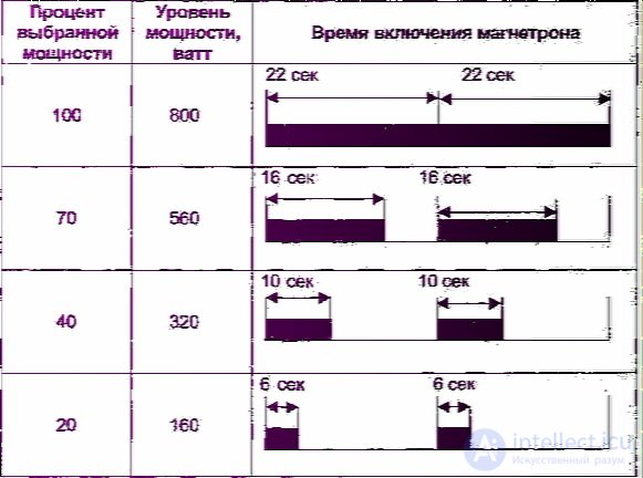
Fig. 2.25. Magnetron on-time duration at various set power levels
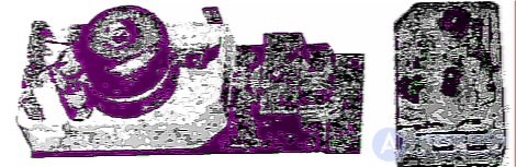
Fig. 2.26. External appearance and internal components of a typical electromechanical microwave oven timer
Although many microwave ovens use a triac as the actuating device, allowing smooth regulation of high power levels, power to the magnetron is always supplied in the form of pulses. Their duty cycle changes depending on the required power. The very rare and not entirely successful exceptions only prove the rule. The main reason for this design approach is that it is much simpler and more reliable, while at the same time the method of power regulation has no effect whatsoever on the cooking process.
The electromechanical control unit consists of a timer and an associated stepped power-regulation mechanism. These parts are often housed in a single enclosure. The timer usually includes a micromotor, a gear reducer, a mechanical bell, and a system of contacts and microswitches that turn the power supply on. A typical timer design is shown in Fig. 2.26.
Since the timer is electromechanical, its faults can be related to either mechanical or electrical assemblies. In the first case, this is usually a failure of the gear reducer. A typical fault is broken teeth on the plastic gears. In this case the timer motor runs, but time is not counted, so the microwave oven does not automatically switch off once the set time has elapsed. In most cases this fault can be fixed using the method shown in Fig. 2.10.
Faults in the electrical part show up as the internal contacts failing to close or open. Failure of the micromotor is also possible, although in practice this happens extremely rarely. The timer usually has two pairs of contacts. The first, which we will conventionally call the main pair, closes the circuit that supplies power to the magnetron fan, the cavity light, and the micromotors of the turntable and timer. In the magnetron power circuit, in series with the main pair of contacts, there is an additional pair that periodically turns the magnetron power supply on and off in accordance with the selected power mode. The additional contacts are usually a built-in standard microswitch. Because of the large current flowing through both pairs of contacts (about 6 A), they can become burnt. Once the burning process starts, it will grow like an avalanche until the contact finally fails completely. The more badly a contact is burnt, the higher its resistance, and the more power will be dissipated on it as heat. A broken microswitch must be replaced, while non-working main contacts can be cleaned. A contact must be springy, so its blades sometimes need to be bent slightly. To reach the contacts, the timer must be disassembled. This must be done carefully, taking care not to lose the springs and small parts present inside when removing the cover.
In some microwave ovens, for example MOULINEX, the bell must first be removed in order to disassemble the timer. Note that the screw holding the bell may have a left-hand thread.
The block diagram of the electronic control unit is shown in Fig. 2.27.
The main element of the control unit of a microwave oven is a microcontroller, which is programmed with the sequence and values of output signals depending on the information arriving at its inputs. The main source of input information is the keypad, on which the user sets the time and cooking modes. In addition, the microcontroller's input receives a signal indicating that the microwave oven door is closed, and signals from various sensors, if present. Information about the selected operating mode and the time remaining until the program finishes is shown on the display. During operation, the microcontroller turns various actuating devices on and off, including relays, triacs, piezoelectric buzzers, and so on. For power matching, the actuating devices, and sometimes the display devices as well, are connected through buffer amplifiers. The control unit also contains a power supply consisting of a step-down transformer, one or more rectifiers, and voltage regulators.
To repair the control unit it must be disconnected from the microwave oven, supplied with voltage from an independent source, and a short-circuiting jumper must be placed on the interlock input.
Let us look in more detail at the main assemblies of the control unit, the faults typical of them, and the methods for fixing them.
Keypad
The overwhelming majority of microwave ovens have a pseudo-touch membrane keypad. Its operating principle is shown in Fig. 2.28.
The keypad is made as a three-layer polymer film glued to a rigid surface. On the inner sides of the top and bottom layers, metallized or carbon contact pads are applied, joined by a network of conductors into several buses. Where the contact pads are located, the middle layer has cutouts, and on the front side of
the keypad, button images are printed. When a button image is pressed, the contact pads close, sending the corresponding signal to the microcontroller. When the button is released, the elasticity of the material returns the keypad to its original shape, and the contact opens. As an example, Fig. 2.29 shows the internal structure and wiring connections of one of the most commonly encountered keypads, from the control unit BUVI-2*.
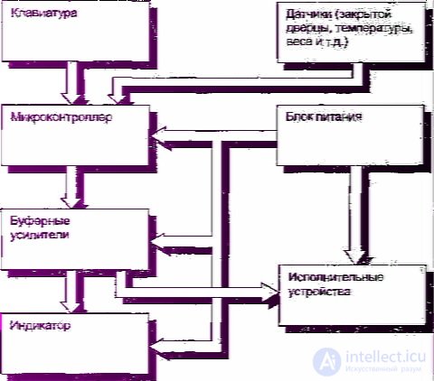
Fig. 2.27. Block diagram of the electronic control unit of a microwave oven
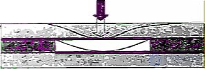
Fig. 2.28. Cross-section of a membrane keypad in the area of the closing contact
Doubts about the keypad's functionality arise when pressing button images either has no effect at all, or does not produce the expected result. Of course, provided your expectations do not go beyond the operating instructions.
To make sure that faults in the control unit are caused by the keypad, you can remove the keypad from its connector and briefly short, with a piece of wire, the control unit leads that are supposed to be closed by the button suspected of sabotage. If the effect matches what is expected, then your suspicions are justified and the keypad needs to be repaired. The difficulty lies in the fact that you need to know beforehand which leads are closed by which button. If the required information is not given in this article, there are two possible courses of action. The first approach is radical. You need to peel the keypad off the control unit and, using the trace layout visible from the reverse, transparent side, draw up a wiring diagram. The second approach is the so-called trial-and-error method. It can be used when the input and output buses are interconnected, as, for example, in Fig. 2.29. In this case the wiring dia*
gram can be worked out by shorting each input bus to each output bus in turn, analyzing the result each time. The difficulty here is that some buttons, for example START, can only be activated if certain preliminary information has been entered. Therefore, drawing up the diagram will take place in several stages. First, note the connections that can be established immediately, and then, using the established contacts for preliminary entry, determine the missing links of the wiring diagram. Fans of puzzles and brain-teasers will get real enjoyment out of this.
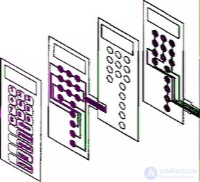
Fig. 2.29. Internal structure of the membrane keypad from the BUVI-2 control unit
Typical faults related to the operation of the keypad are:
- loss of contact in the connector,
- a break in the conductive traces,
- sticking.
The first case is the simplest, and it is often enough to fix the contact in the connector to resolve the problem that has arisen. Therefore, it always makes sense to start precisely by checking this link, especially if the keypad leads in the connector have some play and are not rigidly fixed.
A break in the conductive traces most often occurs at the keyboard's leads. This is because that area is most prone to deformation and, in addition, the conductors there are exposed, unlike the rest of the keyboard, where the conductive coating is covered by film on both sides. Defective traces can be found by examining them against the light. The easiest way to restore damaged sections is with conductive adhesive. The technology of such a repair is so obvious that no explanation is needed. If such adhesive is not available, you can cut a thin strip of copper or aluminum foil and stick it onto the damaged section with tape. It is not recommended to try to solve the problem with a soldering iron, since when heated, the metal that the conductive traces are made of will ball up and thus only make matters worse. Even if you manage to solder a jumper using low-temperature solder, the reliability of such a connection will be low. After some time, the solder will come off, taking part of the conductive traces with it.
In some cases, a break in the traces occurs inside the keyboard. Besides manufacturing defects, this can be caused by excessive force when pressing keys and by moisture getting onto the conductive surface. As a rule, the traces are made by sputtering a thin layer of silver onto a polymer film. The presence of moisture causes oxidation of the silver, which can cause the trace to break down. It is characteristic that a short between neighboring traces can occur at the same time, since water saturated with silver ions is a good conductive electrolyte. Therefore, when maintaining a microwave oven, the keyboard can be wiped with a damp cloth, but it must not be washed.
A few words on how a break in the conductive traces can be detected. To do this, the input and output buses need to be connected together and connected to a tester, as shown in fig. 2.30.
With this connection scheme, pressing any button will measure the resistance of the corresponding connection. If the conductive traces are broken somewhere, then pressing certain keys will not cause a change in the instrument's readings. Moreover, depending on which specific keys do not work, the approximate location of the defective section can be determined. For example, if in the previous figure the section marked with a thickened line has a break, then buttons 5 and 6 will not work.
If none of the buttons work, a possible cause of this may be a contact stuck closed in some button or a short between the buses. If a button is to blame, this can be checked using the circuit in fig. 2.30. the tester's readings will register a short being present while none of the buttons is pressed. By removing the jumpers connecting the conductive traces and measuring the resistance between each pair of input and output traces, the stuck button can be located. The cause of such sticking can be deformation of the film and delamination of the conductive coating in the area of the contact pads. The latter case is typical for keyboards in which the conductive coating is something resembling carbon. The substance that the contact pads are made of, flaking off, fills the gap between them and, once enough accumulates, leads to a short.
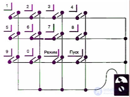
Fig. 2.30. Detecting a break in conductive traces in a membrane keyboard
Sometimes a short occurs between neighboring traces. This mostly happens when moisture gets inside the keyboard, and as a rule, near the ribbon lead, where there are small gaps. Such an unwanted contact can be found by measuring the resistance between neighboring traces. It should be infinite or close to it. Otherwise, you can unglue the keyboard from the control unit's housing and try to find the location of the short through the transparent back side.
Theoretically, it is considered that the keyboard, like, indeed, most parts of a microwave oven, is not repairable. And one has to act according to the saying: if you can't, but really want to, then you can. If an internal break or short has occurred in the keyboard, opening it up is required to restore its functionality. To do this, the layers glued together need to be separated at the location of the suspected defect, the defect eliminated, and everything glued back together again. So that the autopsy doesn't reveal that the patient died from the autopsy, during this process adhesive must not be allowed to get on the current-carrying traces, and it is advisable not to touch them with your hands. But even with all precautions observed, such an operation sometimes results in part of a trace ending up on one layer and part — on the other. So that contact does not disappear during subsequent gluing, a thin strip of foil needs to be laid along the damaged section (or conductive adhesive can be used).
Recently, in addition to buttons on the front panel of the control unit,
продолжение следует...
Часть 1 Diagnostics and Repair of Microwave Ovens
Часть 2 Composition of a microwave oven - Diagnostics and Repair of
Часть 3 High-voltage test bench - Diagnostics and Repair of Microwave Ovens

Comments