
Lecture
Это окончание невероятной информации про ДИАГНОСТИКА КАБЕЛЬНЫХ.
...
kV networks is based on measuring, near the overhead line, the level of higher harmonic components of the zero-sequence current magnetic field using a magnetic sensor tuned, in this mode, to a frequency of 550 Hz."Filin - 6" ultraviolet flaw detector.
The "Filin - 6" electro-optical flaw detector converts the ultraviolet radiation of discharge processes into visible light and superimposes it on the screen with the image of the inspected object in the visible spectrum. It detects defects such as:
-·damage to the sealing of pin insulators and the presence of surface microcracks in porcelain;
-·presence and assessment of the degree of contamination of any insulators;
-·damage to the integrity of overhead line wire conductors;
-·punctured (zero) porcelain insulators in a string;
-·defects in the installation of suspensions, inter-phase spacers of overhead lines, cable terminations, contact connections, and many others.
The camera allows inspections to be carried out while moving at speeds up to 250 km/h, and to operate at illumination levels down to 100 lux, that is, on a cloudy day or right after sunset (figure 5. 13).
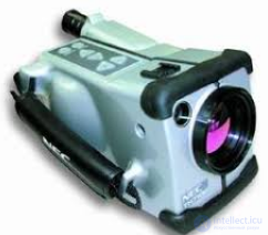
TH7102 thermal imager by NEC (Japan) (figure 5. 13).
Technical characteristics of the thermal imager:
|
Figure 5. 13 - TH7102 thermal imager |
- temperature measurement range - from – 40 °C to + 500 °C (Expandable to + 2000 °C);
- temperature resolution - better than 0.08 °C;
- temperature measurement error - ± 2 %;
- spectral range - 7.5 - 14 µm;
- detector type - Uncooled microbolometer array ("Boeing", fourth-generation array) 320x240 elements.
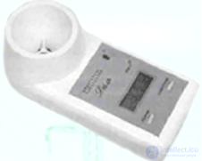
"Dal" ultrasonic distance meter allows determining the dimensions of an overhead power line (distances from the ground to the wires, distances between wires) without approaching the current-carrying parts and without de-energizing the line.
The "Dal" meter makes it possible to determine distances to three wires located one above another, with storage and sequential digital display of the distance to each of the wires.
|
Figure 5.14 - "Dal" ultrasonic distance meter
|
"Dal" distance meter
|
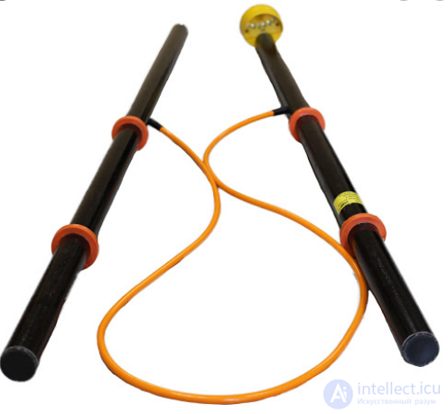
Figure 5.15 - UPP-10M fault-locating device
|
has the following characteristics:
- measurement range - 3.5 – 15 m;
- distance measurement error - no more than 1% (figure 5.14).
The indicator can be used to check the serviceability of protective grounding on energized electrical equipment, as well as to determine the location of hidden wiring energized at 380/220 V, and to check the correct installation of lighting switches, etc.
The instrument is equipped with visual and audible alarm systems, as well as a device for monitoring their functionality.
Fault location device type UPP-10M is intended for use in overhead and cable electrical networks of 6 - 10 kV by mobile field crews to speed up the identification of faulty lines or their sections in the presence of single-phase-to-ground faults. The device makes it possible to avoid trial energization to check for a possible short circuit, which is hazardous for equipment and personnel, especially in networks with high short-circuit currents. The device can also be used for phasing of a 6 - 10 kV network.
By its operating principle, the device is a high-voltage half-wave AC rectifier operating at a frequency of 50 - 60 Hz. By measuring, with the device, the current value between the working voltage circuit of 6 - 10 kV and the phases of the line being tested, one can judge the presence or absence of faults on it.
The device consists of two hollow polyethylene rods. The electrical circuit elements are placed inside the rods. The connection between the diodes and resistors is made with flexible wire in high-voltage insulation. Contact terminals are provided at the ends of the rods for touching busbars in electrical installations. The pointer indicator - a milliammeter - is mounted on one of the rods near the limiting ring, on the working part (figure 5.15).
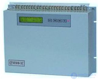
Device IMF - 1C is intended for the direct determination of the distance to the location of two-phase and three-phase short circuits on overhead power transmission lines with a voltage of 6 - 35 kV with an isolated or compensated neutral.
The device's operating principle is based on measuring the vector diagram of currents and voltages in a fault condition, followed by calculating the distance to the fault location using line parameters previously entered as settings. Monitoring of the current vectors and comparison of their values with the settings to determine the presence of a short circuit is performed continuously. When triggered, the device outputs fault information to the indicator and closes the contacts of the "Signal" relay (figure 5.16).
The device is equipped with automatic built-in monitoring of the serviceability of the main internal units, with a failure signal issued via the contacts of the "Failure" relay.
|
Figure 5.16 - Device IMF-1C for determining the distance to the location of short circuits
|
The IMF-1C device is equipped with a communication line interface for connecting several devices to a single computer. This makes it possible to remotely set the settings, perform a "trial start", and read fault data for subsequent processing on the computer.
Ice-loading telemetry systems STGN are intended for continuous measurement of ice loading on phase conductors and overhead ground wires of overhead power transmission lines of various voltage classes
Unlike existing systems, the unified STGN equipment can be used as part of a regional information system with an arbitrary number of ice-load monitoring points on various overhead lines. STGN equipment is produced with transmission of ice-load information by low-frequency pulses, DC voltage, or a combination of the two. The choice of information transmission method depends on the type of overhead line, the network configuration and operating modes, and the number of ice-load monitoring points on the overhead line. Information transmission in STGN is carried out over the channel: "phase-to-ground" - on overhead lines of 6 - 35 kV with an isolated neutral; "insulated overhead ground wire - to ground" - on overhead lines of 110 kV and above with a solidly grounded neutral; radio channel. The STGN equipment consists of:
- a contactless magnetoelastic ice-load sensor (DGN), installed between the crossarm and the insulator string of the overhead line. The design of the DGN, series DMS, depends on the type of overhead line and the loads being measured;
- a line converter (LP) and a receiving converter (PP), which perform, respectively, encoding at the monitoring point and decoding of the DGN signal at the receiving point. The design of the unified LP and PP depends on the method used to transmit ice-load information. The receiving converter provides indication of ice loading at the receiving point and outputs analog and relay signals into the signaling and telemechanics circuits.
The systems are distinguished by ease of setup and reliability in operation, and provide sufficiently accurate continuous monitoring of ice loading on overhead line conductors. This allows power system operating personnel to timely form an optimal strategy for combating icing in the region and to control various de-icing installations on overhead lines.
Review questions
1 What advantages does the use of rectified voltage have for testing cable lines (CL)?
3 List the types of CL faults.
4 Why is a cable line burned through (thermal fault burning)?
5 Which CL monitoring methods are classified as remote, and which as topographic?
6 The purpose and physical operating principle of the oscillatory discharge method, the pulse, bridge, induction, acoustic, and potential methods of CL monitoring?
12 How is the CL service life forecasted using the method of voltage response in the cable insulation?.
13 What methods are used to assess the service life of cables with polyethylene insulation?
14 The purpose and operating principle of the instrument "IRK-PRO version 5.10.00"?
15 The purpose and operating principle of the digital reflectometer Reis-205"?
16 What methods are used for diagnosing overhead line (OL) insulators?
17 The operating principle of the instrument for diagnosing OL conductors?
Часть 1 5. Diagnostics of Cable and Overhead Power Lines
Часть 2 - 5. Diagnostics of Cable and Overhead Power Lines

Comments