Lecture
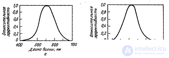
The purpose of photometric measurements is to quantitatively describe the brightness of the light [6-8]. The relationship between the photometric and energy characteristics of the radiation is established by the function of the luminous efficiency shown in Fig. 3.2.1, and [9]. This curve is approved as an ICE standard. It determines the spectral sensitivity of the visual system of some typical (standard) observer.

Fig. 3.2.1. Relative spectral light efficiency [9]: a - for daytime vision; b - for night vision.
In essence, this curve is a standardized version of the spectral sensitivity curve of cones, shown in Fig. 2.2.2, for day vision at relatively high levels of illumination. The standard luminous efficacy function for night vision at relatively low light levels is shown in Fig. 3.2.1, b. Most imaging systems are designed based on relative luminous efficiency for daytime vision.
Subjective sense of brightness caused by a light source with a spectral density of radiation  , is determined by its luminous flux, which is expressed as
 (3.2.1)
Where  - relative luminous efficiency, a
  - constant. If the luminous flux measured in lumens, then
  lm / w The source of monochromatic light with a power of 1W, whose wavelength corresponds to the maximum of the relative luminous efficacy curve (i.e.
  nm), gives a luminous flux of 685 lm.

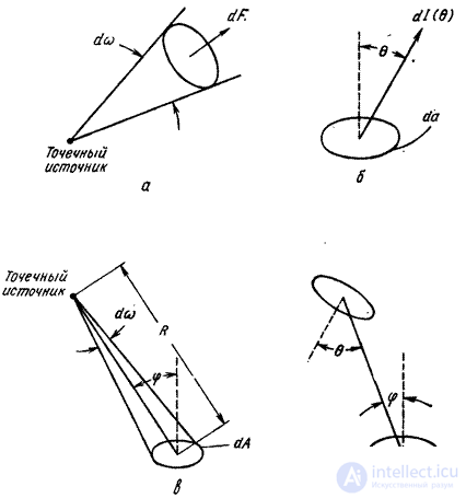
Fig. 3.2.2. To the definition of photometric values: a - radiation of a point source; b - radiation of an elementary site; in - the illumination created by a point source: d - the illumination created by an extensive source.
Another important characteristic of a light source is the spatial distribution of its radiation. Consider a point source emitting luminous flux in all directions (Fig. 3.2.2, a). The ratio of the infinitely small luminous flux  emitted to an infinitely small solid angle
  , to the magnitude of this angle is called the intensity of light:
 (3.2.2)
This value is measured in candela. An extended source is characterized by brightness (Fig. 3.2.2, b), equal by definition
 (3.2.3)
Where  - infinitely small power of light emitted from an infinitely small area
  in the direction of the angle
  with normal to the surface. The unit of brightness is candela on
  or nit.
An extended light source is diffuse if the Lambert law is true
 (3.2.4)
Where  - infinitely small power of light emitted perpendicular to the surface. For such a source, the brightness
 (3.2.5)
does not depend on the direction of observation. In imaging systems, illuminated frosted glass is often used as an approximation to an ideal diffuse light source.
The brightness of the radiation source is a measure of the luminous flux emitted from a unit of its surface area in a given direction to a single solid angle. The magnitude of the light flux incident on the observed surface is determined by its illumination. Let a point source emit light  in solid angle
  at an angle
  with a normal to the observed surface (Fig. 3.2.2, c). Angle
  covered area
  on this surface. Illumination is by definition equal to
 (3.2.6)
From the relation (3.2.2) and fig. 3.2.2 it follows that
 (3.2.7)
Where  - distance from the source to the surface. Therefore, when illuminated by a point source, the illumination is determined by the ratio
 (3.2.8)
which expresses the inverse square law for radiation. To determine the illumination created by an extended source, it must be represented as a set of point sources, and then the illumination received from these point sources is added. Turning to fig. 3.2.2, g and expression (3.2.8), we obtain that the infinitely small illumination of the site  observable surface created by the site
  radiating surface there
 . (3.2.9)
From expressions (3.2.3) and (3.2.9) we get
 (3.2.10)
To calculate the light  expression (3.2.10) should be integrated over the surface of the illuminating object.
Based on the above theoretical propositions, two important photometric results can be obtained for the optical system.

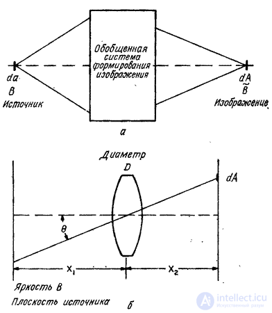
Fig. 3.2.3. Connection of the source brightness with the brightness and illumination of the image: a - brightness of the source and image: b - brightness of the source and illumination of the image.
Consider the generalized imaging system shown in Fig. 3.2.3, a. Infinitely small playground  the surface of a diffuse object with brightness
  displayed in an infinitely small area
  observable surface that acquires brightness
  . You can show [8, p. 189] that
  if the reflection coefficients of both surfaces are the same. Thus, the imaging system does not change the brightness, if you do not take into account the loss due to absorption and scattering of light. In fig. 3.2.3, b shows how the display of an extended diffuse source with brightness
  on the observed surface through a simple thin lens. Infinitely low illumination on an infinitely small area
  [8, p. 190] is equal to
 (3.2.11)
Where  - diameter of the lens,
  - the angle of intersection of the main rays passing through the center of the lens, and
  - the distance from the center of the lens to the observation point. Thus, the illumination of the points of the observation plane decreases with distance from the optical axis as the fourth power of the angle between the given direction and the optical axis. notice, that
  . Additional loss of illumination caused by the absorption and scattering of light in the optical system. In addition, there may be losses due to vignetting, when the oblique rays that make up a large angle with the optical axis are completely lost.
In the future, when considering image processing systems, in order not to enter into unnecessary details, issues related to photometry will be excluded as far as possible. In addition, as is commonly done in the image processing literature, the term “brightness” will be used to mean luminous flux, luminous intensity, and luminance itself.
Comments
To leave a comment
Digital image processing
Terms: Digital image processing