Lecture
It was shown that the color  can be described by color coordinates
  ,
,  ,
,  for a given set of primary colors. Alternatively, color can be defined by chromaticity coordinates.
  ,
,  and brightness
  . You can also describe color using any linear or non-linear reversible function of color coordinates or chromaticity and luminance coordinates. From the expression (3.5.5) it is clear that the linear transformation of color coordinates is simply a transition to a new set of primary colors. Appendix 2 provides formulas for converting color and chromaticity coordinates for different coordinate systems.
For a quantitative description of the colors proposed many different coordinate systems. Below are those that are of historical and theoretical interest.
In 1931, the MKO developed a standard set of monochromatic primary colors: red with a wavelength of 700 nm, green - 546.1 nm, and blue - 435.8 nm [4]. The units of the color coordinates are chosen so that the coordinates  ,
,  ,
,  white light with a uniform spectral density in the visible part of the spectrum were the same. The set of primary colors is determined by the addition curves for the spectral colors shown in Fig. 3.6.1.
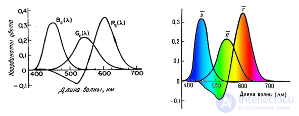
Fig. 3.6.1. The addition functions of the coordinates of the spectral primary colors of the MCO (red - 700 nm, green - 546.1 nm, blue - 435.8 nm) [11].
These curves were obtained in experiments on equalizing colors with a large number of observers. According to the results of the experiments, the so-called standard MKO observer was determined. Data for a field of view of 2 ° was published in 1931. Then, results were obtained for a field of 10 °. In television and phototelegraphy, it is better to use data for a 2 ° field. In fig. 3.6.2 presents a graph of chromaticities in the coordinate system of the spectral primary colors of the MCO, as well as the colors of the phosphors of the television receiver of the US color television system NTSC. The triangle defined by the colors of the phosphors encompasses the chromaticities of all reproducible colors.
Television receivers in the United States use kinescopes with three phosphors — red, green, and blue [14]. The coordinate system of the receiver NTSC, determined by the colors of the phosphors, can be associated with the coordinate system of the spectral primary colors of the MKO by a simple linear transformation. In fig. 3.6.3 shows a graph of chromaticity in the coordinate system of the receiver NTSC. In this system, the units of measurement of coordinates are normalized so that the values of the coordinates at which the reference white color is equal are the same. The phosphors of the NTSC receiver are not sources of monochromatic light, therefore the color gamut determined by them (the set of reproducible colors) is narrower than when using the MKO spectral primary colors.
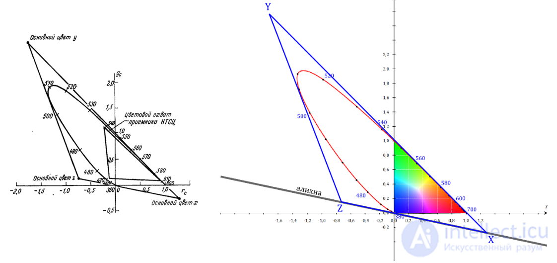
Fig. 3.6.2. Graph of chromaticity in the coordinate system of the spectral bases of the colors of MKO [11].
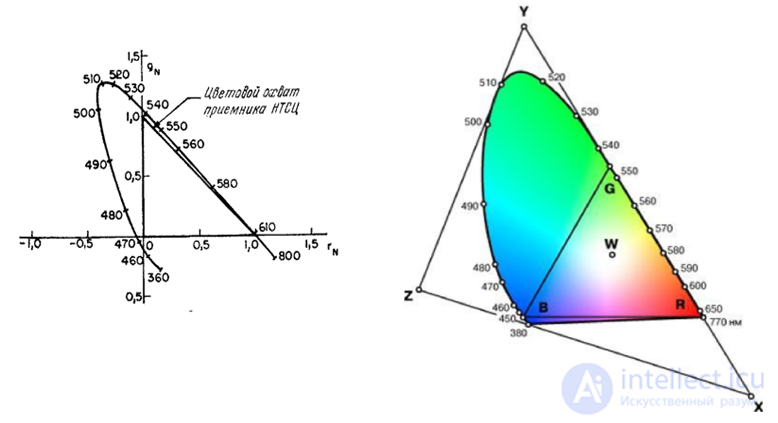
Fig. 3.6.3. Graph of chromaticity in the coordinate system of the receiver NTSC.
Coordinate system XYZ MKO
The coordinate system of the spectral primary colors of the MCO has one drawback for colorimetric calculations: the color coordinates sometimes turn out to be negative. Faced with this difficulty, the ICE has developed a coordinate system with artificial primary colors, in which the coordinates of the colors of the spectral colors are positive [4]. Artificial primary colors are shown in Fig. 3.6.2. They are chosen so that the Y coordinate is equivalent to the brightness colors  . In fig. 3.6.4 presents a graph of chromaticities in the system XYZ MKO with reference white light with uniform spectral density.
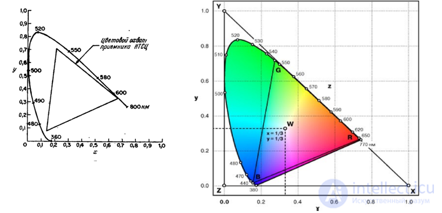
Fig. 3.6.4. Graph of chromaticity in the coordinate system XYZ IOC [4].
The coordinate system of transmitted signals NTSC
In the color television system NTSC developed in the USA, three color coordinates are transmitted.  ,
,  ,
,  [14]. Coordinate coincides with the coordinate systems
  ; It corresponds to the brightness. The remaining two coordinates and together describe the hue and saturation. The reasons for the transfer of coordinates , , instead of coordinates
  ,
,  ,
,  directly from the output of the transmitting chamber are the following: 1) signal can be used by existing monochrome television receivers and 2) signal bandwidth and can be reduced without noticeable distortion of images. Applying this reduction and an ingenious modulation method, we were able to transmit the full analog color television signal in the same frequency band as in the single-color image.
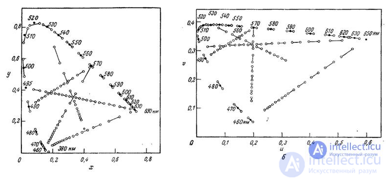
Fig. 3.6.5. Comparison of subtle color differences in coordinate systems and  , The magnitude of the differences increased 10 times [12]: a - color differences in the graph of chromaticity
  ; b - color differences on the graph of color
  .
.
It is desirable to have such a coordinate system so that equal changes in chromaticity coordinates correspond to equal changes in color perception. The graph of chromaticity (Fig. 3.6.5, a) shows the difference in colors, which are perceived the same way [12, 17]. This graph, as well as other experimental results, indicate that the human eye is most sensitive to changes in blue, moderately sensitive to changes in red, and has the least sensitivity to changes in green.
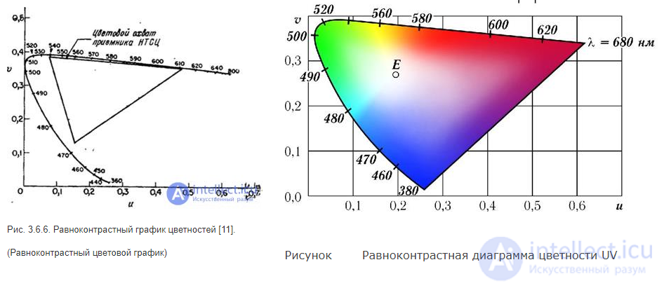
Fig. 3.6.6. Equivalent graphs of colors [11].
In 1960 MCO adopted an equal-contrast coordinate system, in which, with a good approximation, equal changes in chromaticity coordinates correspond to barely noticeable changes in color tone and saturation. In fig. 3.6.5, b shows the data in fig. 3.6.5, and in equal contrast coordinates. Transition from coordinates  , ,
, ,  to equal contrast coordinates is a linear transformation. The chromaticity coordinates in both systems are related by the following relations [18]:
 (3.6.1a)
 (3.6.16)
The graph of chromaticities in the equal-contrast coordinate system is shown in Fig. 3.6.6.
Coordinate system  *
*  *
*  *
*
Coordinate system * * * there is a development of a coordinate system in order to obtain a color space in which individual changes in chromaticity and luminance are perceived in the same way. Coordinates  by definition [19] are equal
 (3.6.2a)
 (3.6.2b)
 (3.6.2в)
with units of brightness selected so that the brightness varies from 0 to 1, and  and
and  —Coordinates of chromaticity reference white.
Coordinate system 
Coordinates  ,
,  ,
,  there are just polar coordinates for the system * * * . By definition, they are equal [11]
 (3.6.3a)
 (3.6.3b)
Coordinate determines the color saturation, and - Color tone.
Coordinate system 
Coordinate system , while still fairly simple for colorimetric calculations, provides a relatively accurate representation of colors according to the Munsella color system [20]. The color coordinates in this system are
 (3.6.4a)
 (3.6.4b)
 (3.6.4в)
Where  ,
,  ,
,  - coordinates of the reference white color in the system . Coordinate
  determines the brightness of the color
  - the ratio of red and green colors,
  - the ratio of blue and yellow. Many colorimeters, manufactured by industry, give the values of these coordinates.
The coordinate system of the spectral primary colors system , and others can be considered as the result of a linear transformation of the coordinate system of the NTSC receiver. Color coordinates , , NTSC receivers are strongly correlated with each other [21]. When developing effective methods for quantizing and coding color images, it is convenient to deal with uncorrelated components. If the covariance matrix of quantities is known , , , then we can construct a system of orthogonal uncorrelated coordinates using the Karhunen-Loeve transform. Transformation matrix  consists of the eigenvectors of the covariance matrix and is determined by the following relationship:
 (3.6.5)
Where  - eigenvalues of the covariance matrix and
 (3.6.6a)
 (3.6.6b)
 (3.6.6b)
 (3.6.6g)
 (З.6.6д)
 (3.6.6e)
As noted in ch. 2, when considering models of human color vision, indirect measurements of spectral sensitivities were performed.  Cones of three types.
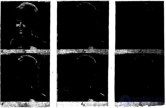
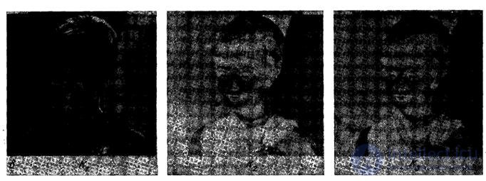
Fig. 3.6.7. The components of the color image: a is the coordinate system of the NTSC receiver; b - coordinate system of cones; в - coordinate system of Karunen-Loeve.
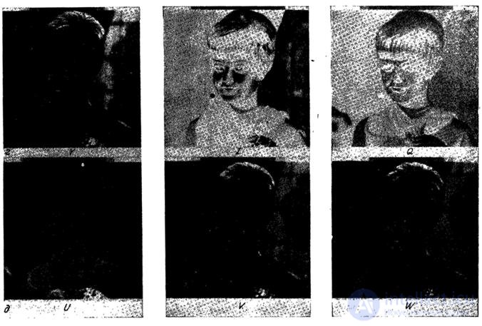
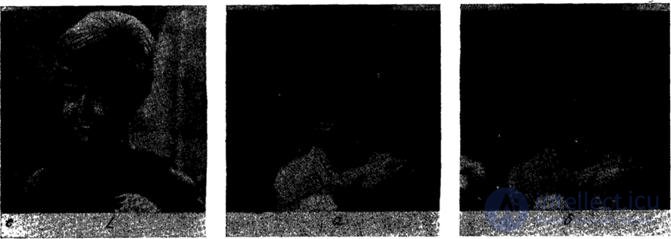
Fig. 3.6.7. (continued): d - coordinate system of transmitted signals from the NTSC; d - equal contrast coordinate system: e - coordinate system .
It turned out that the spectral sensitivities are connected linearly with the addition functions obtained from the colorimetric experiments. Consequently, cone signals  can be viewed as color coordinates. These coordinates are related to coordinates.
  following linear transformation [22]:
 (3.6.7)
In fig. 3.6.7 shows the components of a color image for several coordinate systems. It should be noted that the red, green and blue components are highly correlated. In some coordinate systems, one of the components contains most of the image energy, while the others seem less detailed.

Comments
To leave a comment
Digital image processing
Terms: Digital image processing