
Lecture
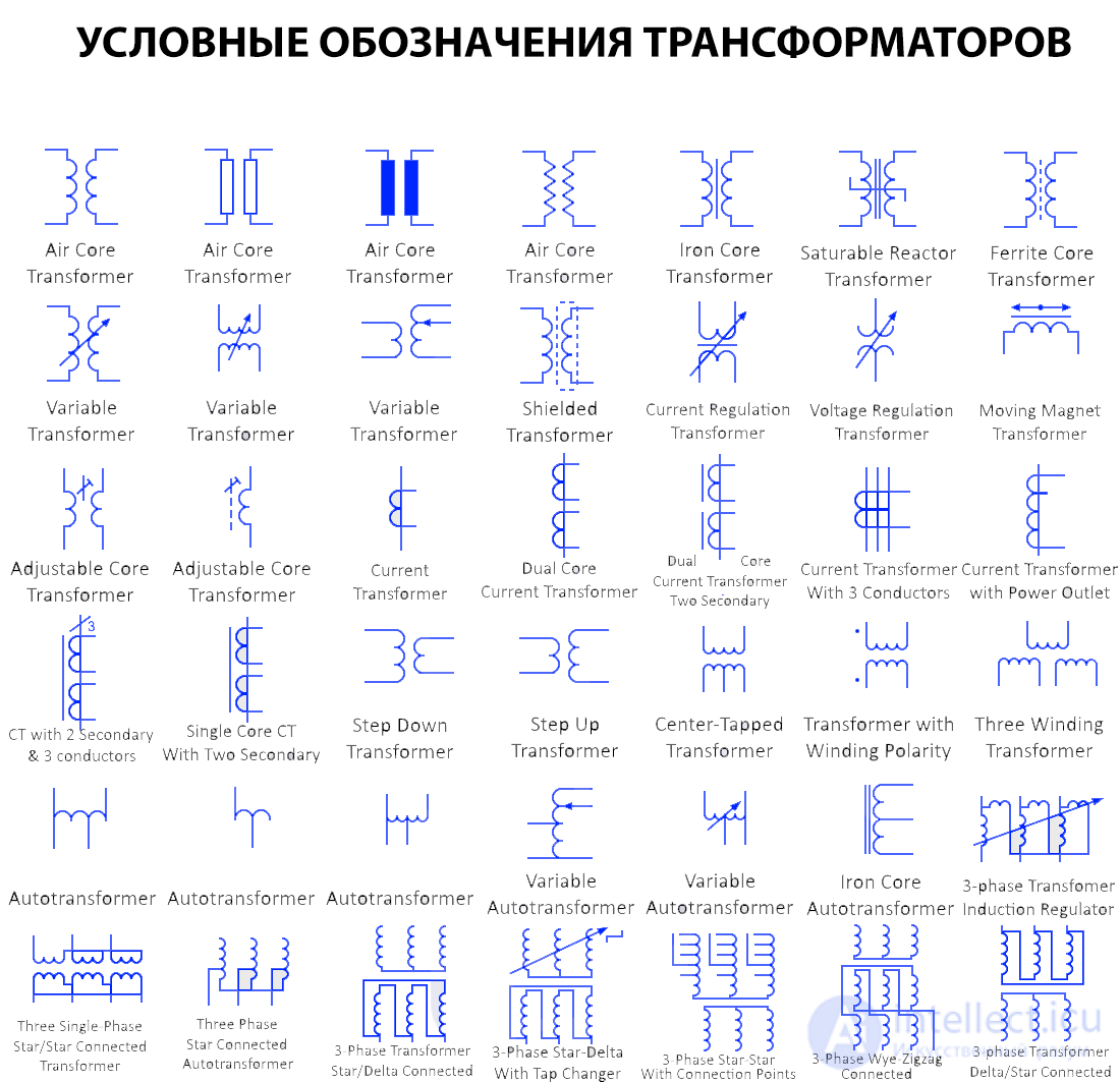
The symbols used for transformers in electrical diagrams depend on their type and purpose. Below are the main symbols used for various kinds of electrical transformers:
Below is a list of various types of transformer symbols. The list of single-line transformer symbols is given at the end of this post.

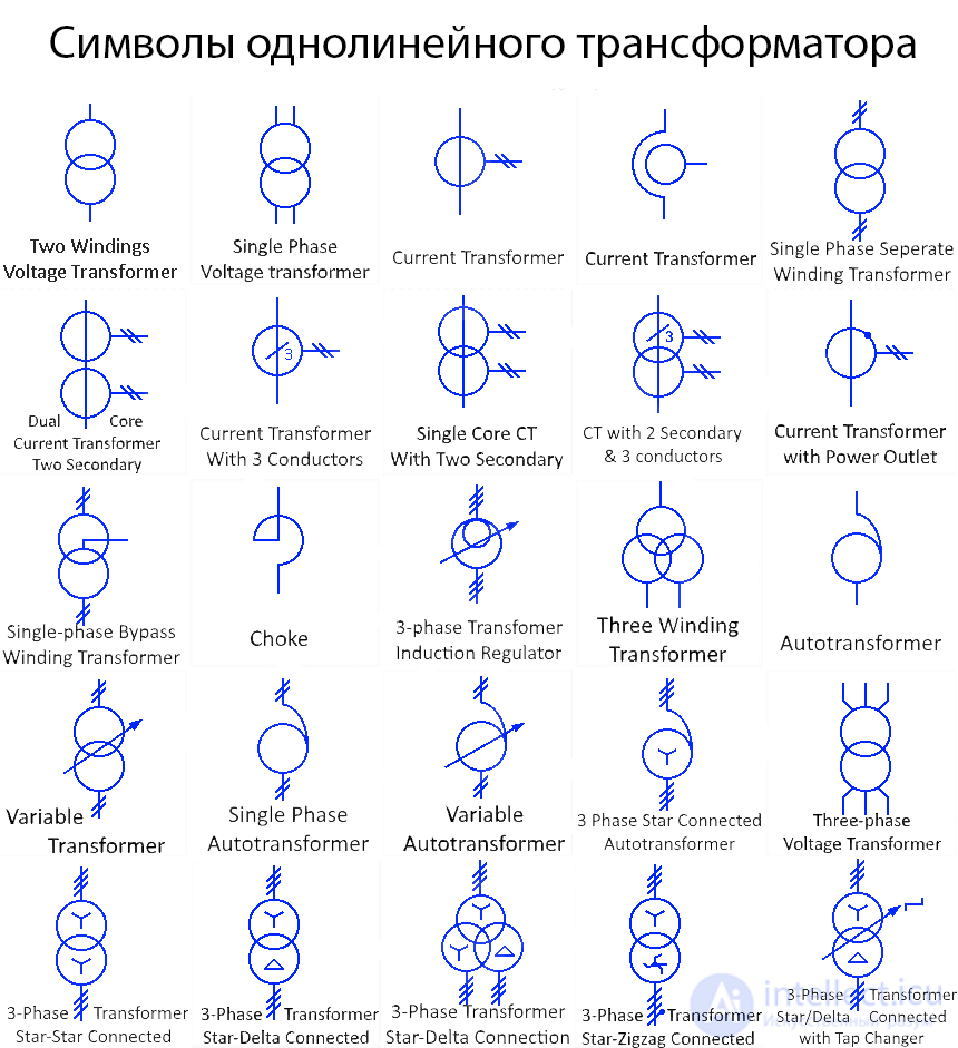
Two-winding transformer
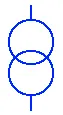
This is the general symbol for a two-winding transformer, single-line representation. Two-winding transformers consist of two windings connected together through an alternating magnetic flux.
Single-phase two-winding transformer
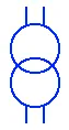
This is the SLD (single-line diagram) of a single-phase two-winding transformer. Such a transformer has two windings, i.e., a primary and a secondary, both used by a single phase. It has two primary terminals and two secondary terminals.
Air-core transformer
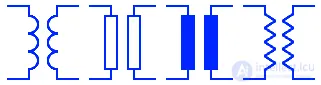
These symbols represent an air-core transformer. An air-core transformer has no magnetic core; instead, the winding is wound around plastic (a non-magnetic material), or there is no core at all. A magnetic core has core losses that increase with frequency, so an air-core transformer is used for radio-frequency applications.
Saturable reactor transformer

This is a type of transformer whose core can be intentionally saturated. Core saturation is the point at which the core becomes fully magnetized and produces maximum flux. Core saturation is controlled by a DC control winding. During saturation, the reactance decreases, which causes the current to increase.
Iron-core transformer

The core of this transformer is made of iron. Iron has high magnetic permeability, which allows it to carry a high magnetic flux, thereby increasing the induction between the windings. The drawback of an iron core is eddy-current losses (core losses), which depend on the supply frequency. Therefore, they are used for low-frequency applications.
Ferrite-core transformer

This symbol represents a transformer consisting of a ferrite core. Ferrite is a magnetic material with very high magnetic permeability, which increases the flux inside the transformer core. Ferrite also has very low electrical conductivity, which reduces the eddy-current losses that arise inside the core.
Variable transformer
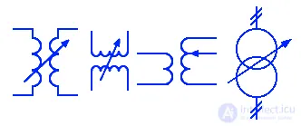
A variable transformer is a type of transformer that can provide a variable secondary voltage from the same primary voltage. It can change the output voltage by changing the number of turns, by using different tap points, or by changing the coupling. The Variac is the most common variable autotransformer.
Single-phase transformer with separate windings
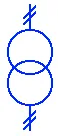
This is the SLD representation of a single-phase transformer with a separate winding for the primary and secondary terminals. The double dashed line represents two terminals for each winding.
Shielded transformer

A shielded transformer has an electrostatic shield between the primary and secondary windings, which prevents the transmission of large voltage spikes and high-frequency noise. The shield is grounded, and the capacitance between the shield and the primary winding prevents the transmission of noise due to high frequency.
Current-regulating transformer

This type of transformer provides a constant current even if the voltage increases or decreases. A transformer with a memory core regulates current by saturating the core using a DC control winding.
Voltage-regulating transformer

Voltage regulation of a transformer means maintaining a constant secondary voltage across the load range. This type of transformer regulates its voltage, i.e., it provides a constant voltage as the load current increases or decreases.
Moving-magnet transformer

As the name suggests, the voltage in this transformer coil is induced by the movement of a magnet in close proximity to the coil. A phono preamp uses an MM transformer and converts the movement of the stylus into an electrical signal by moving a magnet attached to its tip.
Adjustable-core transformer
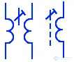
This type of transformer has an adjustable core that increases or decreases the flux linkage between the windings to increase or decrease the current. This type of transformer is used to control current in welding applications.
Current transformer
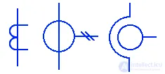
A current transformer is a type of instrument transformer used to step down a high alternating current in a line to safe levels for measurement purposes. The current produced in the secondary winding is proportional to the current in the primary winding (conductor) and is measured by connecting an ordinary ammeter to it.
Dual-core current transformer
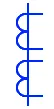
This type of current transformer has two cores. A single conductor (primary) passes through both cores of the transformer. The dual core of the transformer increases the transformer's power rating.
Dual-core current transformer with two secondary lines
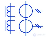
This is a dual-core current transformer that has two cores, each with an individual secondary winding. Each winding has a different turns ratio, which provides access to two different rated currents on each individual winding.
Current transformer with 3 conductors
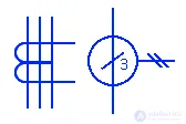
This type of CT is also known as a CBCT (Core Balance Current Transformer). It has 3 primary conductors (3 phases) passing through its core. The total vector sum of the current under normal conditions is zero. When a ground-fault current occurs, a difference appears across the CBCT, which is connected to an alarm system.
Single-core current transformer with two secondary and three primary conductors
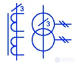
This symbol represents a current transformer with 2 secondary windings on a single core. 3 primary conductors pass through its core. The separate secondary winding provides a different rated current and turns ratio.
Single-core current transformer with two secondary windings
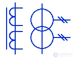
This type of current transformer has two secondary windings on a single core. Each winding provides a different turns ratio, offering different rated currents.
Choke
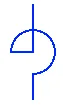
A choke consists of two separate windings wound on a single core in opposite directions. It is used to block high-frequency current while allowing direct current and low-frequency alternating current to pass.
Step-down transformer

A step-down transformer is a type of transformer that converts a high primary voltage into a low secondary voltage. It also converts a low primary current into a high secondary current. A step-down transformer has fewer turns in the secondary winding than in the primary. The conversion depends on the transformer's turns ratio.
Step-up transformer
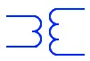
A step-up transformer converts a low primary voltage into a high secondary voltage. It also converts a high primary current into a low secondary current. It is mainly used in transmission lines to reduce the losses that occur in the transmission line, as well as to meet the voltage requirements of the circuit. It has a small number of primary turns and then secondary turns.
Center-tapped transformer

A center-tapped transformer has a tap point at the center of the secondary winding, which allows us to access half the number of turns in the secondary winding. The voltage between the center tap point and either end of the winding is half the voltage of the full winding.
Transformer with winding polarity

The polarity of a winding in a transformer is indicated by a dot. If current enters the primary dotted terminal, then the voltage induced at the secondary dotted terminal will be positive. If current exits the primary dotted terminal, then the voltage induced at the secondary dotted terminal will be negative. These are mainly used for connecting transformers in parallel in order to increase their power capacity.
Three-winding transformer
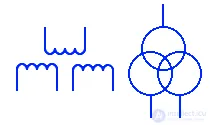
In addition to the primary and secondary windings, there is another winding called the tertiary winding, hence it is known as a three-winding transformer. Do not confuse it with a three-phase transformer, since a three-phase transformer has only 2 windings, i.e., primary and secondary. The tertiary winding is used to provide reactive power where needed, or to supply an auxiliary load with different voltage and power levels.
Autotransformer
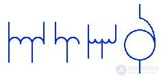
This type of transformer has only one coil. The turns of the coil are divided in a fixed proportion, which acts as the primary and secondary simultaneously. There is no electrical isolation between the coil and the secondary voltage, which results from self-induction as well as electrical conductivity. Small size, low cost, and high efficiency are the main advantages of an autotransformer.
Single-phase autotransformer
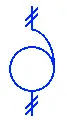
This SLD symbol represents a single-phase autotransformer. It has only one winding, which is used by the same phase conductor. There are two input terminals as well as two output terminals, taken from the same coil. They are used for single-phase applications.
Variable autotransformer
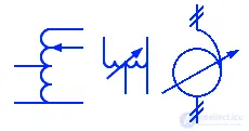
A variable autotransformer, also known as a Variac, has a sliding brush that continuously moves along the winding, increasing or decreasing the transformer's turns ratio. The voltage in the secondary winding changes due to the changing turns ratio.
Iron-core autotransformer

This symbol represents an autotransformer whose winding is wound around an iron core. The iron core increases the magnetic flux, which increases the self-induction between the turns.
Three-phase potential transformer
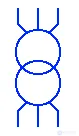
This symbol represents a three-phase potential transformer. It consists of 6 windings wound around a single core. There are 3 windings on each side, i.e., the primary and secondary sides. However, the windings can be connected in either of two most common configurations: star or delta.
Three-phase star-star transformer
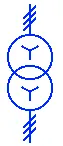
The primary windings and secondary windings of this 3-phase transformer are connected together in a star-star configuration. The star configuration represents a 4-wire, 3-phase system in which there is a neutral terminal.
3-phase transformer – induction regulator
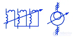
An induction regulator is an AC electrical machine similar to an induction motor, used to provide a constant AC voltage. The primary and secondary windings are connected in series. Its output voltage depends on the turns ratio, and it can provide a constant voltage ranging from 0 to the maximum output voltage.
3 single-phase transformers in a star/star configuration
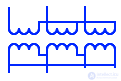
This is the symbol used for 3 single-phase transformers whose primary and secondary windings are connected in a star configuration. The star configuration is obtained by joining one end of all three windings together to create a neutral point.
Three-phase star-connected autotransformer
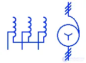
This symbol represents a star-configured, three-phase autotransformer. A three-phase autotransformer has a total of three windings, which act as both the primary and secondary winding. There may be several tap points for a variable secondary voltage.
3-phase star-delta transformer
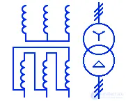
Also known as a 3-phase star-delta transformer (or star/delta), this is a 3-phase transformer whose primary winding is connected together in a star configuration and whose secondary winding is connected in a delta configuration. It converts a three-phase 3-wire system into a three-phase 4-wire system.
3-phase delta-star transformer
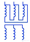
Also known as a delta-star transformer, the primary winding of this transformer is connected in a delta configuration, and the secondary winding is connected in a star configuration. It converts a 4-wire (three-phase) system into a 3-wire (three-phase) system.
3-phase star-delta transformer with tap changer
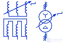
This symbol represents a 3-phase transformer connected in a star-delta configuration with a tap changer. The tap changer is used to regulate the output voltage by changing the transformer's turns ratio. The tap changer switches between multiple tap points, providing variable turns ratios.
3-phase star/star transformer with tap points
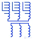
This is a 3-phase star-star connected transformer with several tap points for variable voltage. Each tap point provides a fixed output voltage depending on the turns ratio relative to the primary winding.
3-phase transformer with zigzag connection
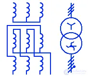
The primary winding of this type of 3-phase transformer is connected in a star configuration, while the secondary winding is connected in a zigzag, or "interconnected star," configuration. Each phase of the zigzag transformer has two halves. The zigzag configuration provides a neutral for grounding or for supplying a single-phase load.

Comments